Deploy Secure Mesh Site v2 in Nutanix (ClickOps)
Objective
This guide provides instructions on how to create a Customer Edge (CE) Site using the F5® Distributed Cloud Console for Nutanix.
Important: This guide does not provide instructions on how to deploy an F5® App Stack Site.
Planning
Read the following documents before deploying a Secure Mesh Site in any provider environment:
- Understanding F5 Distributed Cloud - Customer Edge (CE)
- CE Datasheet
- CE Supported Platforms Guide
- Customer Edge Site Sizing Reference
- CE Performance Guide: Contact your account representative on CE performance-related information.
- Proxy for CE Registration and Upgrades Reference
- Secure Mesh Sites v2 Frequently Asked Questions
- Customer Edge Registration and Upgrade Reference
- F5 Customer Edge IP Address and Domain Reference for Firewall or Proxy Settings
General Prerequisites
The following general prerequisites apply:
-
A Distributed Cloud Services Account. If you do not have an account, see Getting Started with Console.
-
Nutanix 6.8.1 or later. The examples in this guide are based on version 6.8.1.
-
At least one interface in your Nutanix environment with Internet connectivity.
-
Resources required per node: Minimum 8 vCPUs, 32 GB RAM, and 80 GB disk storage. For a full listing of the resources required, see the Customer Edge Site Sizing Reference guide. All the nodes in a given CE Site should have the same resources regarding the compute, memory, and disk storage. When deploying in cloud environments, these nodes should use the same instance flavor.
-
Customer Edge (CE) deployments require connectivity to F5 Distributed Cloud. See the F5 Customer Edge IP Address and Domain Reference for Firewall or Proxy Settings guide for the list of IP addresses and domain names that need to be allowed.
-
The new Secure Mesh Site workflow enables you to have up to eight interfaces. However, these interfaces should be in different subnets. Therefore, make sure you have the required subnets available before creating the CE Site nodes.
-
If deploying the CE site with High Availability (HA) enabled, Internet Control Message Protocol (ICMP) must be opened between the CE nodes on the Site Local Outside (SLO) interfaces. This is needed to ensure intra-cluster communication checks.
Important: After you deploy the CE Site, the IP address for the SLO interface cannot be changed. Also, the MAC address cannot be changed.
Note that this document describes one- and two-interface deployments for CE sites with HA-disabled (single-node) and HA-enabled (three-node cluster).
Configuration Overview
To create a Secure Mesh Site with Nutanix, here are the high-level steps:
- Site object configuration: Create and configure a Secure Mesh Site object using F5 Distributed Cloud Console.
- Image management: Download the software image (qcow2) from the F5 Distributed Cloud Console.
- Node management: Use the downloaded image (qcow2) to launch CE nodes. Each node is a virtual machine (VM).
- Network interface management: Add additional interfaces on the nodes, if necessary.
Important: The first interface of a CE node must be mapped to the Site Local Outside (SLO) VRF, which should allow connectivity to F5 Distributed Cloud.
Procedure
In this guide, the procedure demonstrates the steps to deploy a single-node site with dual interfaces (ingress/egress). However, this guide also explains the necessary deviations from this specific model where necessary, making it flexible to adjust to different node and interface requirements.
Create Site Object
Step 1: Enter metadata information for site.
-
In Distributed Cloud Console, select Multi-Cloud Network Connect.
-
Navigate to Manage > Site Management > Secure Mesh Sites v2.
-
Select Add Secure Mesh Site to open the configuration form.
-
In the Metadata section, enter a name for the site.
-
Optionally, select labels and add a description.
Step 2: Select the provider name as Nutanix.
-
Set the Provider Name option to Nutanix.
-
For High Availability, choose an option. If it is Disabled, then the CE Site only supports one node. If it is Enabled, the CE Site requires three nodes. Additional nodes can only be added to CE sites when HA is Enabled.
Important: The High Availability mode cannot be changed after the CE Site is created.
- Leave the other options with their default values. These options have intelligent default values and do not need further configuration. Refer to the Create Secure Mesh Site guide for more information on these options.
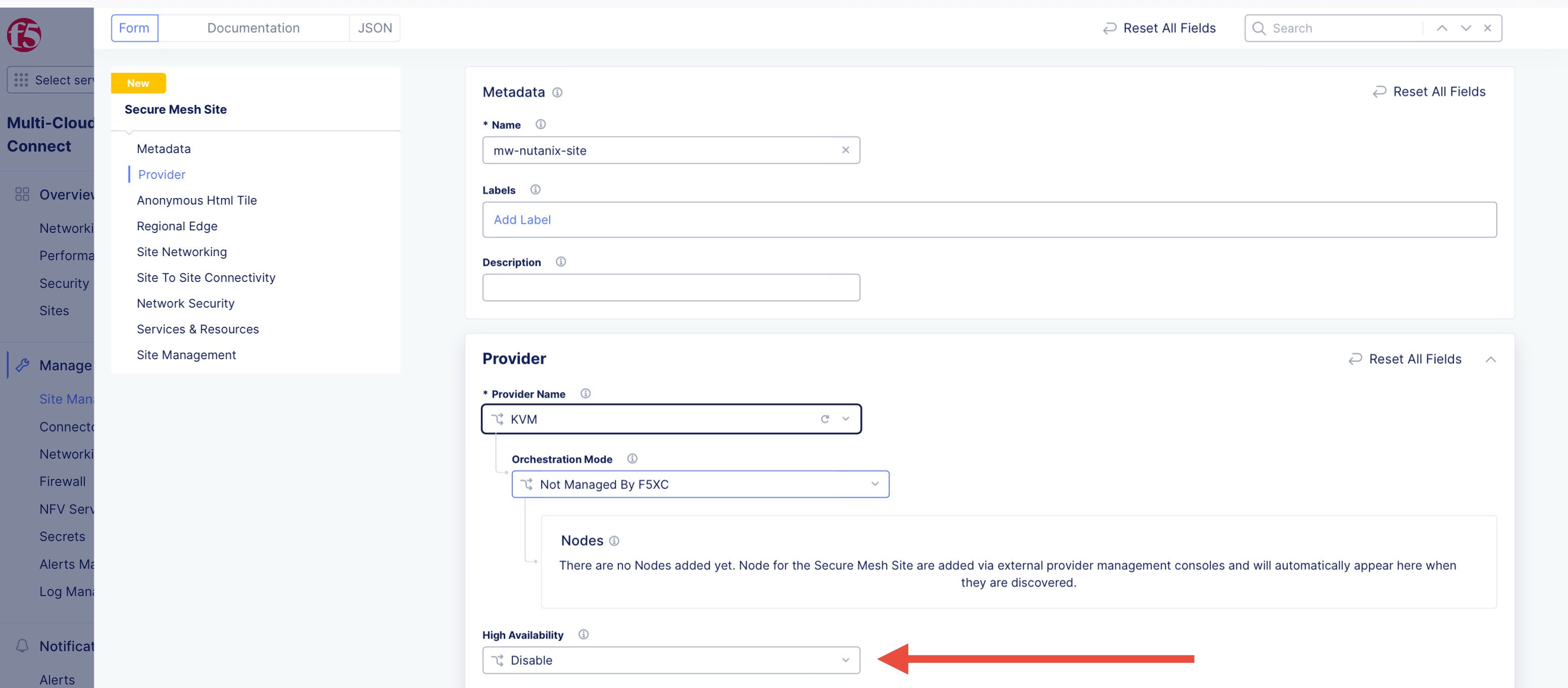
Figure: Provider Type
- Click Add Secure Mesh Site.
Download Node Image
Nutanix uses the qcow2 file format as the image format for bringing up virtual machines. You can download this qcow2 file using the following steps:
-
Navigate to Manage > Site Management > Secure Mesh Sites v2.
-
From the Secure Mesh Sites page, for your Site, click ... > Download Image and then save the image locally.
-
Ensure that you validate the MD5SUM of the image for an integrity check.
-
Optionally, to obtain a download link that you can use with CLI utilities, such as curl or wget, click Copy Image Name.
Generate Node Token
A one-time node token is required to register a CE Site node to the Distributed Cloud Console. A new token must be generated for every new node in a CE Site. A token is valid for 24 hours. Make sure that the CE node is deployed soon after the token is generated.
The token is included in the cloud-init information under the Content variable. Also included are two variables commented out: slo_ip and slo_gateway. If you are using a static IP address and not DHCP, you must configure these variables and remove the hashtag, to provide an IP address for the VM (node).
-
In Distributed Cloud Console, select the Multi-Cloud Network Connect workspace.
-
Navigate to Manage > Site Management > Secure Mesh Sites v2.
-
For your site, click ... > Generate Node Token.
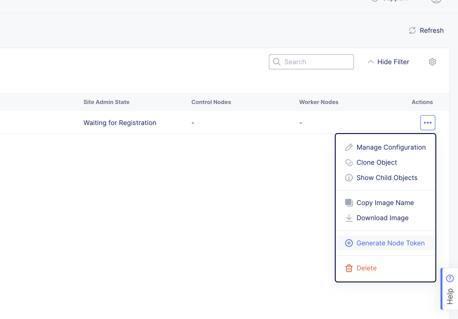
Figure: Node Token
-
Click Copy cloud-init.
-
Save the value locally. This token is used later. The token value is hidden for security purposes.
-
Click Close.
-
Generate one token per node you intend to deploy.
-
For static IP address configuration in the cloud-init information, configure the slo_ip and slo_gateway variables and remove the hashtags.
#cloud-configwrite_files: - path: /etc/vpm/user_data permissions: 644 owner: root content: | token: <secret-token-hidden> slo_ip: 10.0.0.5/24 slo_gateway: 10.0.0.1Create CE Image in Nutanix
Upload the downloaded qcow2 image into Nutanix PRISM to create the CE Site image.
Important: The name of the VM should not have "." in it. For example, the hostname can be node-0 or node0, but it cannot be node.f5.com since it is not supported. Your node VM name must adhere to DNS-1035 label requirements. This means the name must consist of lower case alphanumeric characters or “-“, start with an alphabetic character, and end with an alphanumeric character.
If configuring a multi-node site, each node hostname must be unique.
-
Log into Nutanix PRISM cloud platform.
-
Select Settings from the upper left menu, and then click Image Configuration on the left pane.
-
Click Upload Image and either copy and paste the qcow2 image URL or upload the previously downloaded image from your computer.
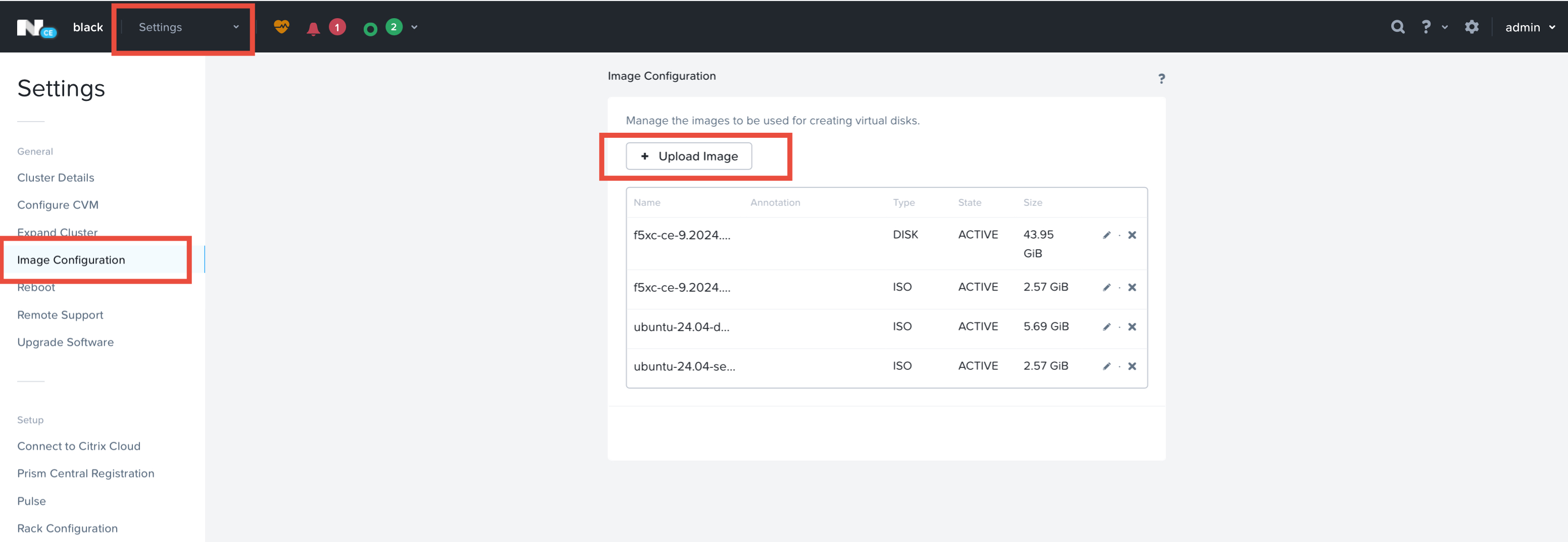
Figure: Nutanix PRISM Image Configuration
- Name the image. For example, use the base name of the URL without the .qcow2 suffix.
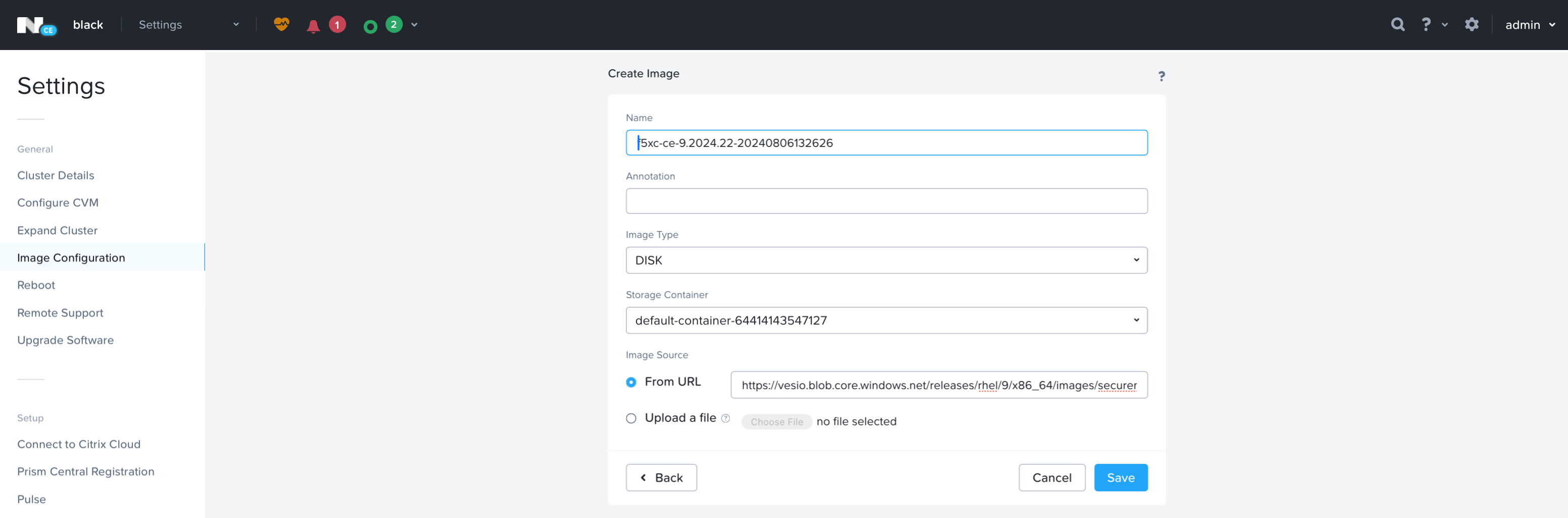
Figure: Nutanix PRISM Image Name
Bootstrap the Nutanix Node
- In the Nutanix PRISM web UI, select VM from the upper left bar, and then click Create VM on the upper right side to create a new VM.
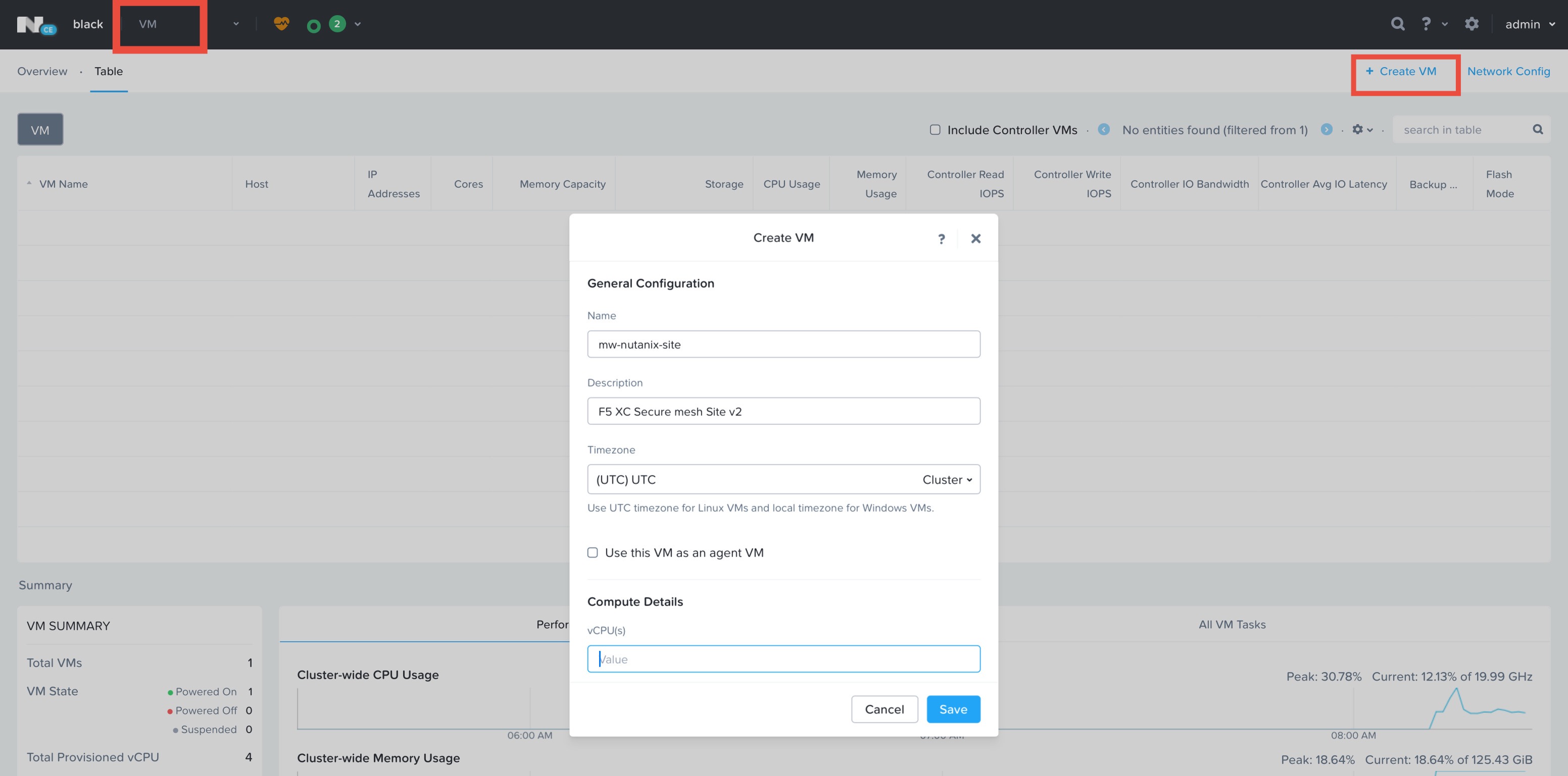
Figure: Nutanix PRISM VM Creation
-
Enter a name and optional description.
-
For compute resources, set at least 8 vCPUs and 32 GB of memory (RAM). Keep default Boot Configuration (legacy BIOS).
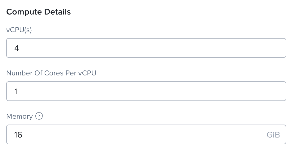
Figure: Nutanix PRISM VM Resources
-
Scroll down to edit the Disks section and remove CD-ROM and add new disk via Clone from Image Service.
-
Select the qcow2 image file by name from the Image Services created in the previous section.
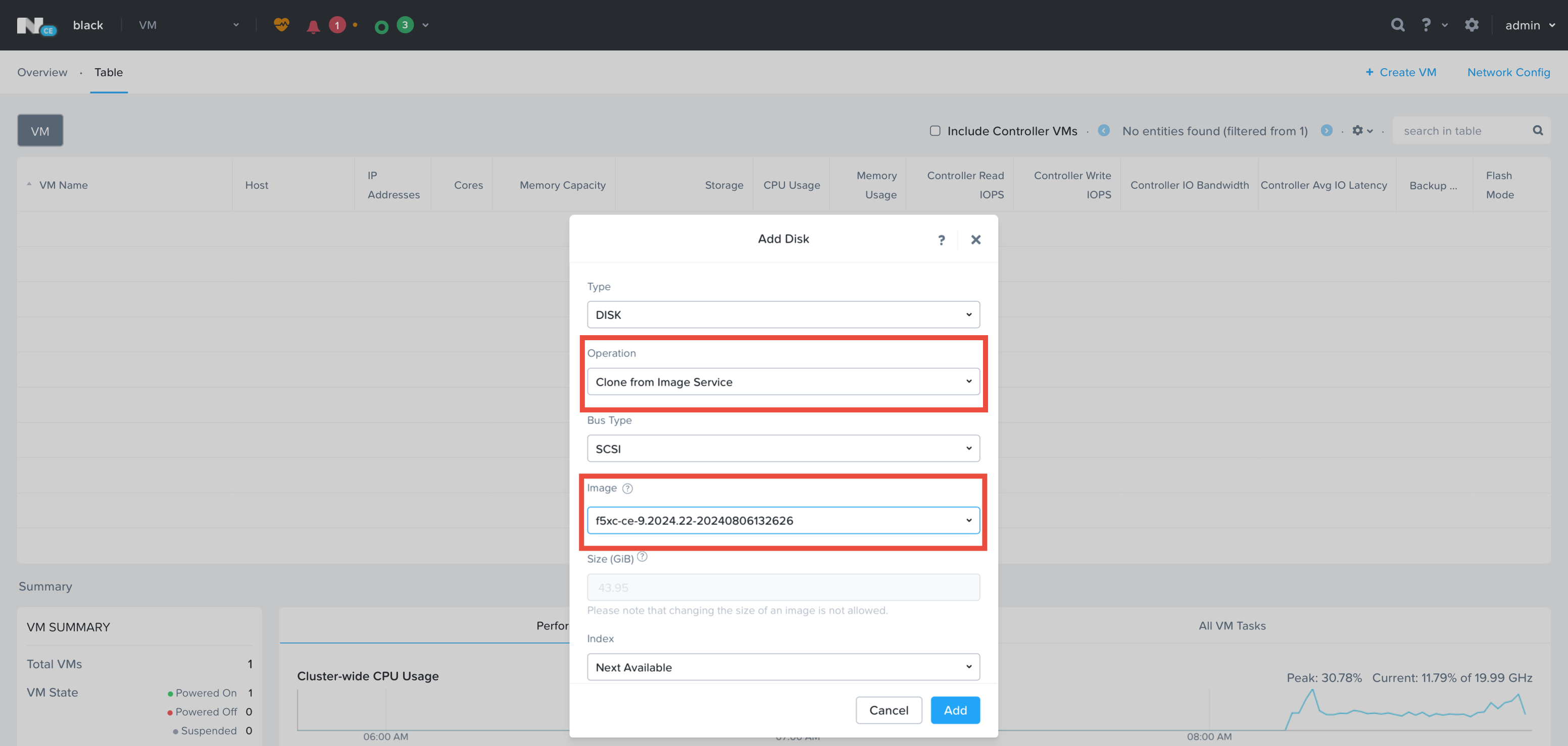
Figure: Nutanix PRISM VM Disk
- Add at least one network interface that is connected to an existing IPv4 subnet with Internet access.
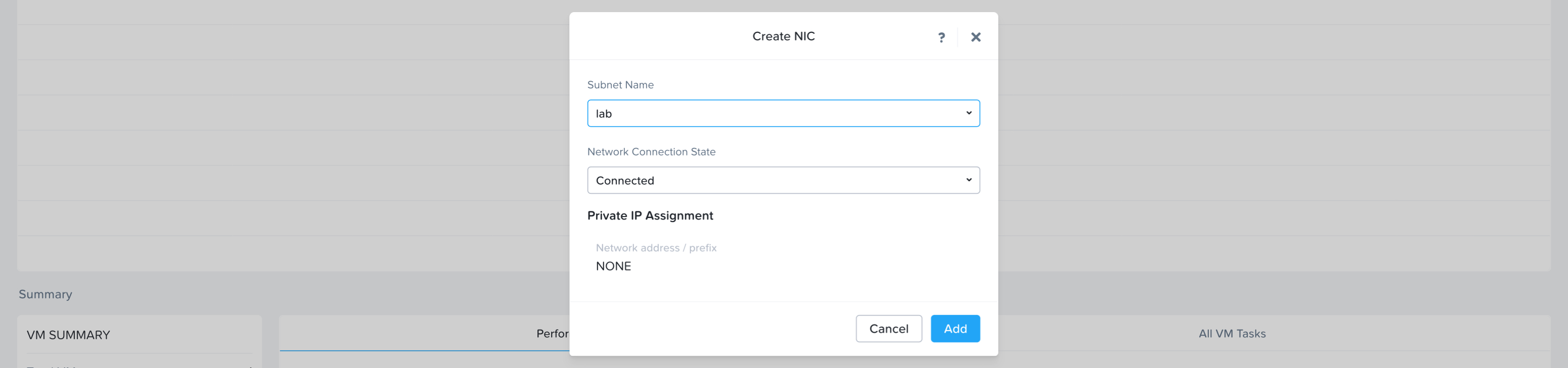
Figure: Nutanix PRISM VM Network Interface
-
Scroll further down and click Custom Script.
-
In the Type or Paste Script field, paste the cloud-init information (which includes the site token) copied from the Generate Node Token section.
-
Click Save.
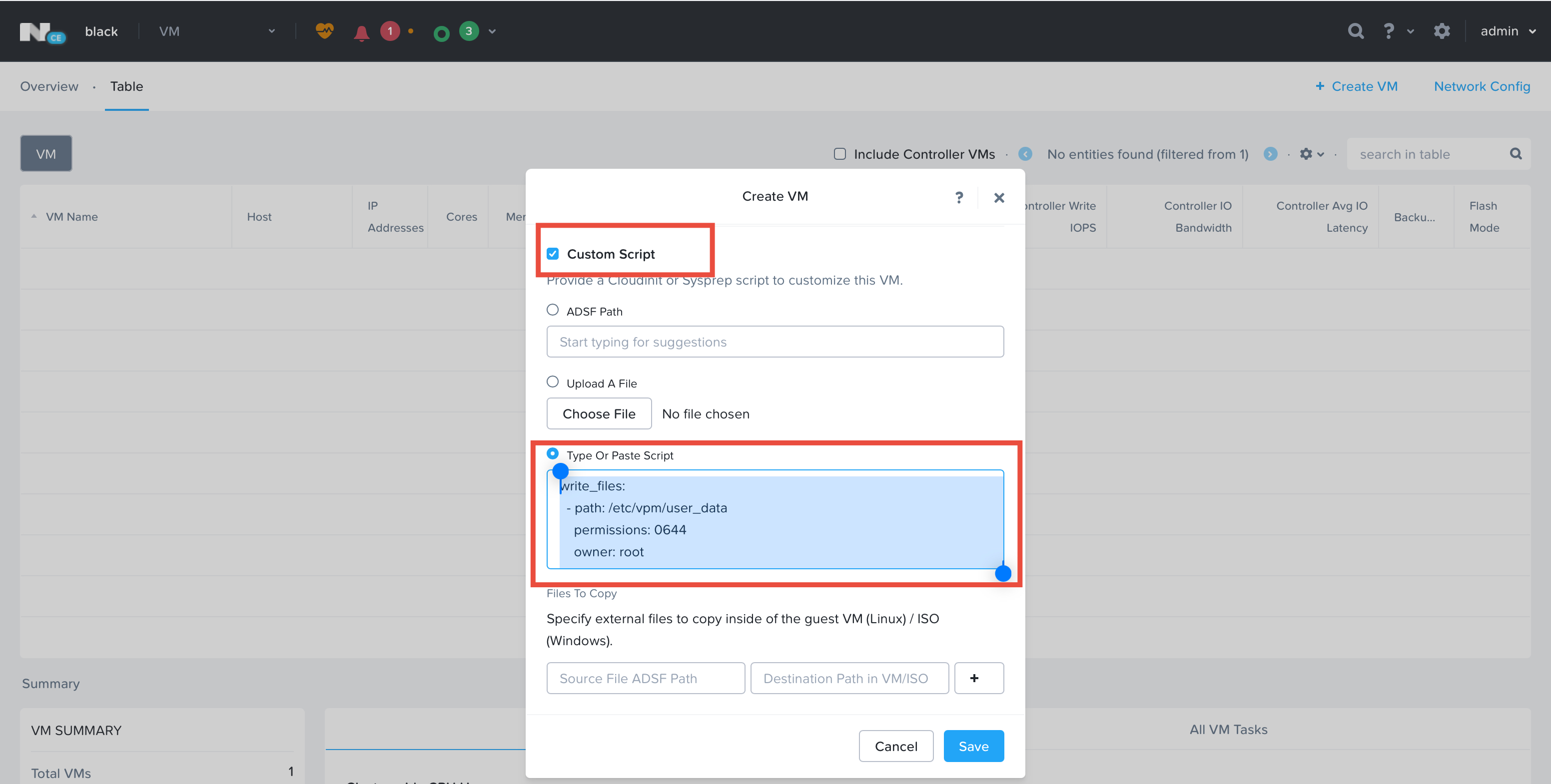
Figure: Nutanix PRISM VM Cloud Config
- Power on the VM.
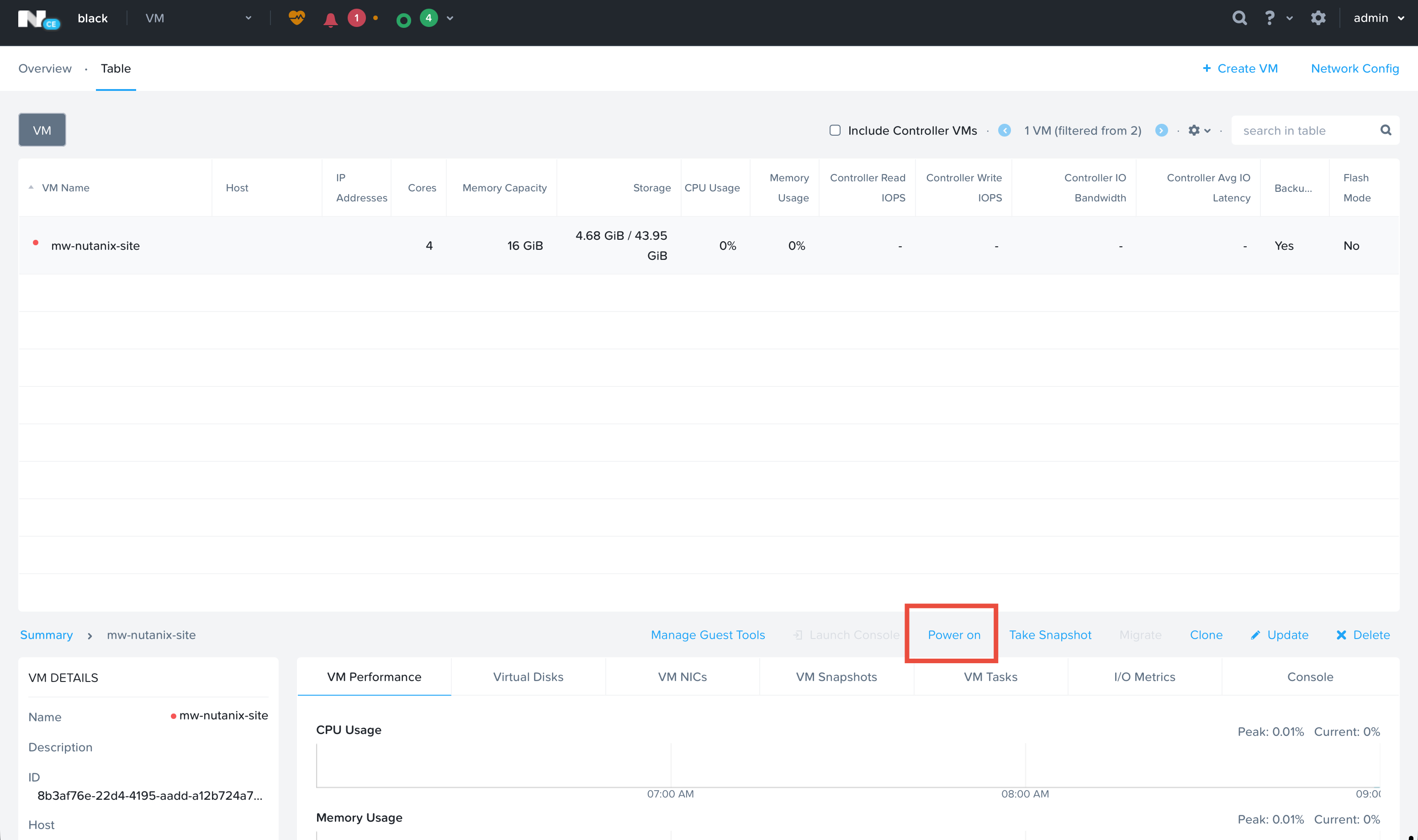
Figure: Nutanix PRISM VM Power On
Verify CE Site Registration
-
In Distributed Cloud Console, navigate to Multi-Cloud Network Connect > Overview > Infrastructure > Sites.
-
Select the site. The Dashboard tab should clearly show that the CE Site has registered successfully with the System Health of 100% as well as Data Plane/Control Plane both being up.
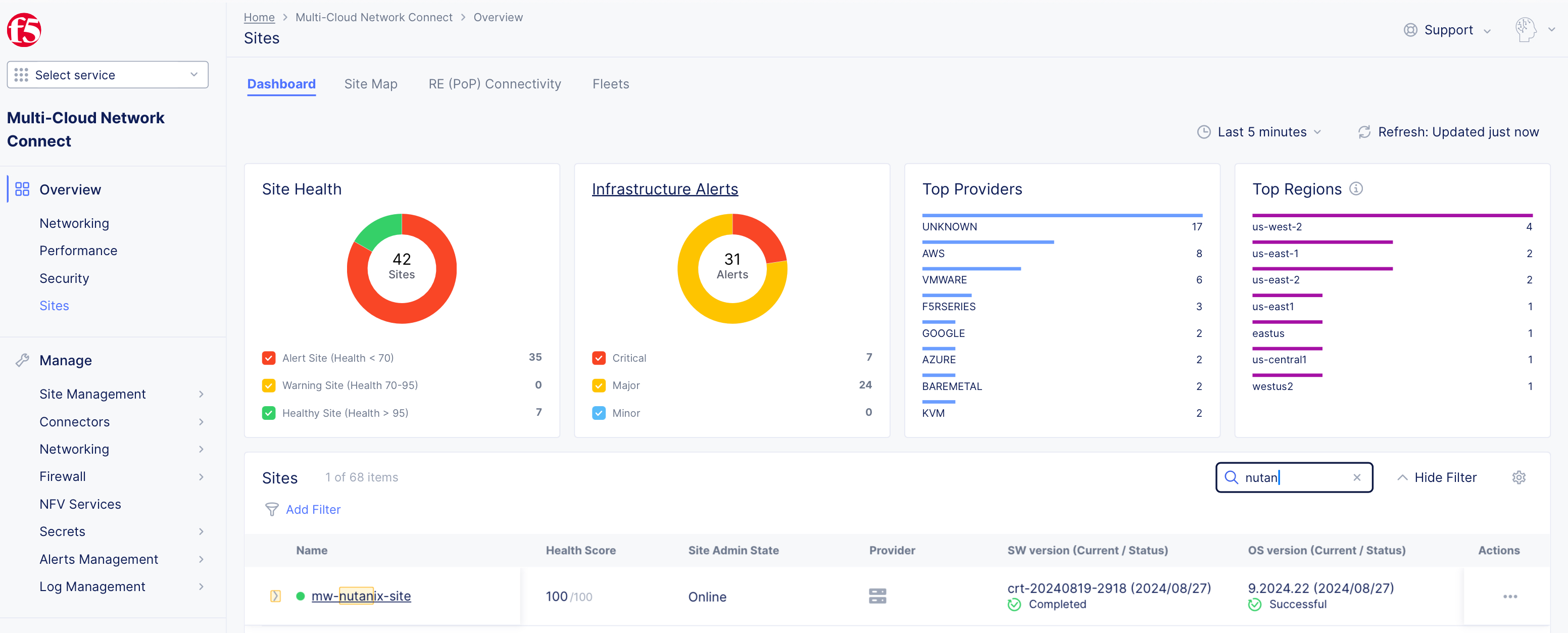
Figure: Confirm Site Health
- Click the Infrastructure tab to see the Nodes and Interfaces with their IP addresses.
Note: For more information on the site registration process, see the Customer Edge Registration and Upgrade Reference guide.
Manage Network Interfaces (Optional)
After your CE Site registers successfully, you might want to add additional network interfaces to meet your requirements. Ensure that you connect another network interface to the node VM.
Important: Adding or removing network interfaces causes the data plane services on the CE node to restart. Therefore, F5 strongly recommends that you perform this operation during maintenance windows. As data plane services restart, traffic drops are expected, as well as tunnels to F5 Distributed Cloud REs going down.
All CE nodes in a given CE Site should have the same number of network interfaces attached. CE nodes with non-homogenous interfaces within a CE Site might cause issues.
Each node in the CE Site should have interfaces with the same VRFs assigned. For example: If a CE Site has three nodes, with each node having two interfaces - the first interface on each node is auto-configured to be in the SLO VRF (to connect to F5 Distributed Cloud). If the second interface on node-1 is in the SLI VRF, then the second interface on node-2 and node-3 must also be in the SLI VRF.
When new interfaces are added, they are auto-discovered. You can configure the interface (for example: place the interface in the appropriate VRF) from the CE Site configuration.
The first interface of the CE nodes should not be removed or modified.
After you configure the SLO interface with a static IP address, DHCP will still be displayed in the Console. However, your static IP configuration is well taken into account. Also, remember that you cannot modify SLO parameters once the node is registered and deployed.
Add New Interface
-
Power down all CE nodes (VMs) of the CE Site prior to adding any new interfaces or modifying any existing interfaces.
-
Attach additional network interface(s) to the CE nodes. Make sure to maintain homogeneity. As in, add the same number of interfaces mapped to the same port groups on all CE nodes (VMs).
-
Power on the CE nodes (VMs). The CE Site resource in F5 Distributed Cloud auto-detects changes in the interfaces.
-
In the Multi-Cloud Network Connect workspace, click Manage > Site Management > Secure Mesh Sites v2.
-
For your Site, click ... > Manage Configuration.
-
Click Edit Configuration.
-
In the Provider section, click the pencil button to edit the desired node.
-
Click the pencil button next to the newly discovered interface. The MAC address is shown in the table for convenience.
Note: Interface Name is not a mandatory field but is recommended to be configured.
-
Select the un-configured network device that is detected by the node by clicking See Suggestions.
-
From the IPv4 Interface Address Method menu, select the IP address configuration from the following options:
- DHCP Client Static IP
Important: The IP address for the SLO interface cannot be changed. This change can damage the cluster configuration.
-
Assign interface configurations for the Select VRF option to VRF. The default and most common option is Site Local Inside (Local VRF), but can also be assigned to Segment (Global VRF).
-
Click Apply. Then, click Apply again.
-
Click Save Secure Mesh Site to complete the Secure Mesh Site configuration.
-
To view the interface details, navigate to the Infrastructure tab in the CE Site dashboard.
Day 2 Operations
- To monitor your Site, see the Monitor Site guide.
- To manage your Site software and OS updates, see the Manage Site guide.
- For troubleshooting issues, see the Troubleshooting Guide for Secure Mesh Site v2 Deployment guide. It provides step-by-step instructions to debug and resolve the issues that may arise due to registration and provisioning errors.
- For the latest on Distributed Cloud Services releases, see Changelogs.
- To view the various types of events generated, see the Events Reference guide.
Related Guides
To create a load balancer on the CE Site, see the HTTP Load Balancer or the TCP Load Balancer guides.