Deploy Secure Mesh Site v2 in OpenStack (ClickOps)
Objective
This guide provides instructions on how to create a Customer Edge (CE) Site using the F5® Distributed Cloud Console for OpenStack environment.
Important: This guide does not provide instructions on how to deploy an F5® App Stack Site.
Planning
Read the following documents before deploying a Secure Mesh Site in any provider environment:
- Understanding F5 Distributed Cloud - Customer Edge (CE)
- CE Datasheet
- CE Supported Platforms Guide
- Customer Edge Site Sizing Reference
- CE Performance Guide: Contact your account representative on CE performance-related information.
- Proxy for CE Registration and Upgrades Reference
- Secure Mesh Sites v2 Frequently Asked Questions
- Customer Edge Registration and Upgrade Reference
- F5 Customer Edge IP Address and Domain Reference for Firewall or Proxy Settings
General Prerequisites
The following general prerequisites apply:
-
A Distributed Cloud Services Account. If you do not have an account, see Getting Started with Console.
-
Resources required per node: Minimum 8 vCPUs, 32 GB RAM, and 80 GB disk storage. For a full listing of the resources required, see the Customer Edge Site Sizing Reference guide. All the nodes in a given CE Site should have the same resources regarding the compute, memory, and disk storage. When deploying in cloud environments, these nodes should use the same instance flavor.
-
Customer Edge (CE) deployments require connectivity to F5 Distributed Cloud. See the F5 Customer Edge IP Address and Domain Reference for Firewall or Proxy Settings guide for the list of IP addresses and domain names that need to be allowed.
-
F5 assumes that an existing IPv4 subnet exists with Internet connectivity to attach to the node.
-
The new Secure Mesh Site workflow enables you to have up to eight interfaces. However, these interfaces should be in different subnets. Therefore, make sure you have the required subnets available before creating the CE Site nodes.
-
If you are deploying the CE site with High Availability (HA) enabled, Internet Control Message Protocol (ICMP) must be opened between the CE nodes on the Site Local Outside (SLO) interfaces. This is needed to ensure intra-cluster communication checks.
Important: After you deploy the CE Site, the IP address for the SLO interface cannot be changed. Also, the MAC address cannot be changed.
Configuration Overview
To create a Secure Mesh Site with OpenStack, here are the high-level steps:
- Site object configuration: Create and configure a Secure Mesh Site object using F5 Distributed Cloud Console.
- Node creation prerequisites: Create objects that are associated with the CE nodes, including network security groups, networks, and more.
- Image management: Download the image locally and upload it to OpenStack environment.
- Node management: Use the uploaded image to launch CE nodes. Each node is a virtual machine (VM).
- Network interface management: Add additional interfaces on the nodes, if necessary.
Important: The first interface of a CE node must be mapped to the Site-Local Outside (SLO) VRF which should allow connectivity to the F5 Distributed Cloud.
The document describes one- and two-interface deployments for CE sites with HA disabled (single node) and HA enabled (three-node cluster).
Procedure
In this guide, the procedure demonstrates the steps to deploy a single-node site.
Create Site Object
-
Create a secure mesh site object in Distributed Cloud Console. Refer to the Create Secure Mesh Site guide.
-
Set the Provider Name option to OpenStack.
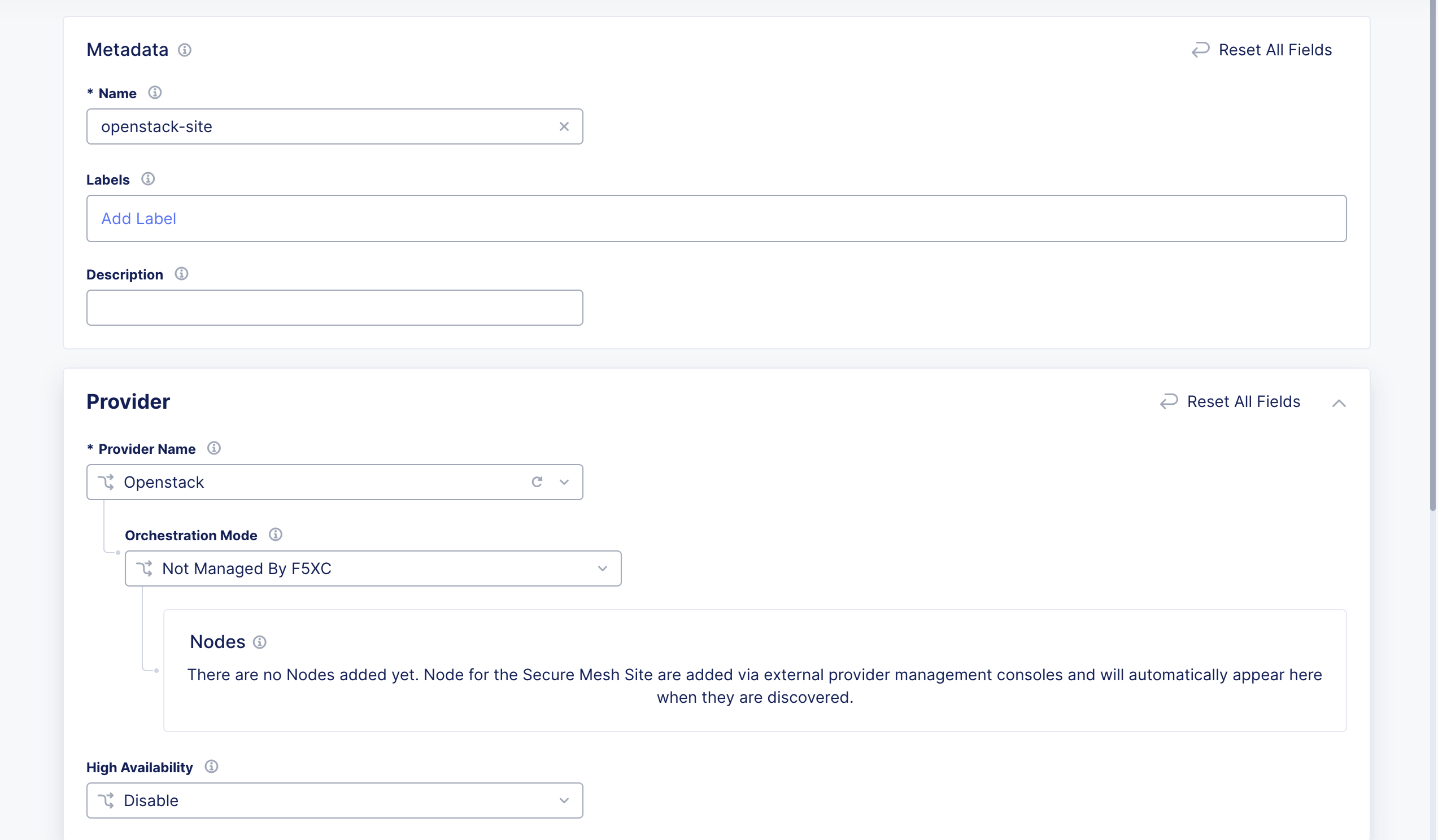
Figure: Provider Type
- For High Availability, choose an option. If it is Disabled, then the CE Site only supports one node. If it is Enabled, the CE Site requires three nodes. Additional nodes can only be added to CE sites when HA is Enabled.
Important: The High Availability mode cannot be changed after the CE Site is created.
-
Leave the other options with default values. These options have intelligent default values and do not need further configuration. Refer to the Create Secure Mesh Site guide for more information on these options.
-
Click Add Secure Mesh Site.
-
For your Site object, under Actions, click ... > Copy Image Name to receive a download link to use for CLI with the curl or wget commands. To download the image file locally, click Download Image.
Create a Network Security Group
Add rules for the following:
- Allow SSH from the instance.
- Allow ICMP for troubleshooting.
- Allow TCP for any port for the local UI on the CE.
- For three-node clusters, ensure that traffic is allowed between the nodes.
Download and Create Node Image
Step 1: Download and unzip file.
-
In Console, navigate to the Multi-Cloud Network Connect workspace.
-
Click Manage > Site Management > Secure Mesh Sites v2.
-
For your site, click ... > Download Image. This action starts downloading the
f5xc-ce-<version>.qcow2file onto your local machine.
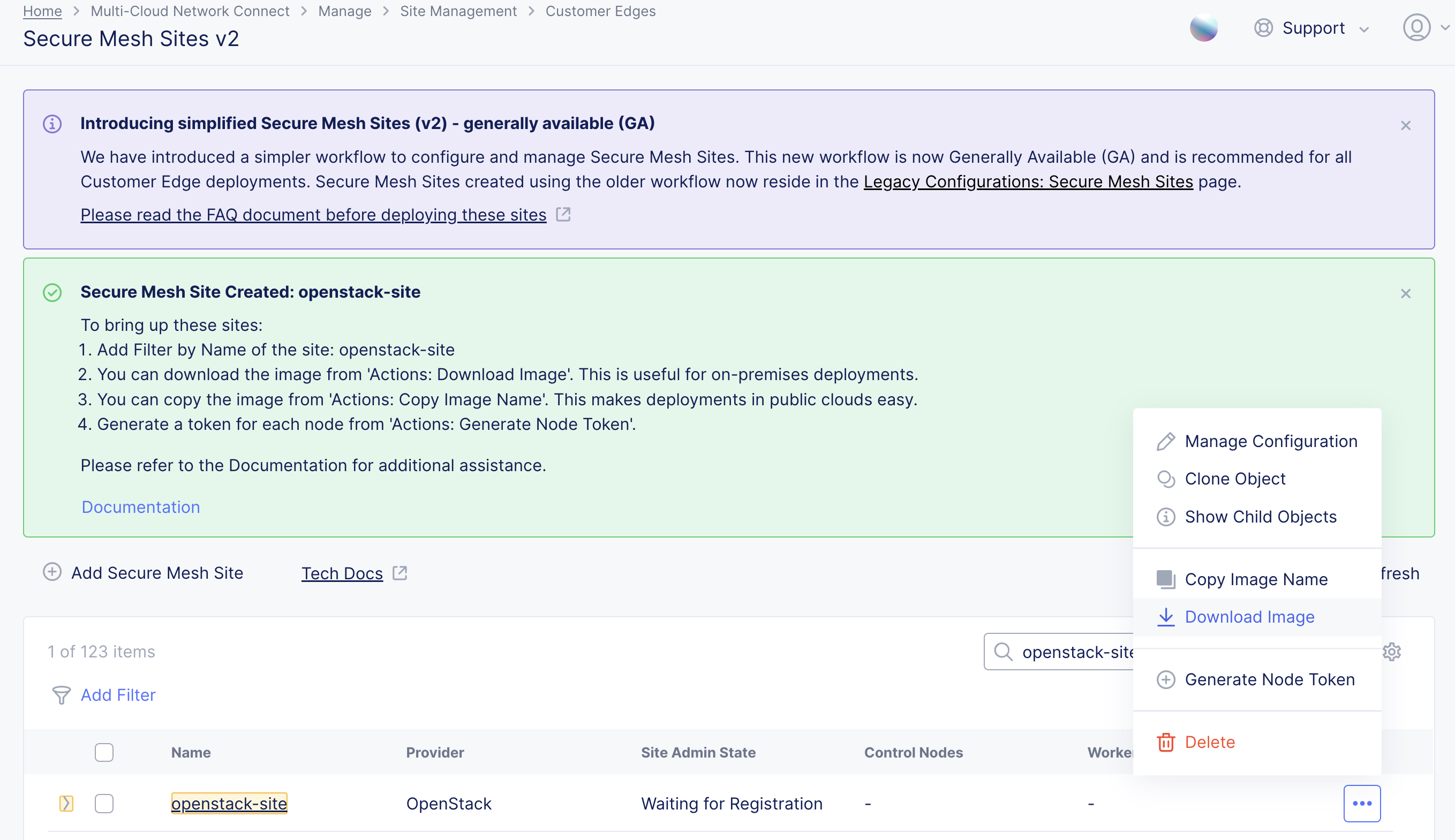
Figure: Download Node Image
Step 2: Upload file to OpenStack portal.
-
In OpenStack portal, navigate to the Images page under the Compute section.
-
Click Create Image.
-
Define the image name and then upload the image in the Image Source with format QCOW2. Leave all other default settings.
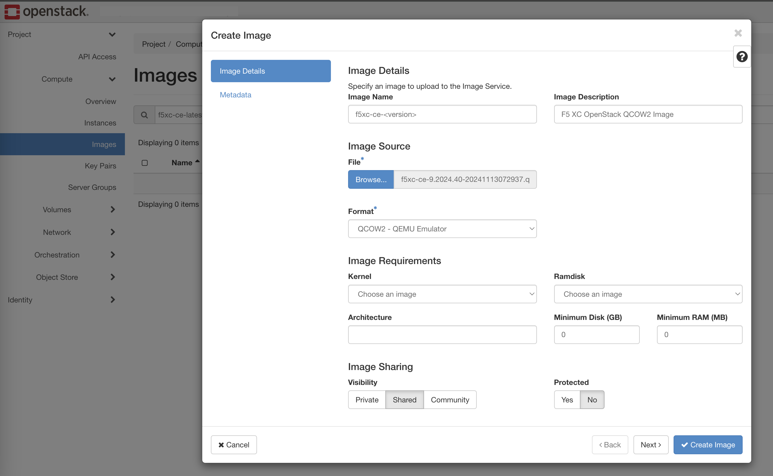
Figure: Upload Node Image
Configure Network Settings
Step 1: Create a new network.
Ignore this step if you already have such network configured in your OpenStack environment.
-
In OpenStack portal, navigate to Networks and click Create Network.
-
Configure the network details, such as network name, enable admin state, create subnet, and MTU. This network is used as the primary network for the site. Make sure this network is pingable and accessible from your local network. Also, this network should have connectivity to the public Internet.
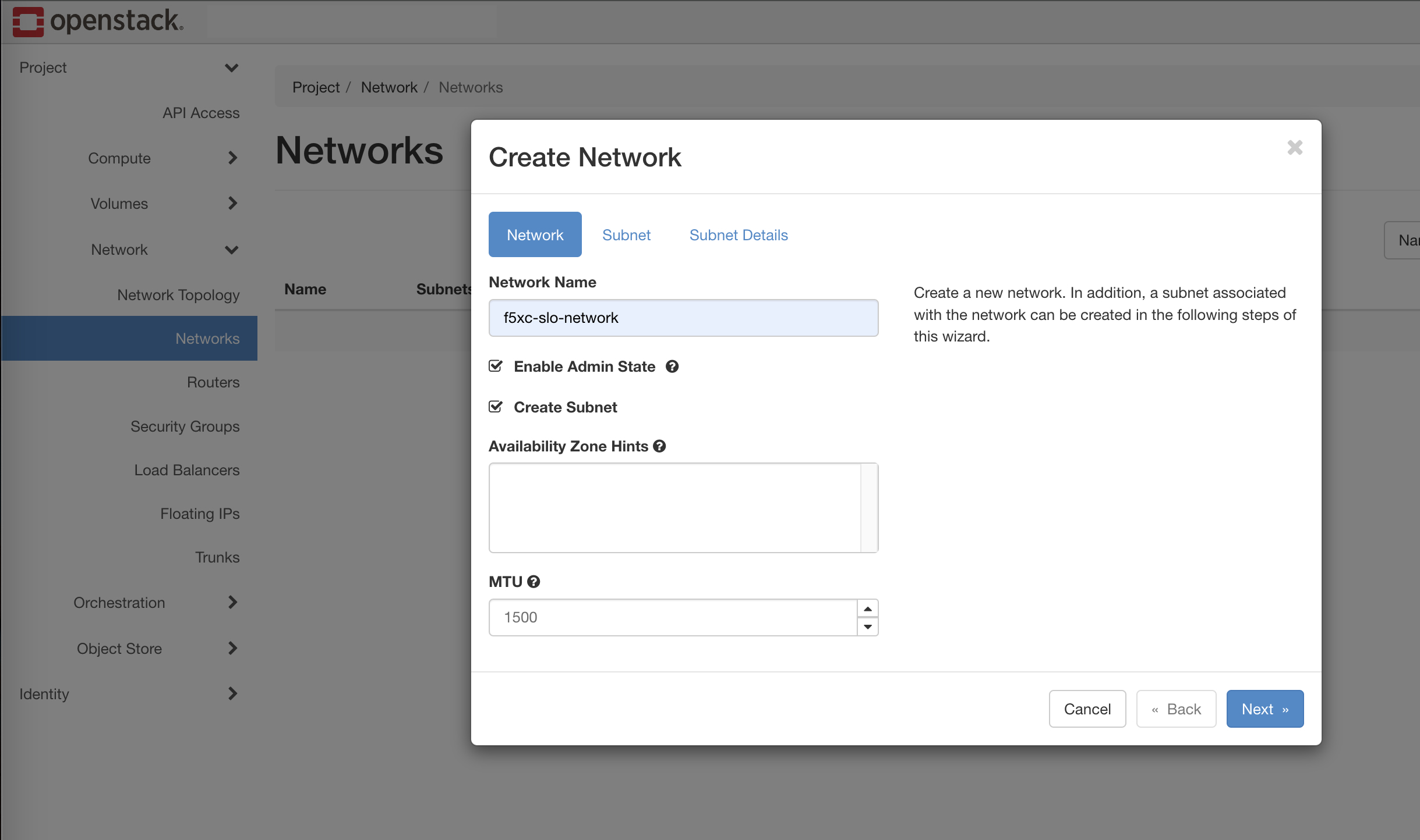
Figure: Create Network
Step 2: Add one or more subnets.
Ignore this step if you already have a subnet associated with this network.
-
Navigate to the Subnet tab and enter a Subnet Name and Network Address.
-
Set the IP Version to IPv4.
-
Enter a Gateway IP address.
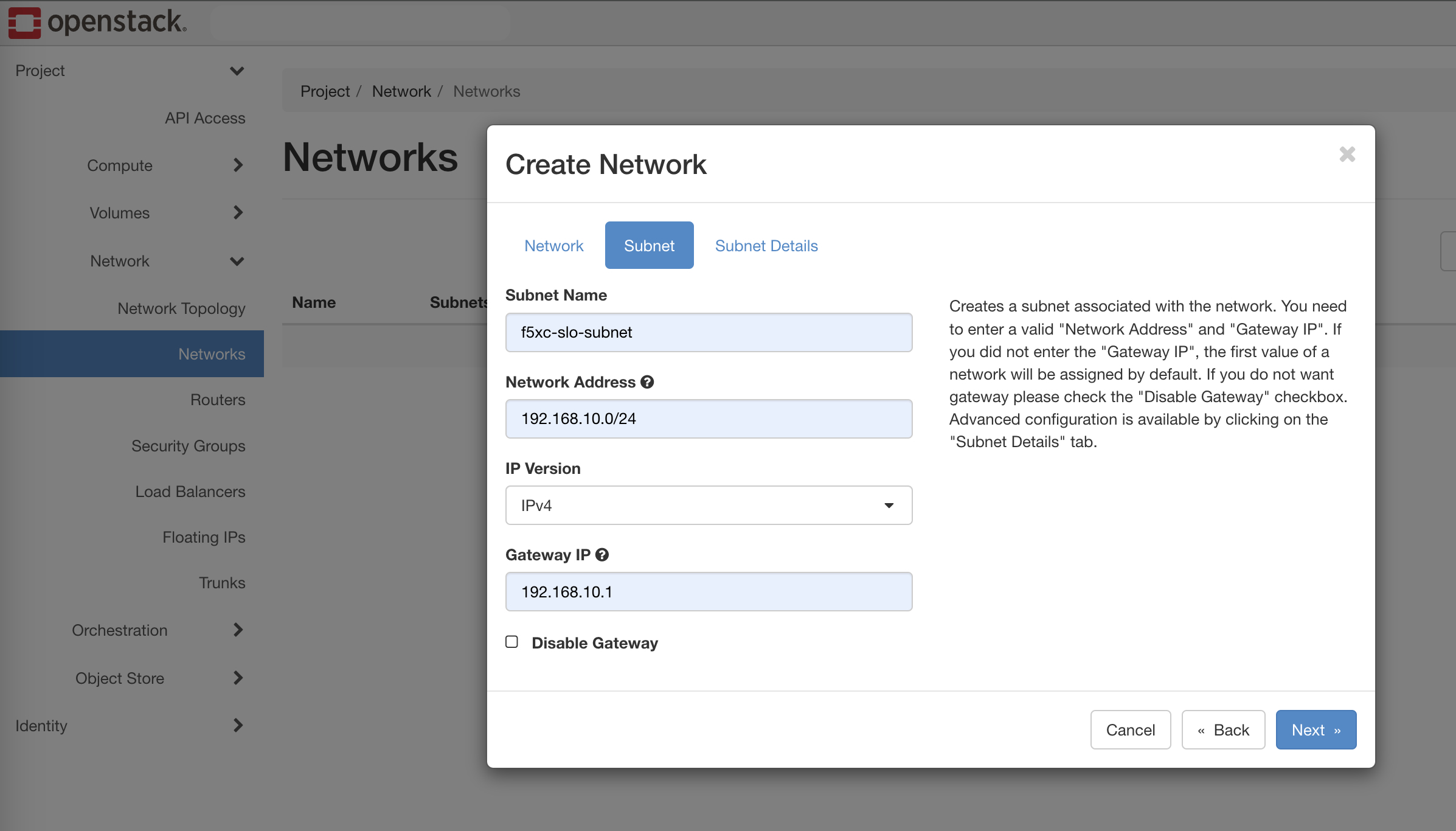
Figure: Add Subnet
Step 3: Configure advanced settings for subnet.
Ignore this step if you already have a pre-configured subnet.
-
In the Subnet Details tab, enter other details, such as Enable DHCP, Allocation Pools, DNS Name Servers and Host Routes (next hop), if any.
-
Click Create.
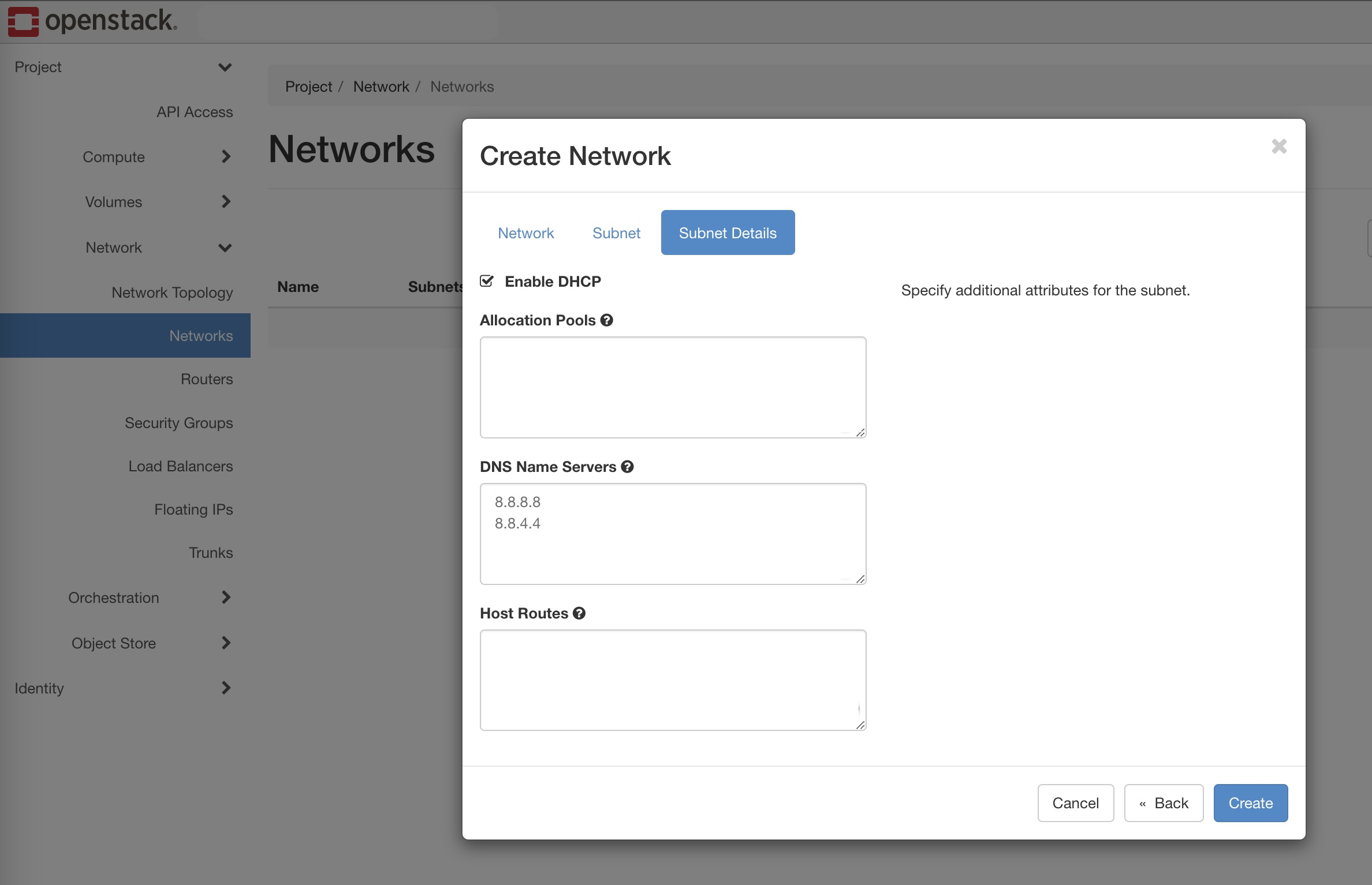
Figure: Subnet Details
Generate Node Token
A one-time node token is required to register a CE Site node to the Distributed Cloud Console. A new token must be generated for every new node in a CE Site. A token is valid for 24 hours. Make sure that the CE node is deployed soon after the token is generated.
The token is included in the cloud-init information under the Content variable. Also included are two variables commented out: slo_ip and slo_gateway. If you are using a static IP address and not DHCP, you must configure these variables and remove the hashtag, to provide an IP address for the VM (node).
-
In Distributed Cloud Console, select the Multi-Cloud Network Connect workspace.
-
Navigate to Manage > Site Management > Secure Mesh Sites v2.
-
For your site, click ... > Generate Node Token.
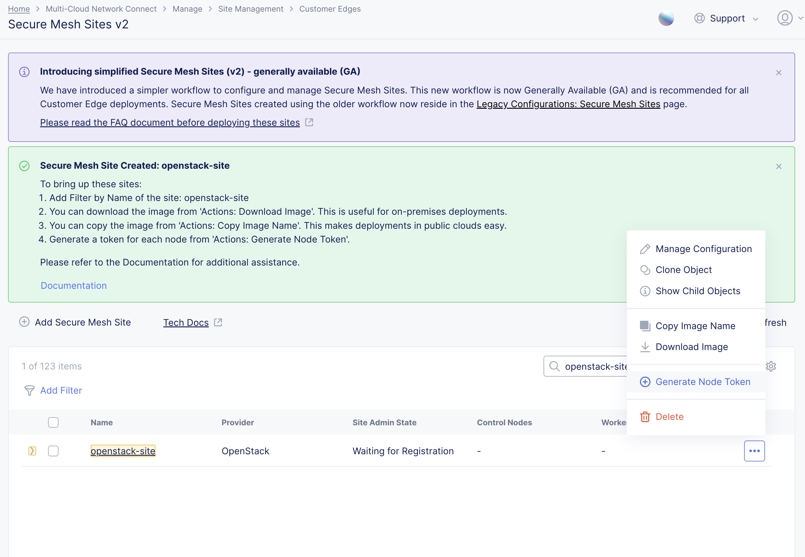
Figure: Node Token
-
Click Copy cloud-init.
-
Save the value locally. This token is used later. The token value is hidden for security purposes.
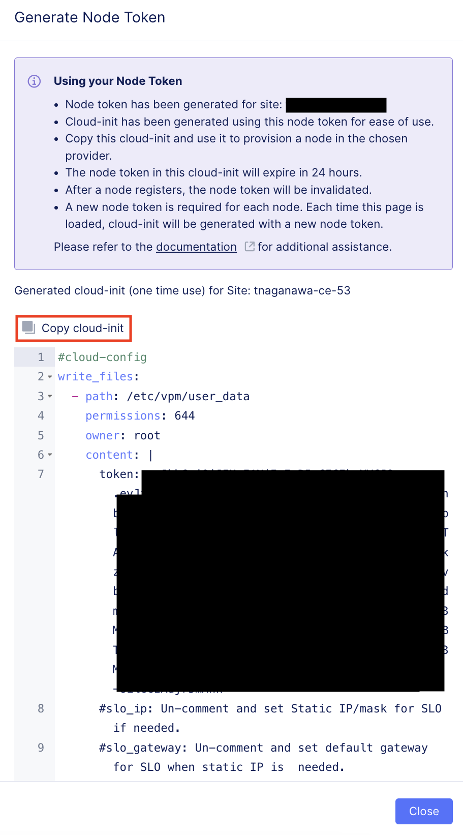
Figure: Copy Node Token
-
Click Close.
-
Generate one token per node you intend to deploy.
-
For static IP address configuration in the cloud-init information, configure the slo_ip and slo_gateway variables and remove the hashtags.
#cloud-configwrite_files: - path: /etc/vpm/user_data permissions: 644 owner: root content: | token: <secret-token-hidden> slo_ip: 10.0.0.5/24 slo_gateway: 10.0.0.1Create OpenStack Virtual Machine
Before deploying a new virtual machine in OpenStack, find your right size and requirements by referring to the Customer Edge Site Sizing Reference guide. For demonstration purposes, the m1.xlarge flavor is used.
Important: The name of the VM should not have "." in it. For example, the hostname can be node-0 or node0, but it cannot be node.f5.com since it is not supported. Your node VM name must adhere to DNS-1035 label requirements. This means the name must consist of lower case alphanumeric characters or “-“, start with an alphabetic character, and end with an alphanumeric character.
If configuring a multi-node site, each node hostname must be unique.
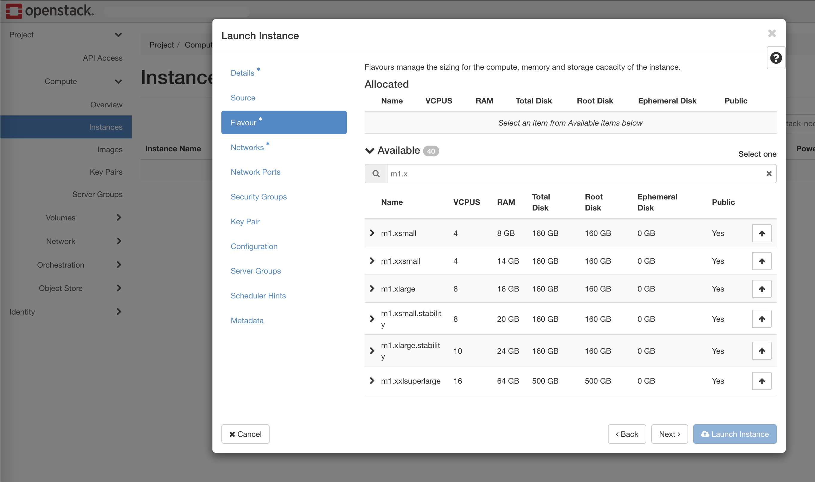
Figure: Instance Types
Step 1: Launch new instance.
-
Navigate to the Compute section in the left-hand menu.
-
Click Launch Instance and fill in the details along with the Availability Zone.
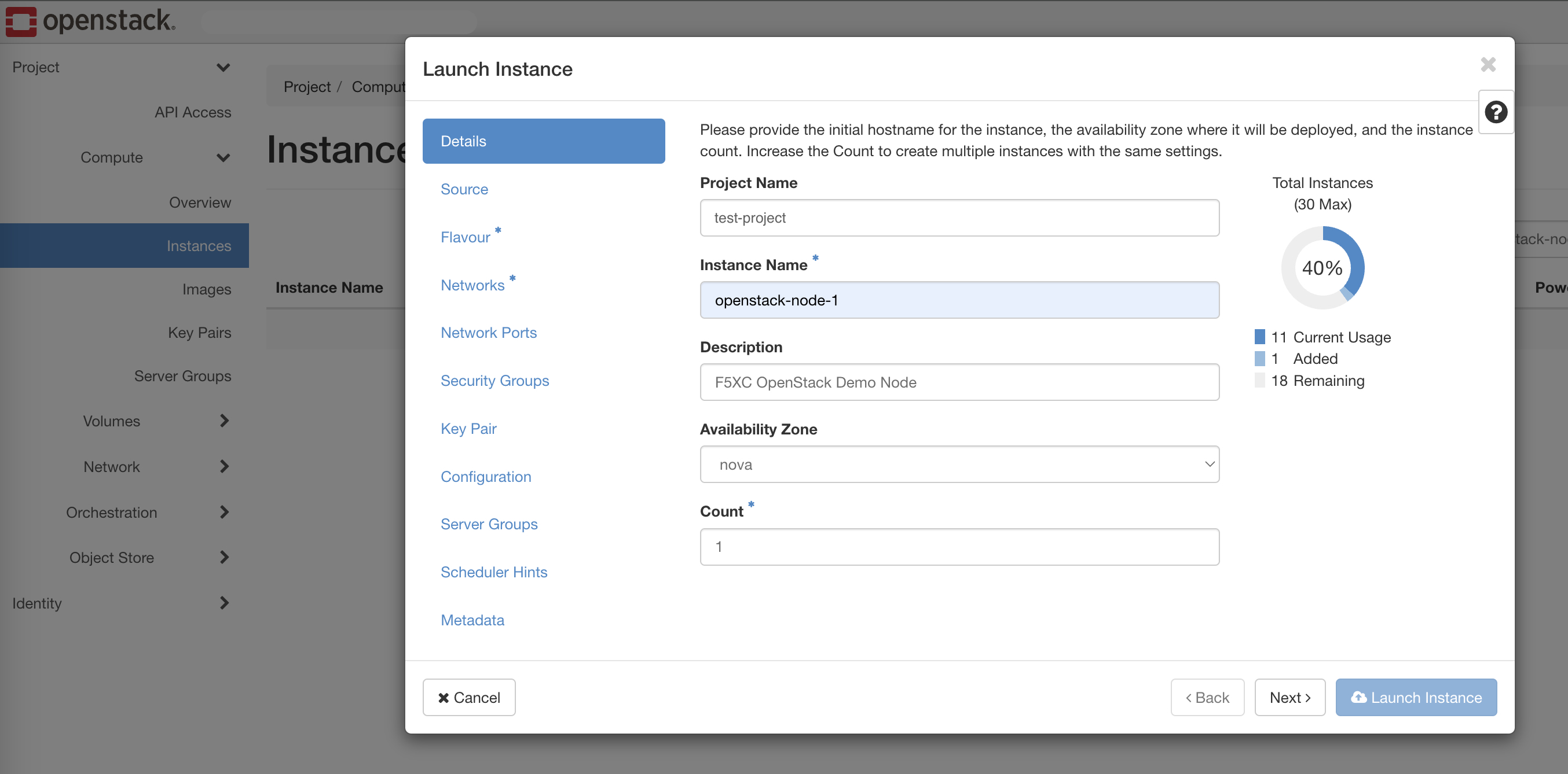
Figure: Launch Instance
Step 2: Select source image.
-
From the Select Boot Source menu, select Image.
-
Select the latest
f5xc-ce-<version>image from the Available list of images and click the up arrow to select it.
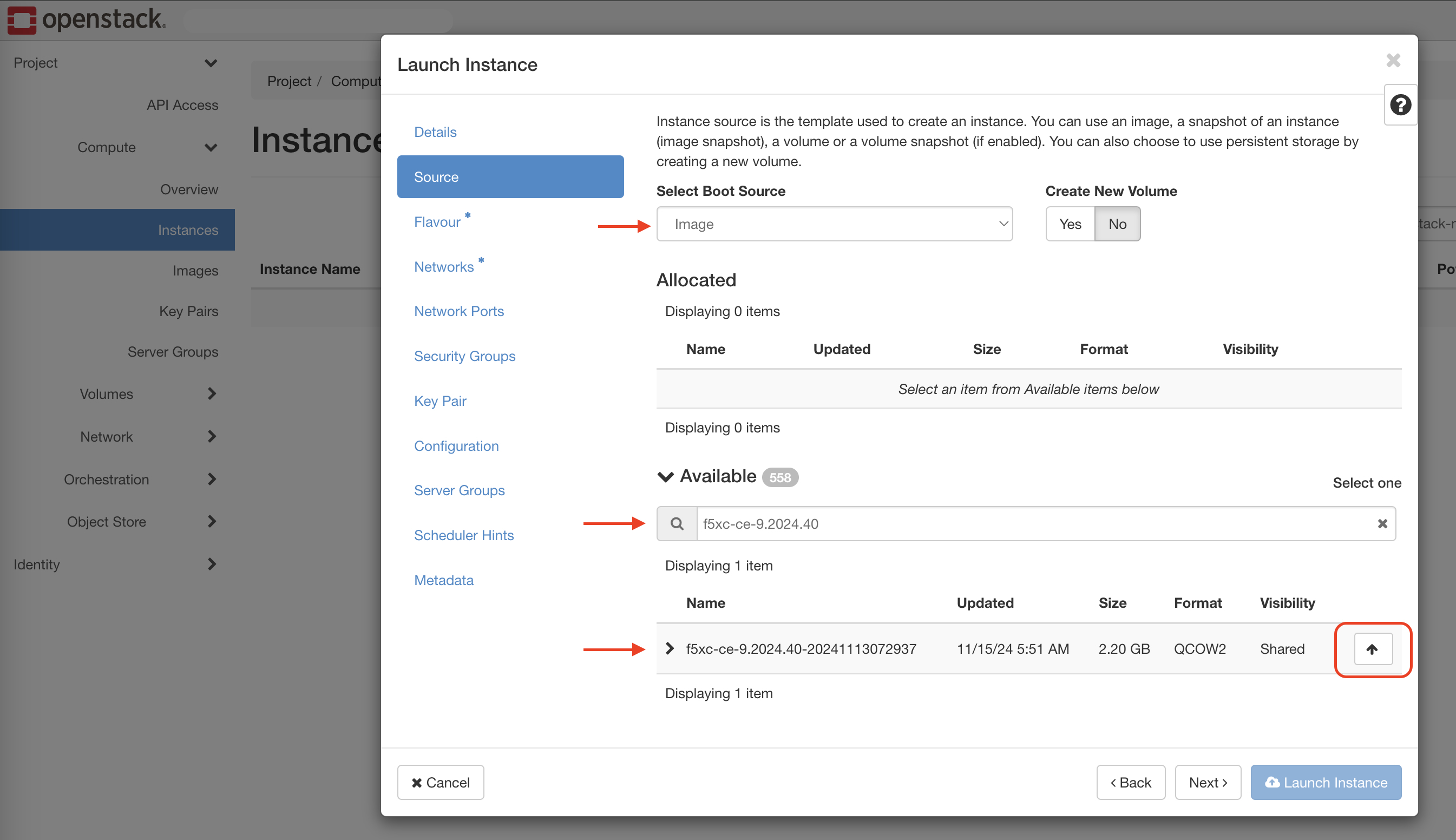
Figure: Boot Source
Step 3: Select flavor for the virtual machine.
-
Select the flavor that meets your requirement. Refer to the Customer Edge Site Sizing Reference guide for recommendations.
-
Click the up arrow to select the flavor.
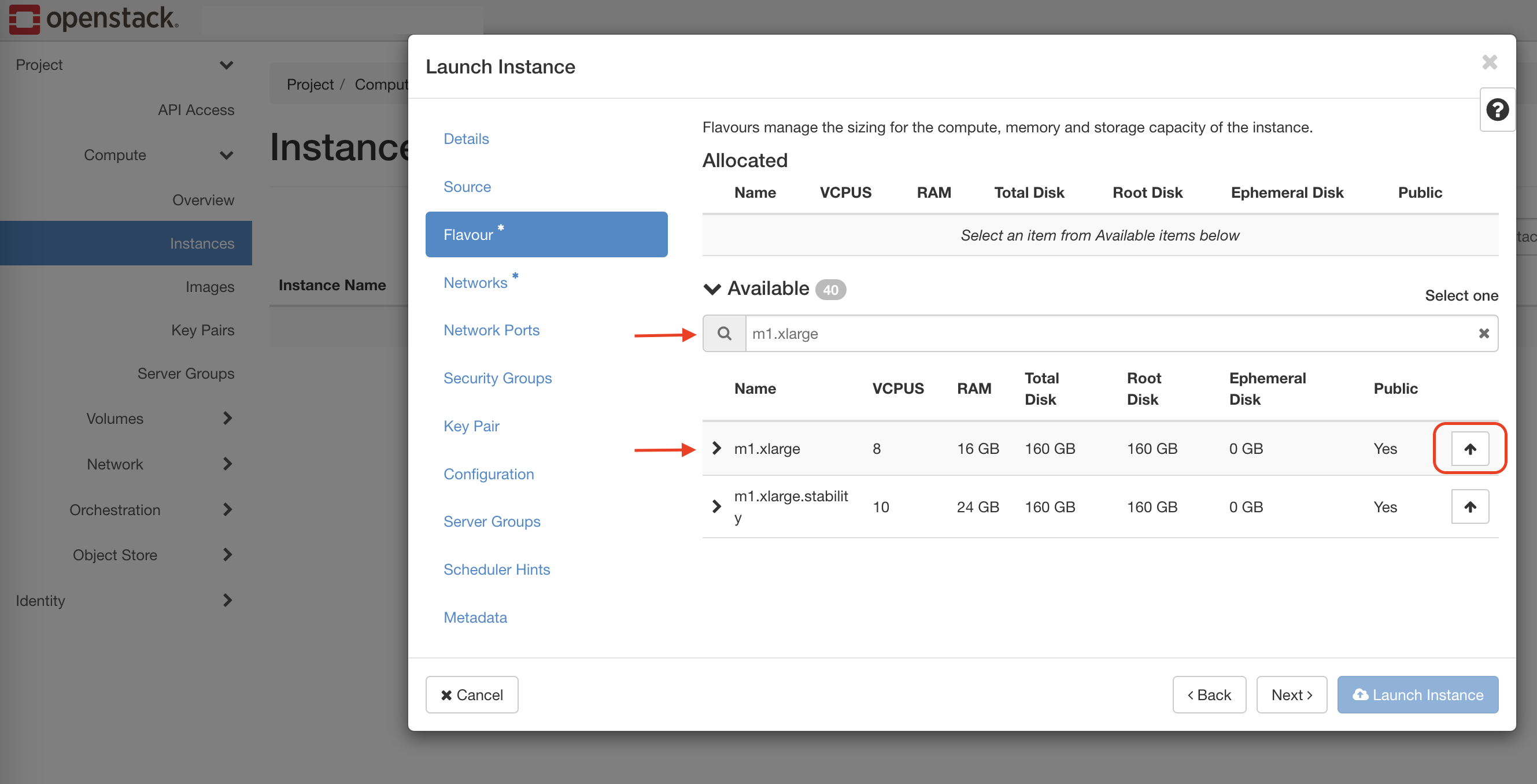
Figure: Image Flavor
Step 4: Select VM network.
-
Navigate to the Networks section.
-
Select the network that was created in the previous section.
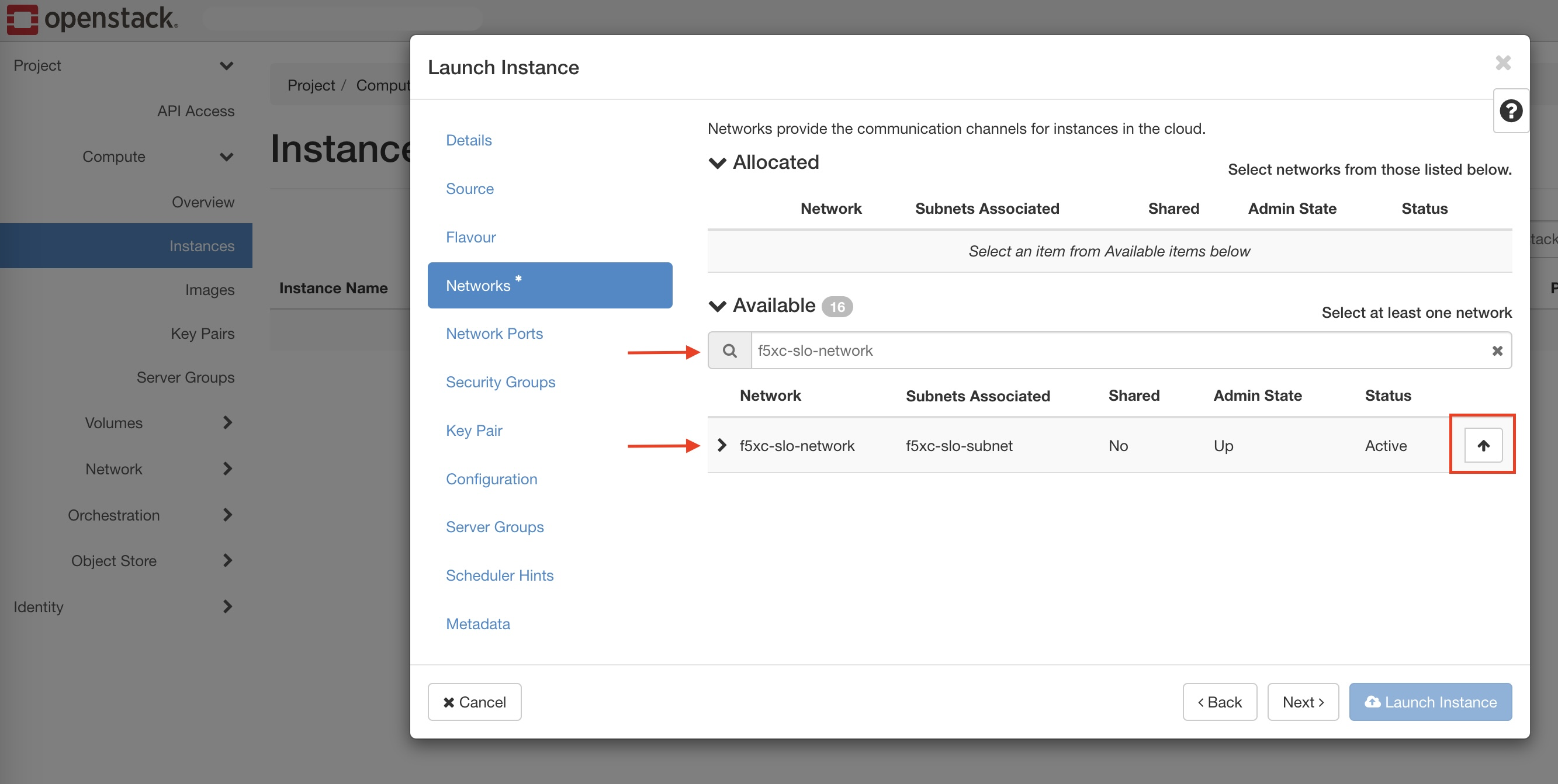
Figure: Instance Network
- You can add additional networks either during VM creation or after it has been launched. However, the primary interface must have Internet connectivity enabled. Ensure the primary network is attached first, followed by the other networks in sequence.
Step 5: Select security groups.
Select the security group that has appropriate inbound and outbound rules, as described in the previous section.
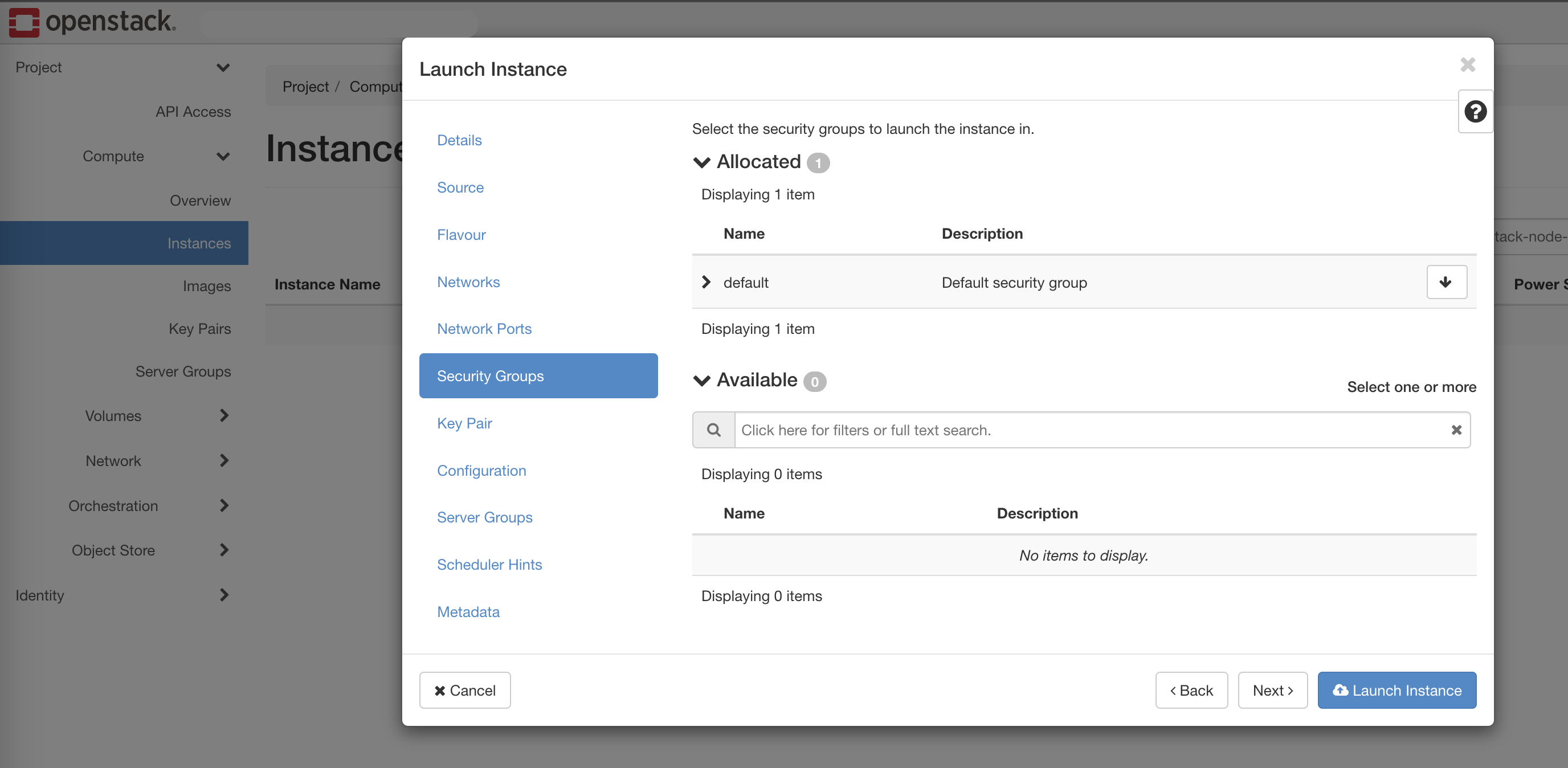
Figure: Instance Security Group
Step 6: Apply the configuration.
-
Navigate to the Configuration section.
-
Copy the cloud-init information (which includes the node token) generated as part of the Generate Node Token section above and paste it in the Customization Script text box.
-
Click Launch Instance.
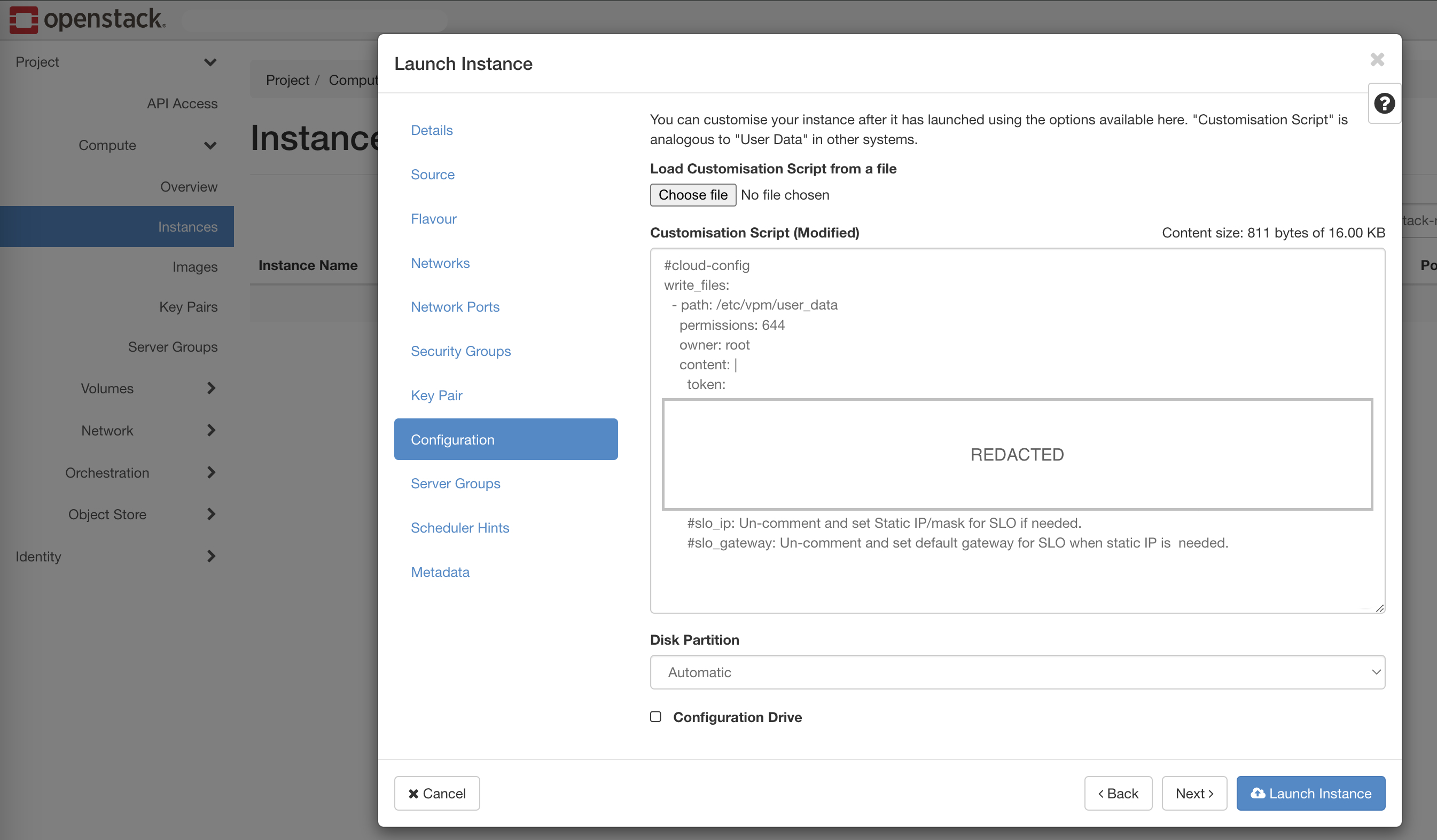
Figure: Instance Configuration
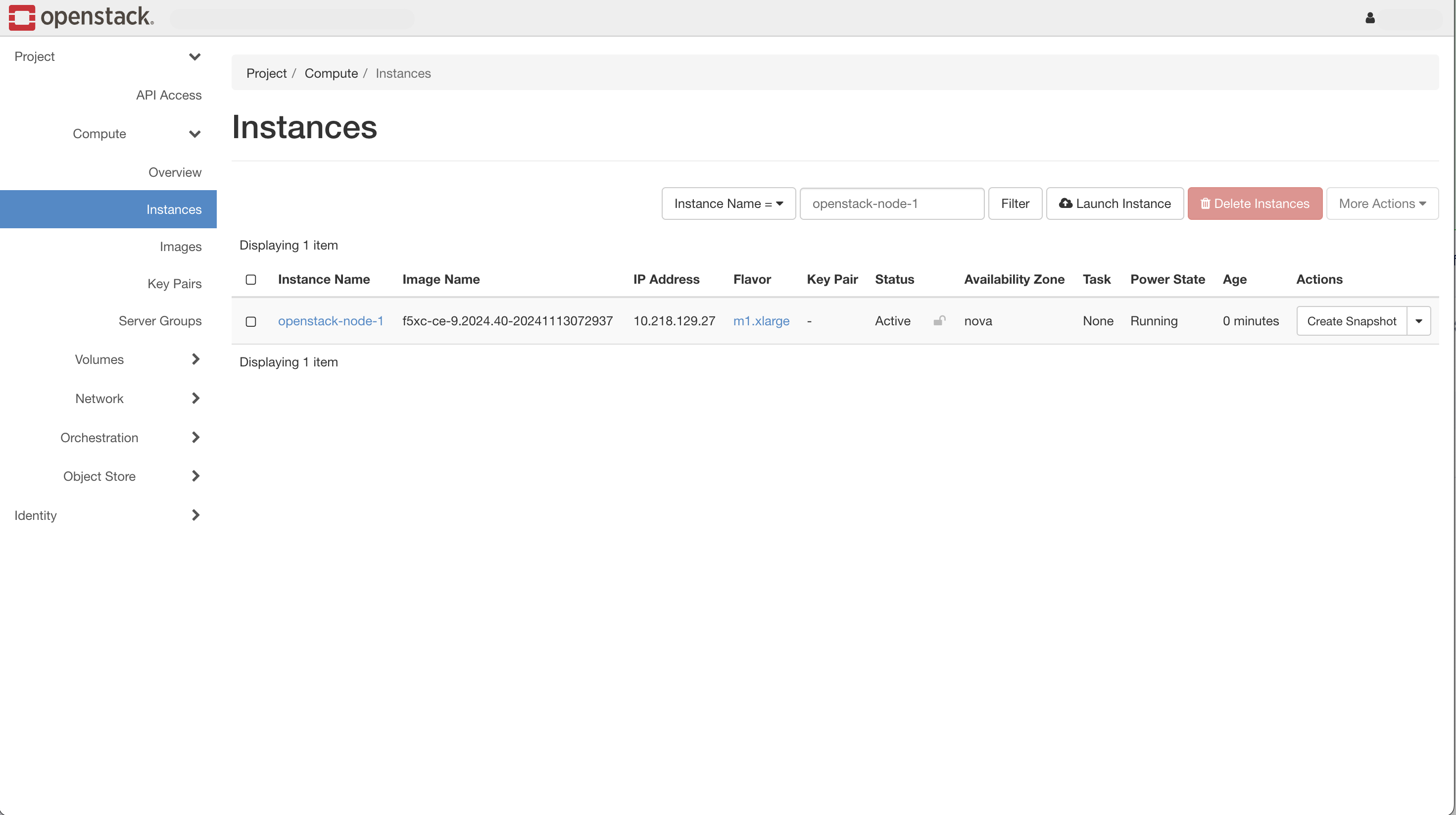
Figure: Instance Node Created
Verify CE Site Registration
-
In Distributed Cloud Console, navigate to Multi-Cloud Network Connect > Overview > Infrastructure > Sites.
-
Select the site. The Dashboard tab should clearly show that the CE Site has registered successfully with the System Health of 100% as well as Data Plane/Control Plane both being up.
-
Select the Infrastructure tab and view the Interfaces table.
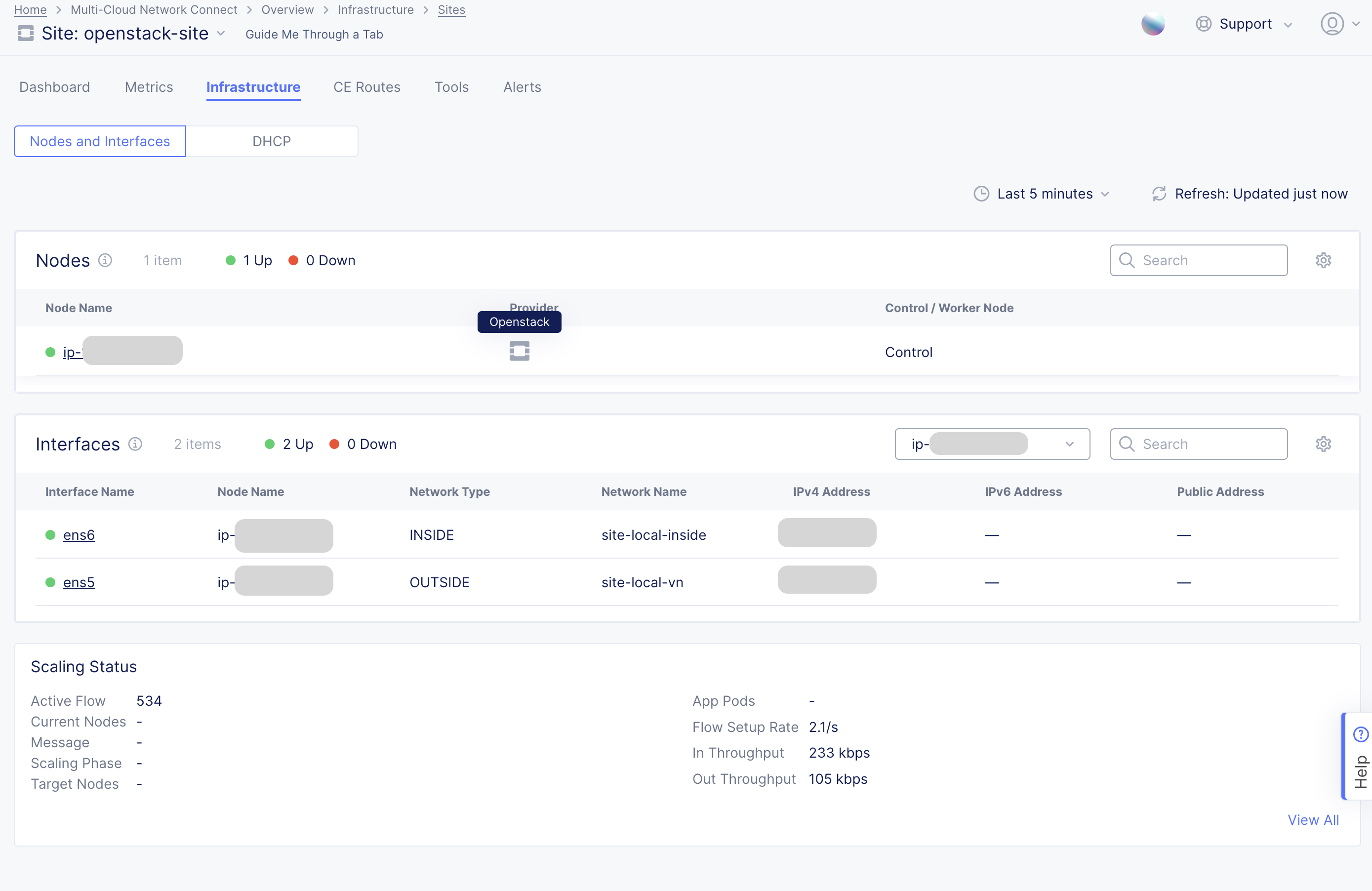
Figure: Verify Interfaces Created
Note: For more information on the site registration process, see the Customer Edge Registration and Upgrade Reference guide.
Manage Network Interfaces (Optional)
After your CE Site registers successfully, you might want to add additional network interfaces to meet your requirements. Ensure that you connect another network interface to the node VM.
Important: Adding or removing network interfaces causes the data plane services on the CE node to restart. Therefore, F5 strongly recommends that you perform this operation during maintenance windows. As data plane services restart, traffic drops are expected, as well as tunnels to F5 Distributed Cloud REs going down.
All CE nodes in a given CE Site should have the same number of network interfaces attached. CE nodes with non-homogenous interfaces within a CE Site might cause issues.
Each node in the CE Site should have interfaces with the same VRFs assigned. For example: If a CE Site has three nodes, each node having two interfaces - the first interface on each node is auto-configured to be in the SLO VRF (to connect to F5 Distributed Cloud). If the second interface on node-1 is in the SLI VRF, then the second interface on node-2 and node-3 must also be in the SLI VRF.
When new interfaces are added, they are auto-discovered. You can configure the interface (for example: place the interface in the appropriate VRF) from the CE Site configuration.
The first interface of the CE nodes should not be removed or modified.
After you configure the SLO interface with a static IP address, DHCP will still be displayed in the Console. However, your static IP configuration is well taken into account. Also, remember that you cannot modify SLO parameters once the node is registered and deployed.
Add New Interface
Step 1: Shutdown VM instance.
Stop the VM instance before attaching a new interface as recommended. Note that the site health drops to 0 when the nodes are stopped. Therefore, you should perform this operation during a scheduled maintenance window.
- Navigate to your node in OpenStack. Under Actions, select Shut Off Instance.
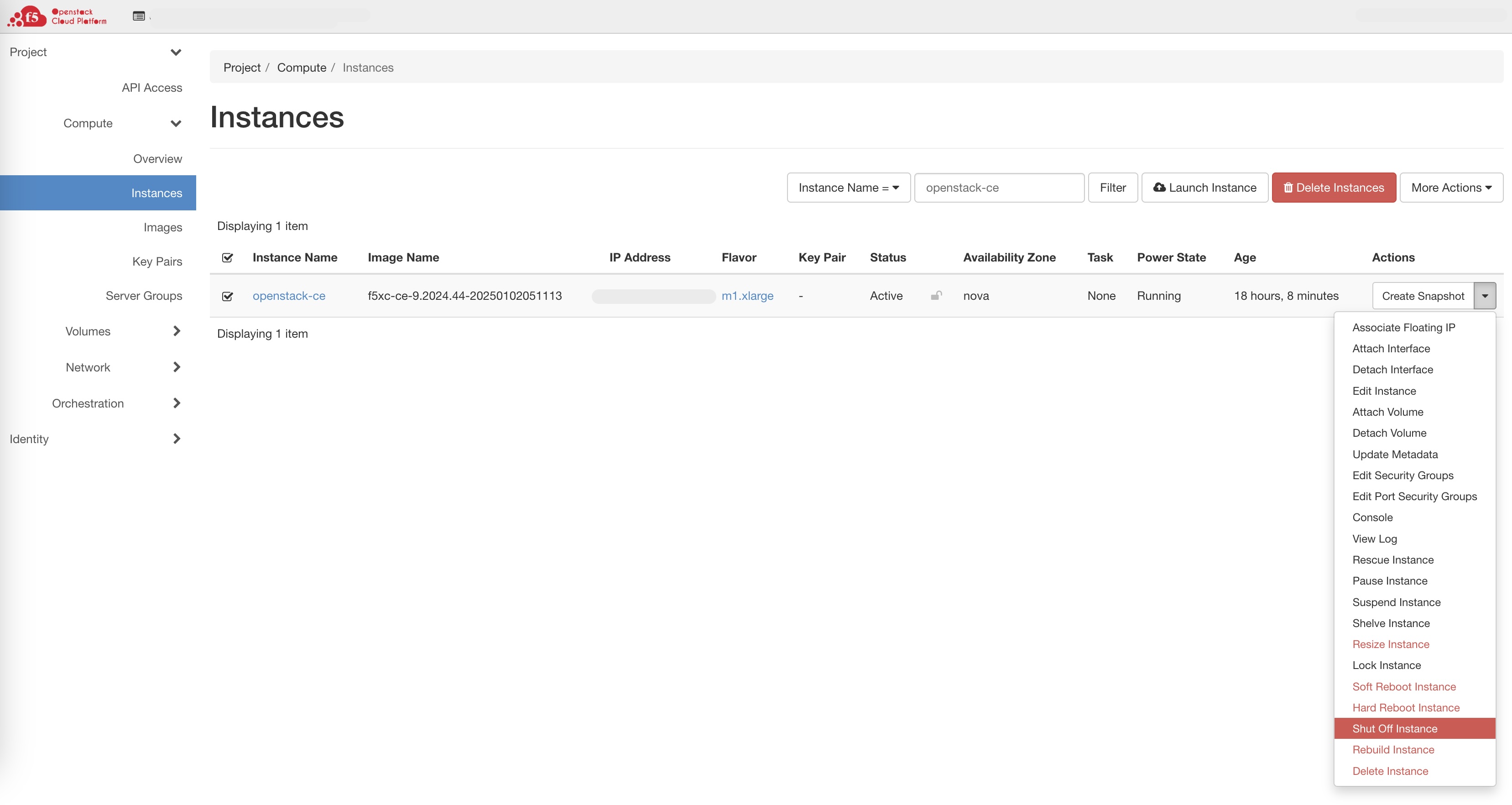
Figure: Shutdown VM Instance
- In Distributed Cloud Console, confirm that the Site Health is down to 0.
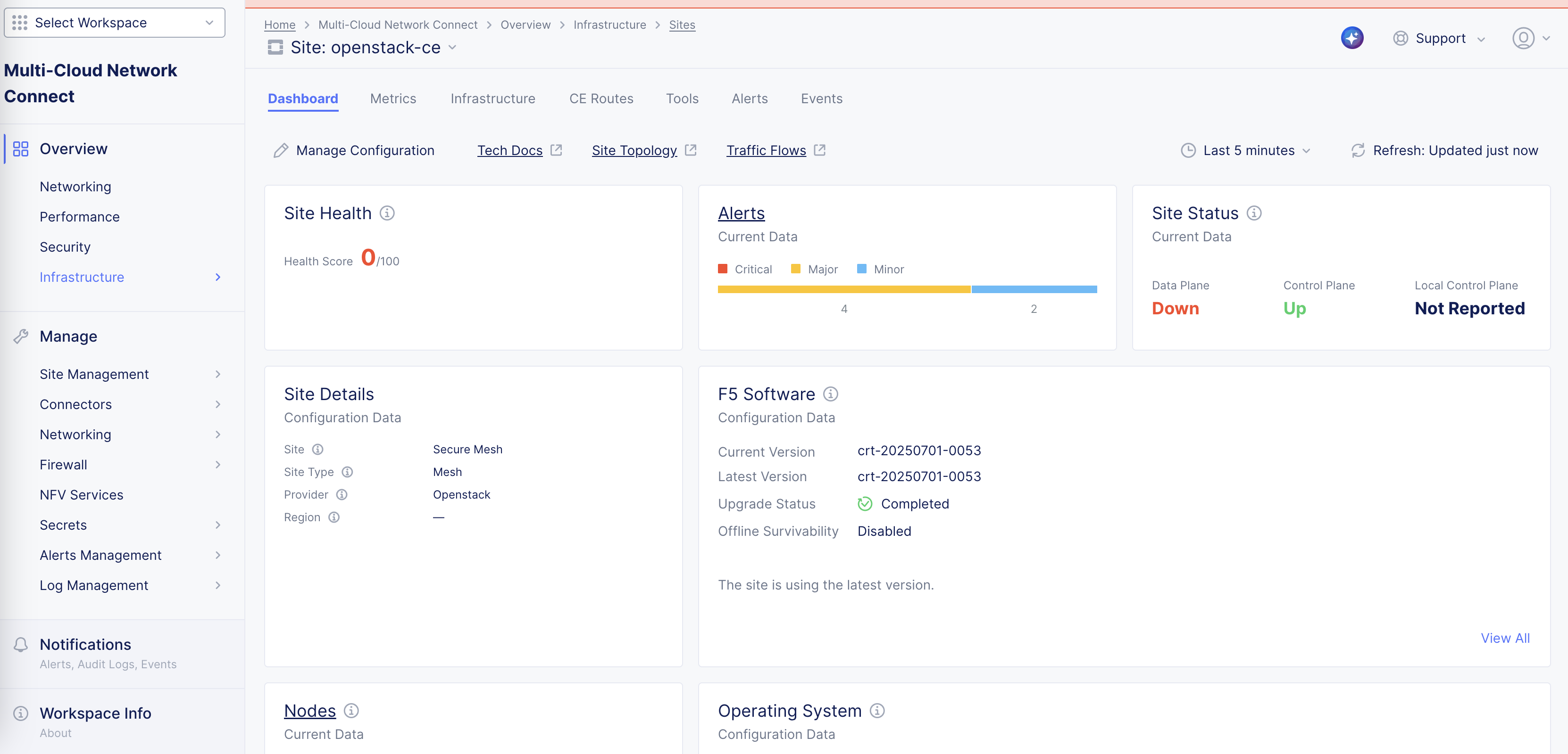
Figure: Site Health
Step 2: Attach new interface.
- In OpenStack, under Actions for your node, select Attach Interface from the drop-down menu.
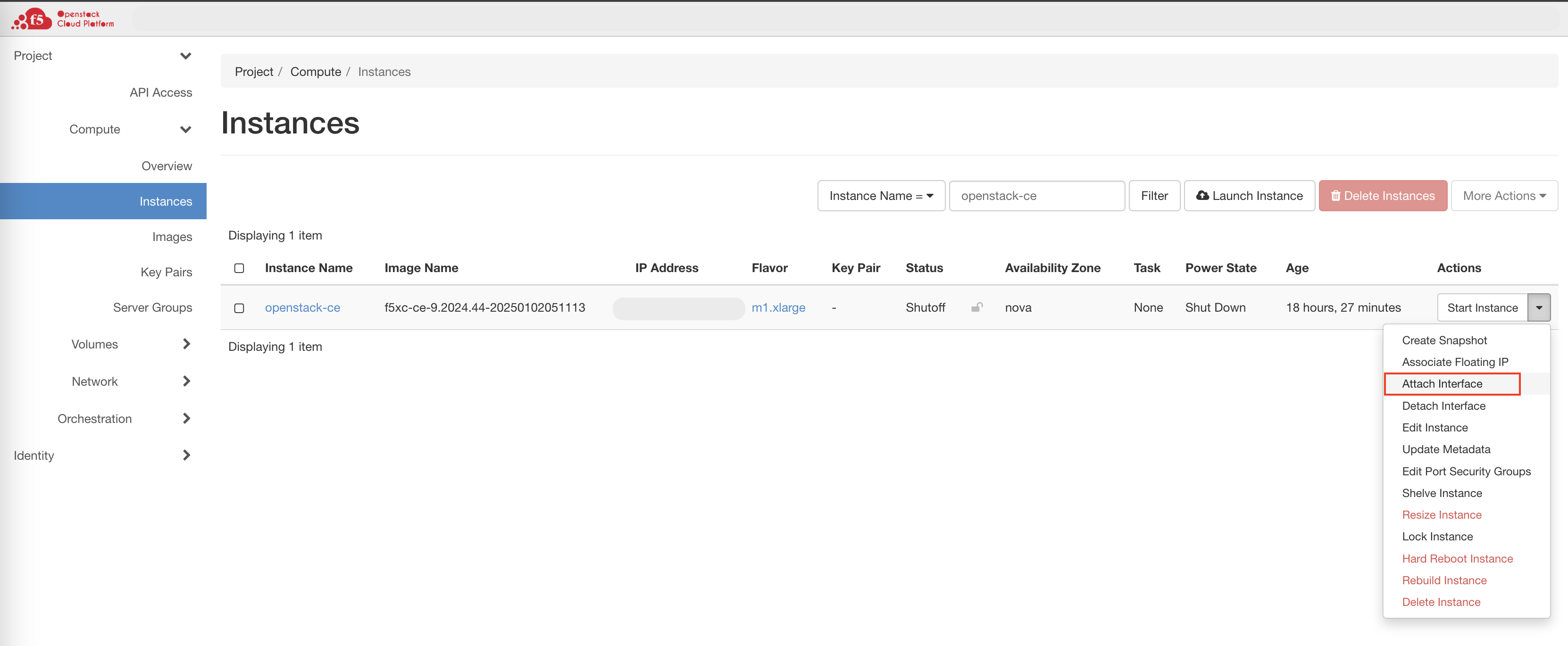
Figure: Attach Interface
- Select the new interface from the drop-down menu.
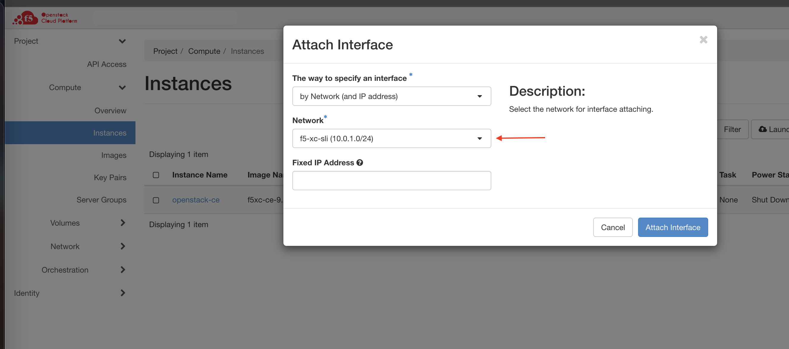
Figure: Select Interface
- Confirm that the new interface is attached to your node.
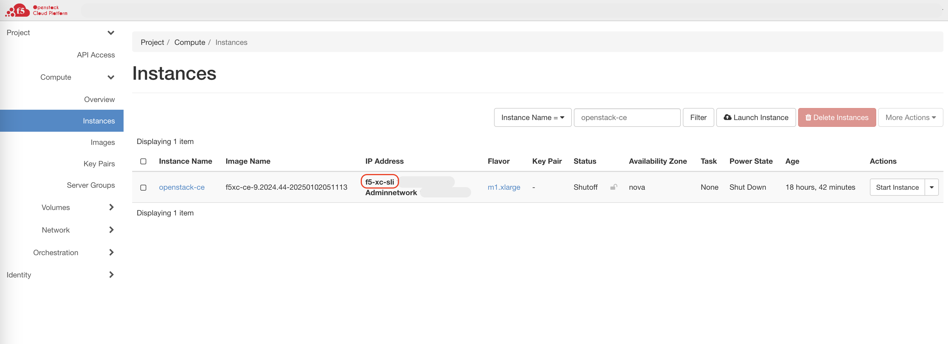
Figure: Confirm Interface Attached
Step 3: Start the node.
- Select Start Instance.
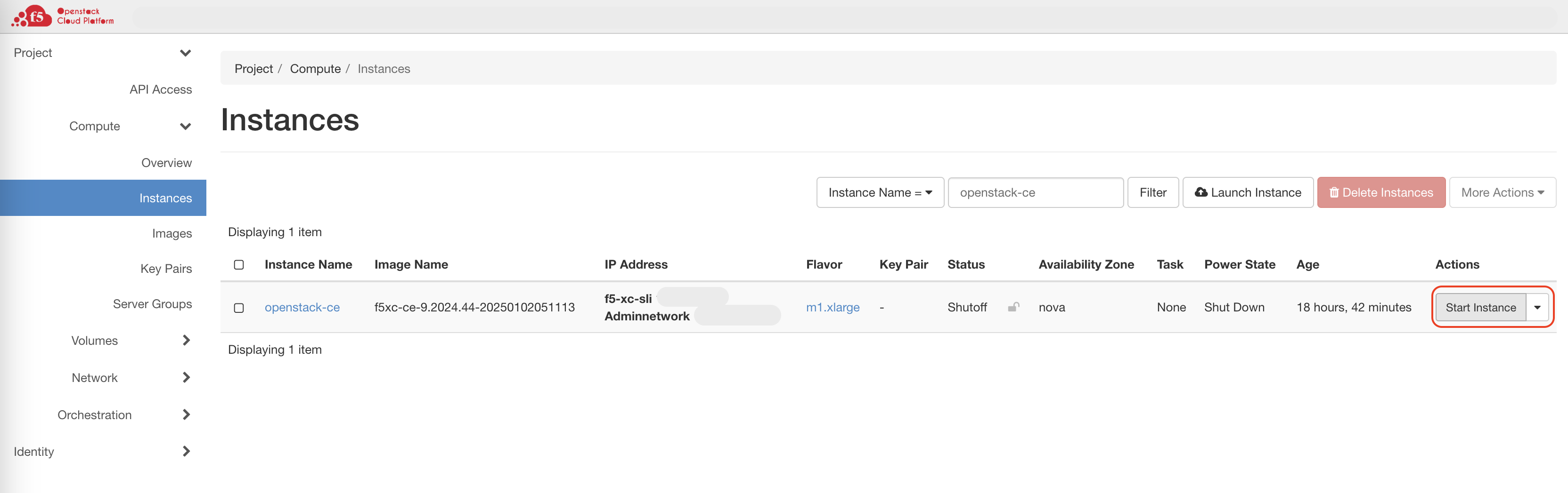
Figure: Start Node
- Verify that the node’s Power State is back to the Running mode.
Step 4: Confirm Site health.
In Distributed Cloud Console, verify that the node recognized the new interface in the Site’s Infrastructure tab and is 100% healthy.
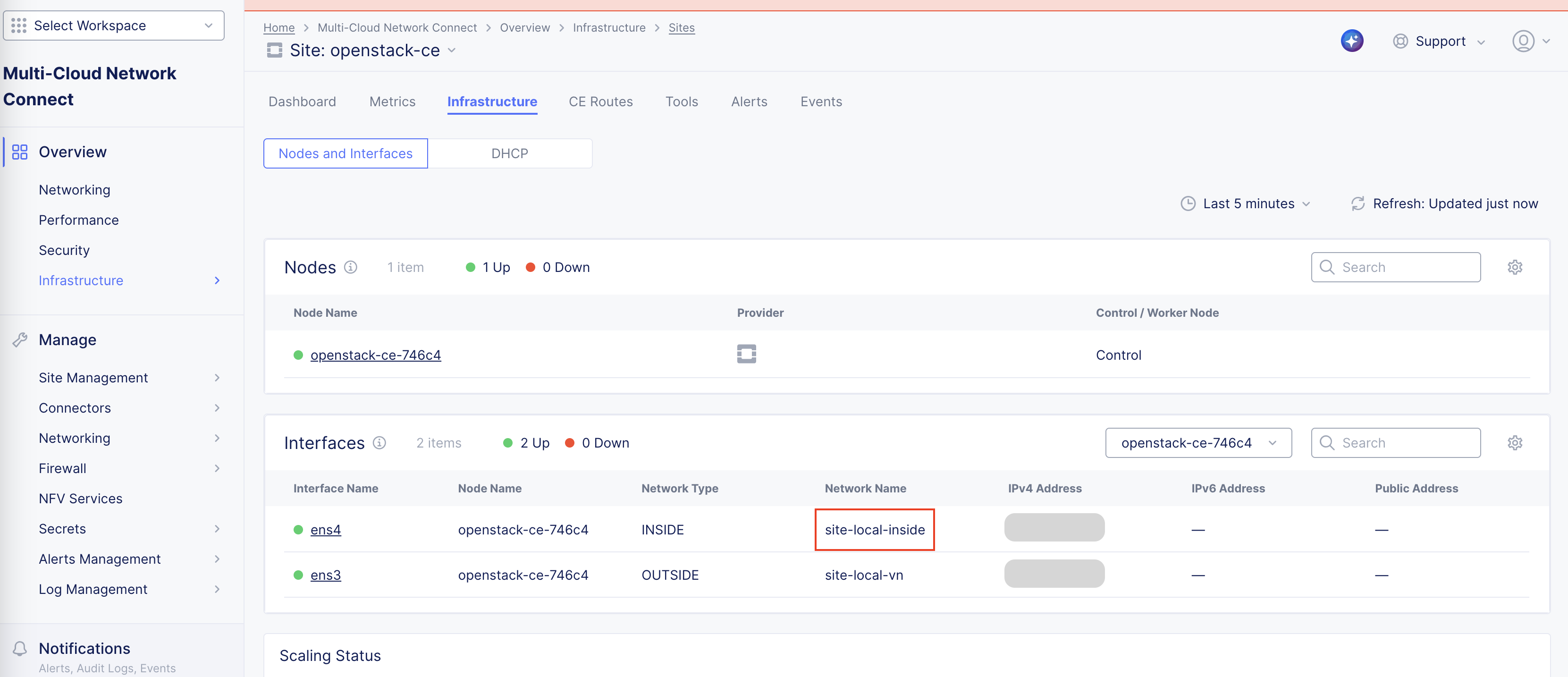
Figure: Verify Site Health
Day 2 Operations
- To monitor your Site, see the Monitor Site guide.
- To manage your Site software and OS updates, see the Manage Site guide.
- For troubleshooting issues, see the Troubleshooting Guide for Secure Mesh Site v2 Deployment guide. It provides step-by-step instructions to debug and resolve the issues that may arise due to registration and provisioning errors.
- For the latest on Distributed Cloud Services releases, see Changelogs.
- To view the various types of events generated, see the Events Reference guide.
Related Guides
To create a load balancer on the CE Site, see the HTTP Load Balancer or the TCP Load Balancer guides.
Concepts
On this page:
- Objective
- Planning
- General Prerequisites
- Configuration Overview
- Procedure
- Create Site Object
- Create a Network Security Group
- Download and Create Node Image
- Configure Network Settings
- Generate Node Token
- Create OpenStack Virtual Machine
- Verify CE Site Registration
- Manage Network Interfaces (Optional)
- Add New Interface
- Day 2 Operations
- Related Guides
- Concepts