Deploy Secure Mesh Site v2 in GCP (ClickOps)
Objective
This guide provides instructions on how to create a customer edge (CE) site using F5® Distributed Cloud Console and Google Cloud Platform (GCP) Console and deploy to a GCP virtual private cloud (VPC).
Important: This guide does not provide instructions on how to deploy an F5® App Stack Site.
Planning
Read the following documents before deploying a Secure Mesh Site in any provider environment:
- Understanding F5 Distributed Cloud - Customer Edge (CE)
- CE Datasheet
- CE Supported Platforms Guide
- Customer Edge Site Sizing Reference
- CE Performance Guide: Contact your account representative on CE performance-related information.
- Proxy for CE Registration and Upgrades Reference
- Secure Mesh Sites v2 Frequently Asked Questions
- Customer Edge Registration and Upgrade Reference
- F5 Customer Edge IP Address and Domain Reference for Firewall or Proxy Settings
General Prerequisites
The following general prerequisites apply:
-
A Distributed Cloud Services Account. If you do not have an account, see Getting Started with Console.
-
An account with GCP with permissions to create objects in Compute Engine, VPC Networks, Network Services, and Cloud Storage services. See Policies and Permissions Reference for permissions needed to deploy site.
-
A GCP Storage Bucket where the CE image file can be uploaded.
-
Resources required per node: Minimum 8 vCPUs, 32 GB RAM, and 80 GB disk storage. For a full listing of the resources required, see the Customer Edge Site Sizing Reference guide. All the nodes in a given CE Site should have the same resources regarding the compute, memory, and disk storage. When deploying in cloud environments, these nodes should use the same instance flavor.
-
Allow traffic from and to the Distributed Cloud public IP addresses to your network and allowlist related domain names. See F5 Customer Edge IP Address and Domain Reference for Firewall or Proxy Settings guide for the list of IP addresses and domain names.
-
The new Secure Mesh Site workflow enables you to have up to eight (8) interfaces. However, these interfaces should be in different VPCs. Therefore, make sure you have the required VPC with subnets with non-overlapping CIDRs available before creating the CE Site nodes.
-
Internet Control Message Protocol (ICMP) needs to be opened between the CE nodes on the Site Local Outside (SLO) interfaces. This is needed to ensure intra-cluster communication checks.
Important: After you deploy the CE Site, the IP address for the SLO interface cannot be changed. Also, the MAC address cannot be changed.
IAM Required Roles
To perform the steps provided in this guide and launch a CE instance on GCP, you must be part of the Service Account that has the following roles:
- roles/config.agent
- roles/compute.admin
- roles/iam.serviceAccountUser
You must also have the following roles:
- Editor
- ComputeInstanceAdmin(v1)
Configuration Overview
To create a Secure Mesh Site with GCP, here are the high-level steps:
- Site object configuration: Create and configure a Secure Mesh Site object using F5 Distributed Cloud Console.
- Node creation prerequisites: Create objects that are associated with the CE nodes, including VPC subnets, firewall rules, and more.
- Node management: Use Launch Instance deployment method to create the CE nodes. Each CE node is a virtual machine (VM).
- Network interface management: Add additional interfaces on the nodes, if necessary.
Procedure
In this guide, the procedure demonstrates the steps to deploy a single-node secure mesh site with dual interfaces. However, this guide also explains the necessary deviations from this specific model where necessary, making it flexible to adjust to different node and interface requirements.
Create Site Object
The steps below show the minimum required configurations for creating a GCP Site. To understand the complete set of configuration options, refer to the Create Secure Mesh Site guide.
Step 1: Open the site creation wizard.
-
In the Multi-Cloud Network Connect workspace, navigate to Manage > Site Management > Secure Mesh Sites v2.
-
Select Add Secure Mesh Site to open the configuration form.
Step 2: Enter metadata information for your Site.
-
In the Metadata section, enter a name for your Site.
-
Optionally, select labels and add a description.
Step 3: Select the infrastructure provider settings for Site.
Set the Provider Name option to GCP.
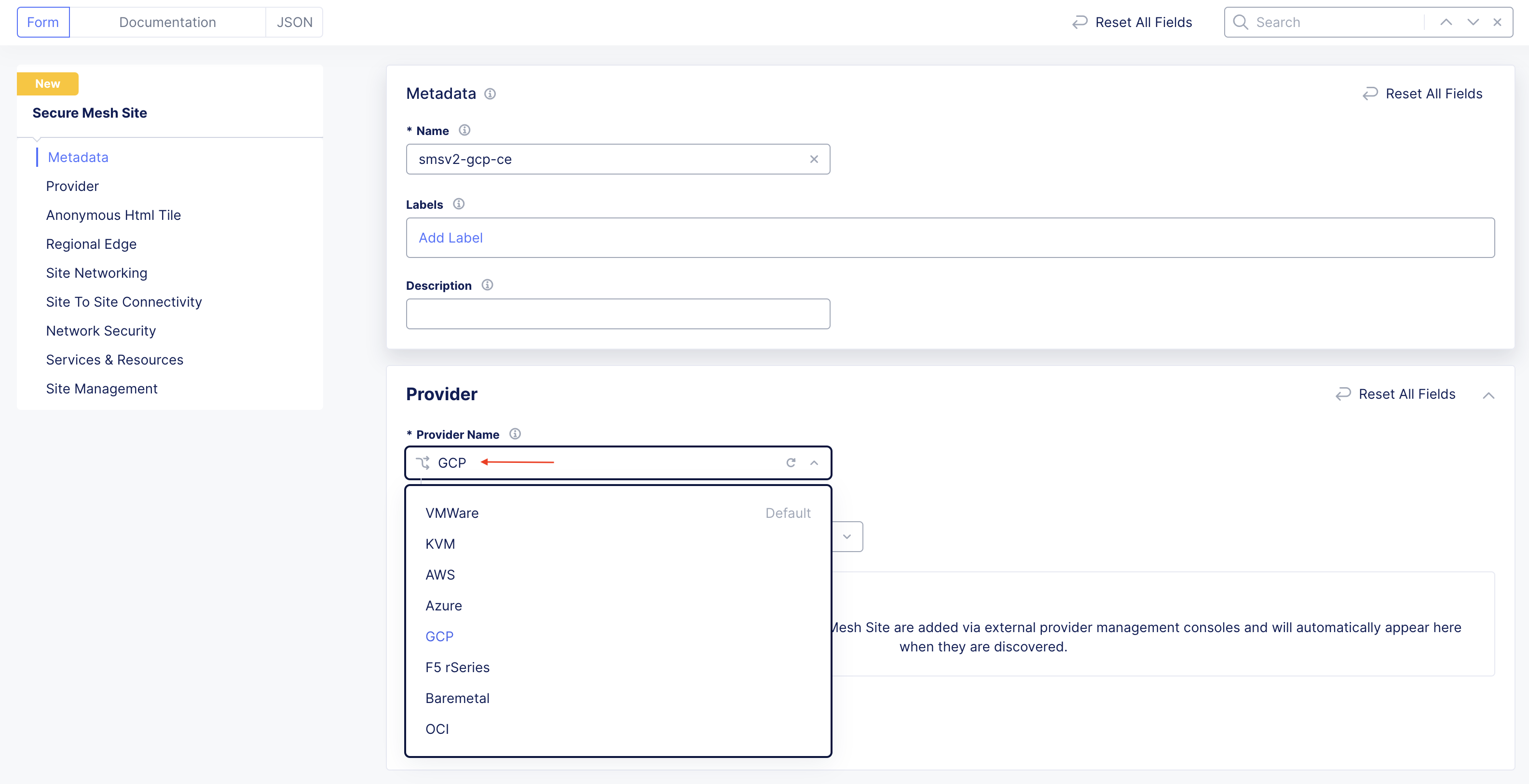
Figure: Provider Type
Step 4: Select the HA mode.
For High Availability, choose an option. If it is Disabled, then the CE Site only supports one node. If it is Enabled, the CE Site requires three nodes. Additional nodes can only be added to CE sites when HA is Enabled.
Important: The High Availability mode cannot be changed after the CE Site is created.
Step 5: Save the configuration.
-
Leave the other options with their default values. These options have intelligent default values and do not need further configuration. Refer to the Create Secure Mesh Site guide for more information on these options.
-
Click Add Secure Mesh Site.
Create VPC Networks and Subnets
Create two VPC networks, with one subnet each for the SLO and SLI interfaces. Note that this procedure creates a two-interface CE Site.
Step 1: Create SLO VPC and subnet.
- In GCP Console, navigate to VPC networks and click Create VPC network.
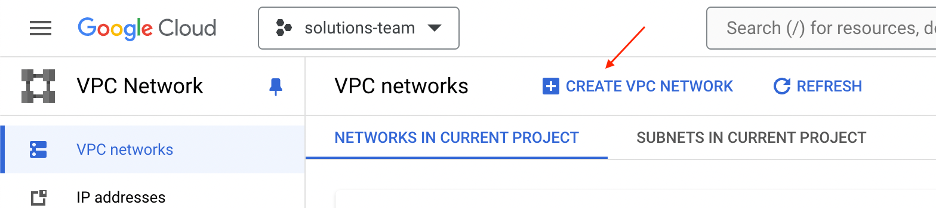
Figure: SLO Subnet
- In the Name field, specify the new network name.
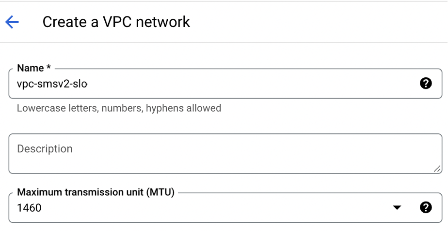
Figure: SLO Subnet Name
-
For Subnet creation mode, select Custom.
-
Enter a subnet name, select the region, and ensure IPv4 (single-stack) is selected.
-
Enter an IPv4 range.
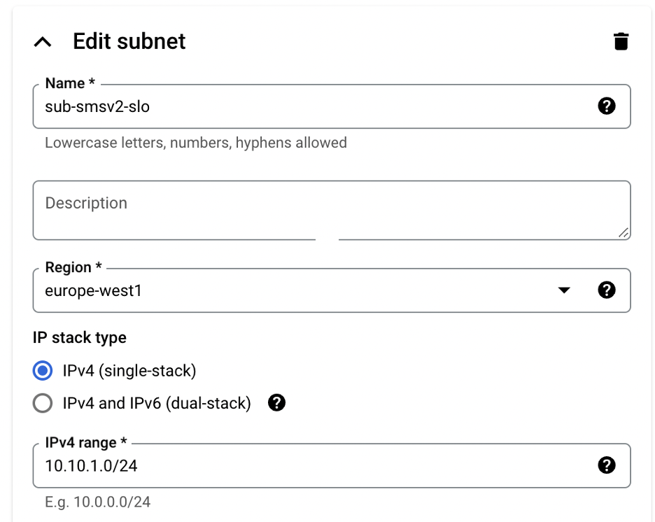
Figure: SLO Subnet Custom
-
Skip the firewall rule configurations, as this is configured in the next section.
-
Keep the rest of the default options.
-
Click Create.
Step 2: Create SLI VPC and subnet.
Repeat the previous steps to create the SLI VPC and subnet. However, use the following parameters (as examples):
- VPC name: vpc-smsv2-sli
- Subnet name: sub-smsv2-sli
- IPv4 range: 10.10.2.0/24
Step 3: Optionally, add additional VPCs and subnets
If you need more than two interfaces for your CE Site, you must create new VPCs and subnets for each network interface. This is optional. The CE Site does not require additional interfaces for regular operations. Each additional network interface becomes an SLI interface.
To create new interfaces, repeat the steps above and use a non-overlapping IP address range. As an example, you can use the following parameters (as examples):
- VPC name: vpc-smsv2-sli2
- Subnet name: sub-smsv2-sli2
- IPv4 range: 10.10.3.0/24
Configure Firewall Rules
The CE data path automatically manages the ports and protocols allowed on the interfaces. Therefore, you need to create allow-all rules to use with the CE Site nodes.
Step 1: Add rules for SLO network.
- In GCP Console, navigate to VPC networks and click on the new SLO network created previously.
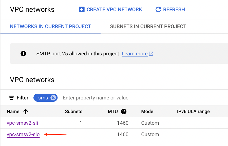
Figure: SLO Subnet Selection
- In the Firewalls tab, click Create VPC firewall rule and create any-to-any allow-all traffic ingress and egress rules as shown in image. Make sure you add a tag to match the Targets where the rule is applied. The network interfaces of the CE Site node are configured with the same tag to apply the rules to it.
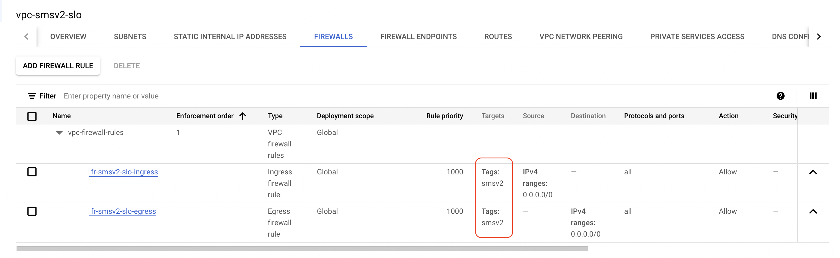
Figure: SLO Firewall Rules
Step 2: Add rules for SLI network.
Repeat the steps above for the SLI VPC network and add allow-all rules.
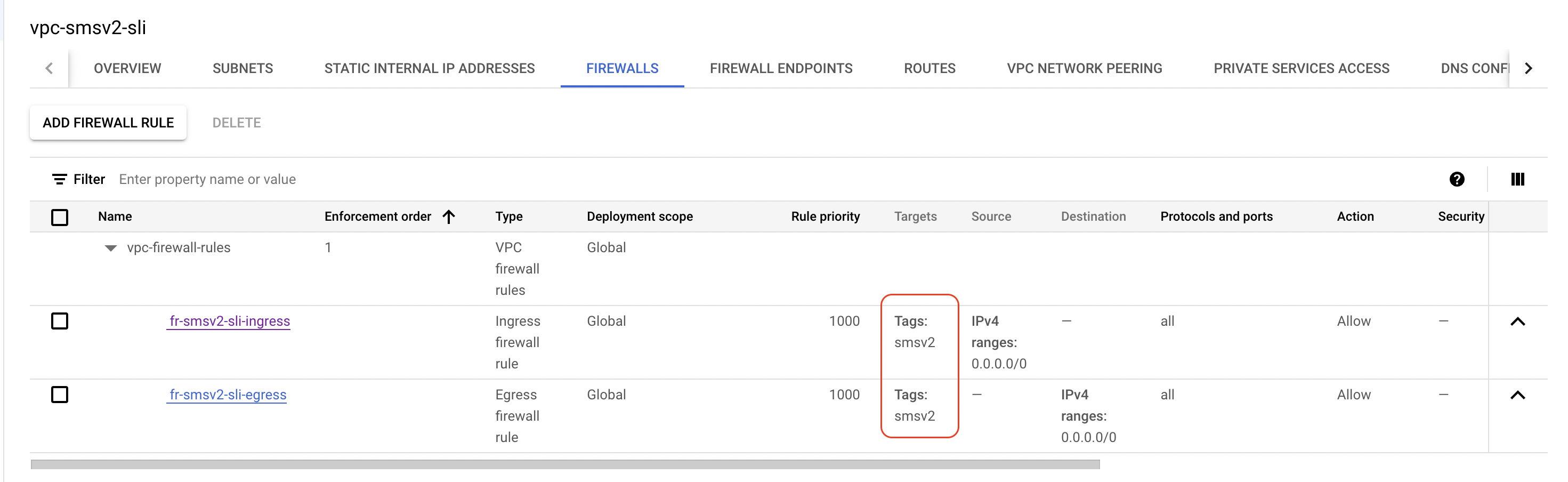
Figure: SLI Firewall Rules
Reserve External IP Address
An external IP address is required to enable your CE to connect to the F5 Distributed Cloud Services.
-
In GCP console, navigate to VPC networks > IP addresses.
-
Click Reserve external.
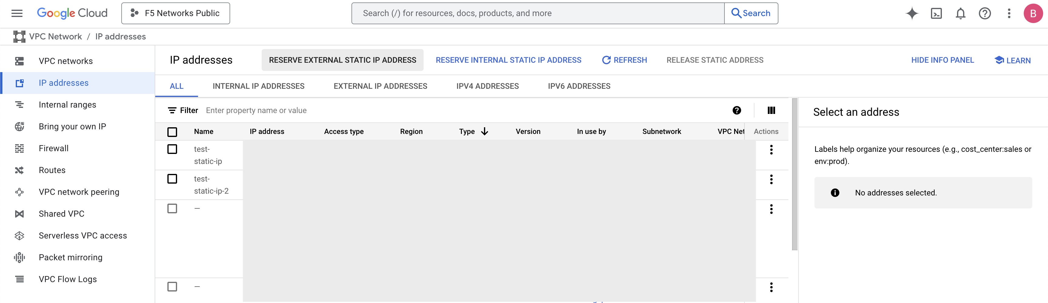
Figure: Reserve External IP Address
-
Provide the name.
-
Select the Network Service Tier as Standard or Premium based on the project-level default.
-
Select the IP version as IPv4.
-
Select the Type as Regional and select the same region used to create the VPC network in the previous step.
-
Leave the Attached to field as blank as you need to eventually attach the IP address to the CE when you launch the instance.
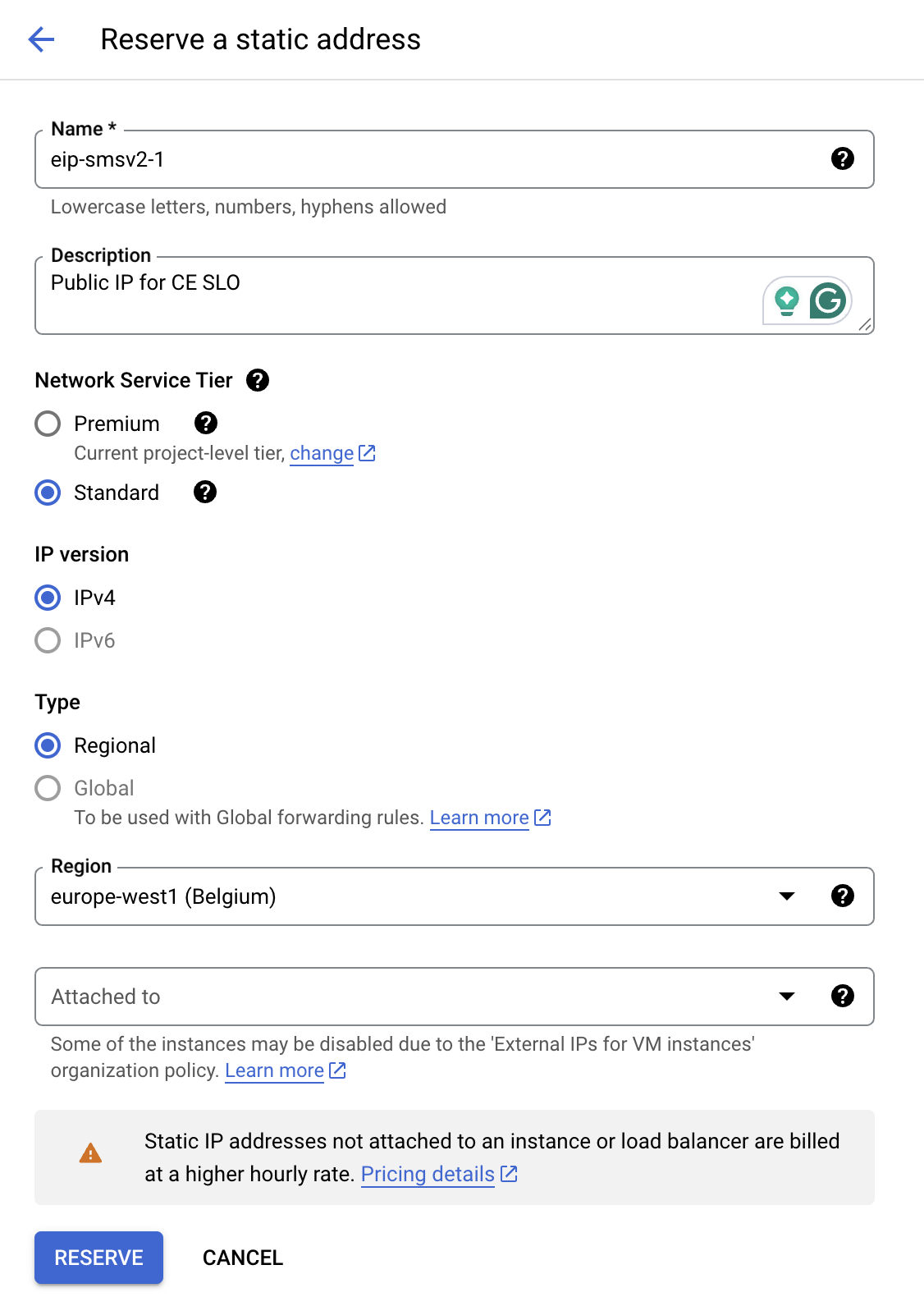
Figure: Configure Reserve External IP Address
- Click Reserve.
Generate Node Token
A one-time node token is required to register a CE Site node to the Distributed Cloud Console. A new token must be generated for every new node in a CE Site. A token is valid for 24 hours. Make sure that the CE node is deployed soon after the token is generated.
-
In Distributed Cloud Console, select the Multi-Cloud Network Connect workspace.
-
Navigate to Manage > Site Management > Secure Mesh Sites v2.
-
For your site, click ... > Generate Node Token.
-
Click Copy Token.
-
Save the value locally. This token is used later.
-
Click Close.
-
Generate one token per node you intend to deploy.
Create GCP Virtual Machine
You can use one of two methods to create the virtual machine (VM). You can (1) deploy directly from GCP Marketplace, or (2) deploy using a downloaded file. Each VM is a node in your Site.
Important: The name of the VM should not have "." in it. For example, the hostname can be node-0 or node0, but it cannot be node.f5.com since it is not supported. Your node VM name must adhere to DNS-1035 label requirements. This means the name must consist of lower case alphanumeric characters or “-“, start with an alphabetic character, and end with an alphanumeric character.
If configuring a multi-node site, each node hostname must be unique.
Launch Node VM Instance from GCP Marketplace
This section guides you through the procedure to deploy directly from GCP Marketplace using a public image published by F5. F5 recommends this method to deploy your CE Site nodes.
Step 1: Create new virtual machine.
-
In Distributed Cloud Console, select the Multi-Cloud Network Connect workspace.
-
Navigate to Manage > Site Management > Secure Mesh Sites v2.
-
For your site, click ... > Launch Instance. This action opens the CE image listing on GCP Marketplace, in a new browser tab.
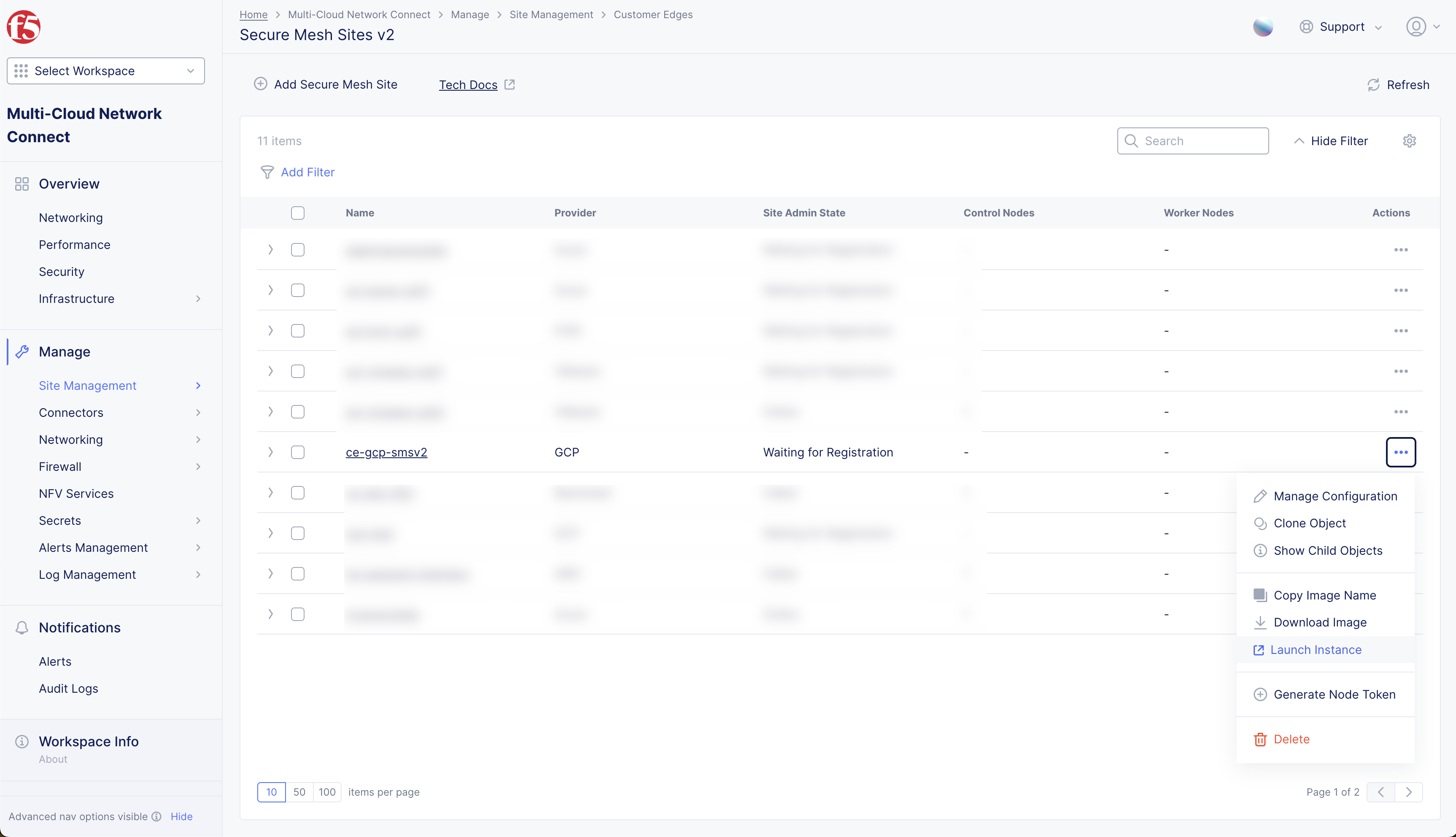
Figure: Launch Instance for Marketplace Listing
- Click Launch.
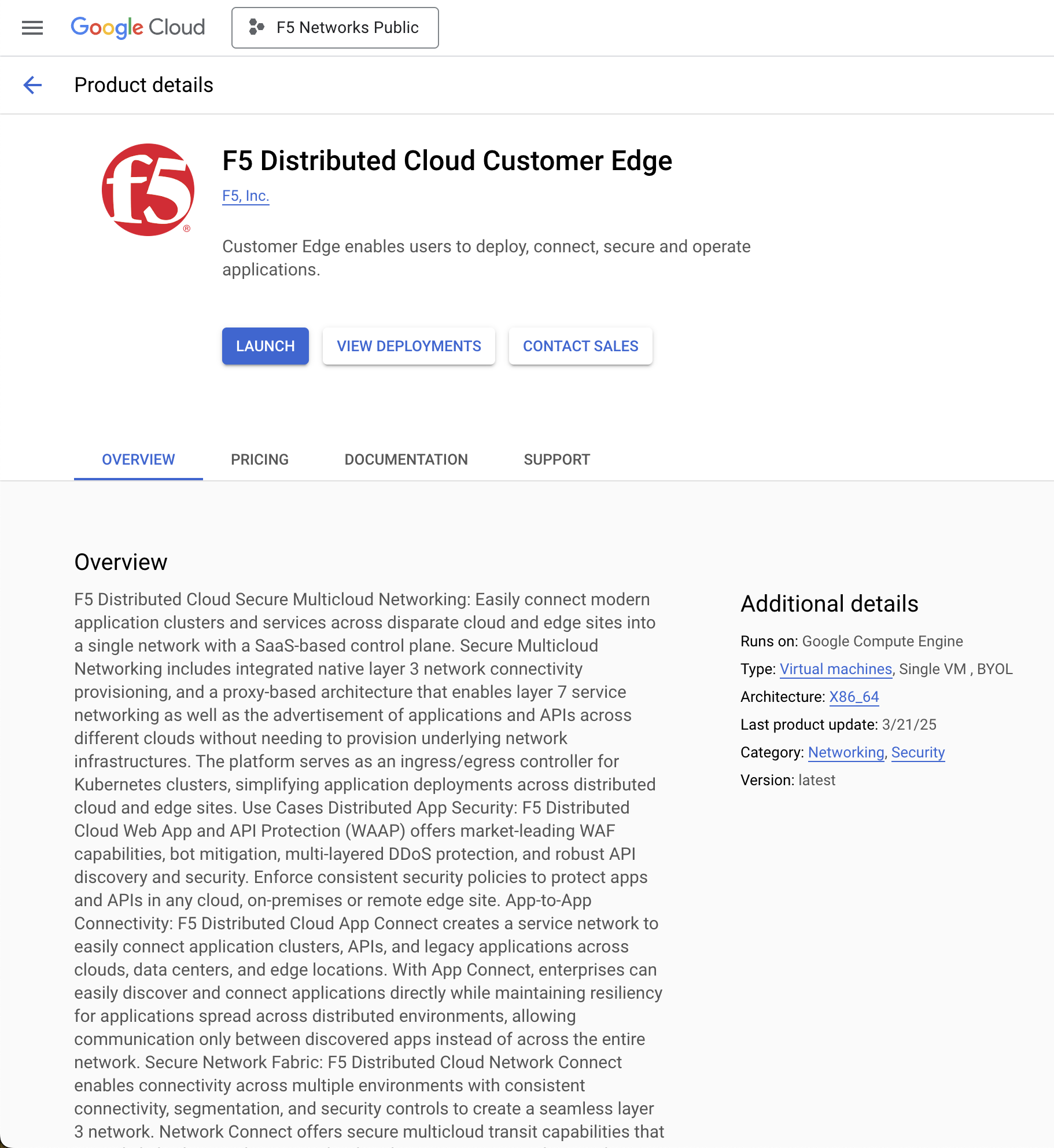
Figure: Launch Instance from Marketplace Listing
Step 2: Configure new virtual machine.
-
In the Deployment name field, enter a name.
-
Select the Deployment Service Account that is used to create the VM. You can use an existing account or create a new account. If you select an exiting account, use the drop-down menu to select the service account.
-
Select the Zone (the region is implicitly selected based on the zone).
-
Under Machine type, select the following for the node VM instance size:
- Series
- Machine type
Note: This procedure uses the default n2-standard-8 as an example for the CE node VM size. To find your right size and requirements, refer to the Customer Edge Site Sizing Reference guide.
-
Update the boot disk option storage amount if required. The boot disk size is in GB and is set to 80 GB by default.
-
Under Network interfaces, expand the default interface and configure it as the SLO interface of the node VM with the following:
- Select the SLO VPC network.
- Select the SLO subnetwork.
- For the External IP, select the previously created external IP address for the SLO interface.
- Click Done.
-
Click Add a network interface to configure the SLI for the node VM with the following:
- Select the SLI VPC network.
- Select the SLI subnetwork.
- For the External IP, select None.
-
Under Network Tags, click Add item and add the network tags to match the tags for the firewall rules.
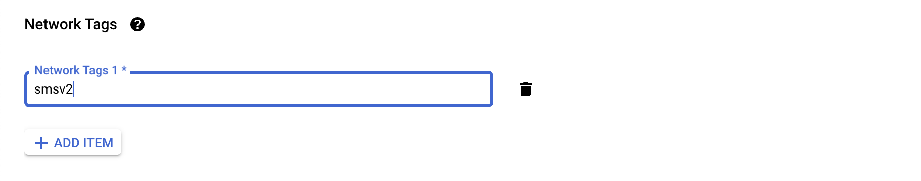
Figure: Configure Network Tags
- Under Metadata, paste the node token generated previously in section Generate Node Token.

Figure: Configure Metadata
- Under SSH Keys, click Add item and paste your SSH public key in the text box. This is used for SSH log in to the node for debugging, if required.
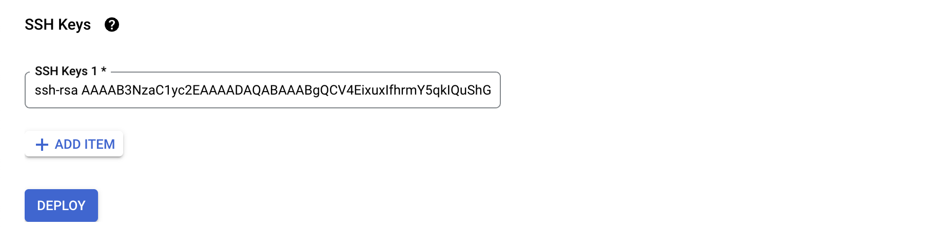
Figure: Configure SSH
- Click Deploy to create the VM.
Terraform Example for GCP VM Instance Creation Using GCP Marketplace Image
You have the option to automate the deployment of the latest available GCP Marketplace image using the GCP-provided Terraform.
- Fetch the latest image matching the f5xc-ce-crt- prefix.
data "google_compute_image" "f5_ce_image" {  project = "f5-7626-networks-public"
filter = "name ~ 'f5xc-ce-crt-'" most_recent = true}- Create a GCP VM instance using the fetched image.
resource "google_compute_instance" "f5_ce_vm" {  name         = "f5-ce-instance"
  boot_disk {    initialize_params {      image = data.google_compute_image.f5_ce_image.self_link    }  } # … Rest of the configuration}
Launch Node VM Instance from Downloaded File
If you want to create VM node using a downloaded file, follow the instructions below.
Important: Starting March 2026 release of F5 Distributed Cloud, the Actions > Download Image and Actions > Copy Image Name options were removed for GCP provider from F5 Distributed Cloud Console. If you need to download the latest image, use this download link.
Step 1: Download image.
-
Download the latest image. The file downloads as a
f5xc-ce-crt-<version>.tar.gzfile onto your local machine. -
Ensure you validate the integrity of the file using the MD5 checksum c9e3886a6210326ed15a64133e4c9c5d.
Step 2: Create storage bucket in GCP Console.
-
In the Storage Bucket service in the GCP Console, click Create. Enter a name for your storage bucket. Configure other options as desired. Afterwards, click Create.
-
In your newly created bucket, click Upload > Upload files. Upload the downloaded image file.
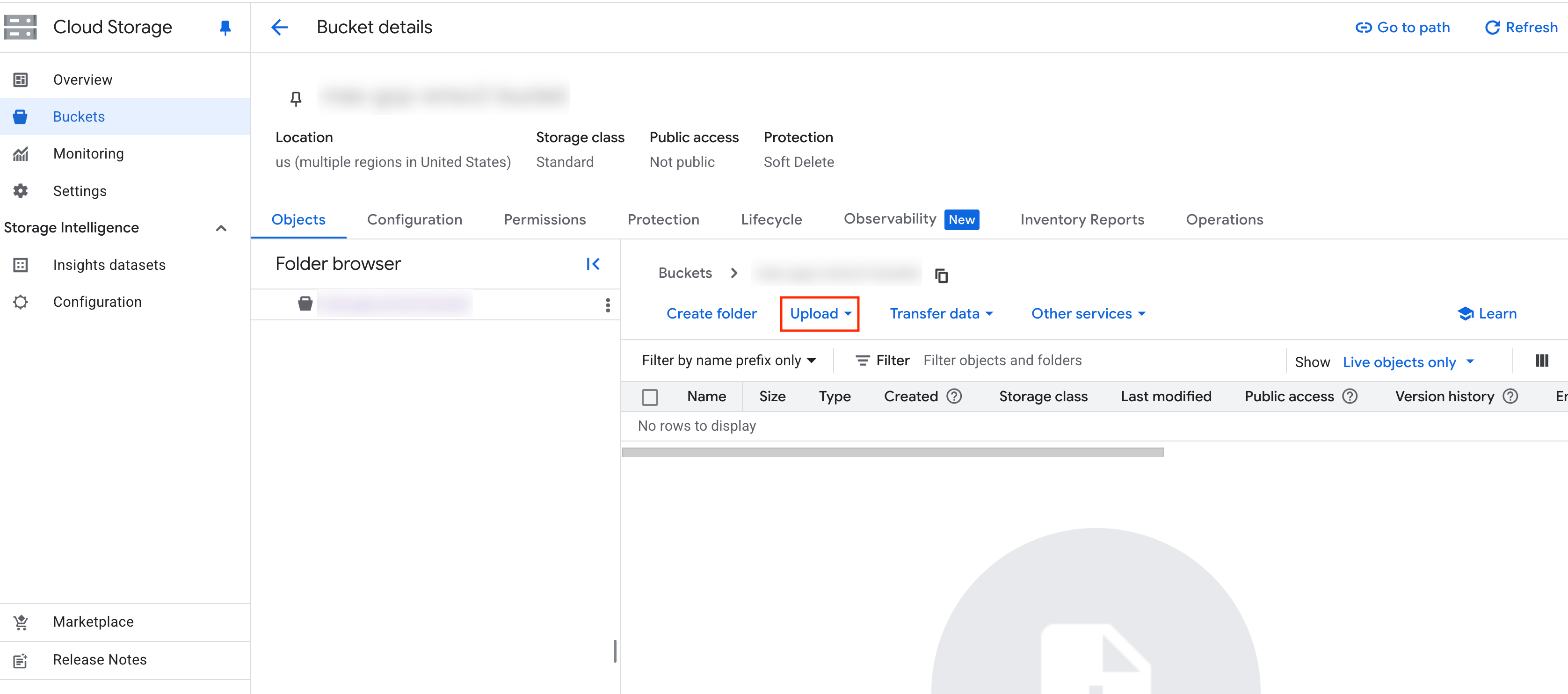
Figure: Upload Node Image
Step 3: Create image in GCP Console.
-
Navigate to Compute Engine > Storage > Images.
-
Click Create Image.
-
Enter a name for the image and select the Source as Cloud Storage File.
-
Click Browse to select the image file from Storage Bucket.
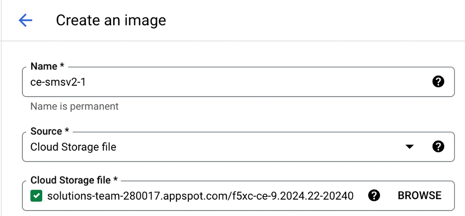
Figure: Create Node Image
-
Leave the rest of the options in their default configurations.
-
Click Create.
Step 4: Create VM from image.
-
Navigate to the image previously created.
-
Click Create instance.
Step 5: Configure VM name, region, and storage.
-
Enter a name for the VM.
-
Select the region and where you want to deploy the node.
-
Select the VM machine type. This procedure uses the default n2-standard-8 as an example for the CE VM size. To find your right size and requirements, refer to the Customer Edge Site Sizing Reference guide.
-
In OS and storage, click Change and make the following changes:
- Set the Boot disk type to Standard persistent disk.
- Set the Size (GB) to 80 GB.
-
Click Select.
Step 6: Configure VM networking.
-
In Networking, add network tags to match the tags for the firewall rules.
-
Do not add a hostname. Keep this field empty.
-
Enable IP forwarding.
-
Under Network interfaces expand the default interface and configure it as the SLO interface of the node with the following:
- Select the SLO VPC network.
- Select the SLO subnet.
- Select Ephemeral (Automatic) for the Primary internal IPv4 address.
-
For External IPv4 address, click on the drop-down menu. Click Reserve Static External IP address, provide a name, and then click Reserve.
-
Click Add a network interface to configure the SLI for the node as below:
- Select the SLI VPC network.
- Select the SLI subnet.
- Select Ephemeral (Automatic) for the Primary internal IPv4 address.
- For External IPv4 address, select None.
-
If additional interfaces are required, refer to the section below before proceeding. You cannot add additional interfaces after the VM instance is created.
Step 7: Configure VM security settings.
-
In Security, expand Manage access.
-
Under Add manually generated SSH keys, click Add item and paste your SSH public key in the text box. This is used for SSH log in into the node for debugging, if required.
-
In Advanced, navigate down to the Metadata section.
-
Click Add item and use the following information to add two metadata key-value pairs:
| Key | Value | Notes |
|---|---|---|
| VmDnsSetting | ZonePreferred | Zonal DNS mitigates the risk of cross-regional outages and improves the overall reliability of the VM. |
| user-data | Copy and paste the cloud-init format along with node token information from above. | This allows the node token to be used for registration of the node. |
#cloud-configwrite_files: - path: /etc/vpm/user_data permissions: 644 owner: root content: | token: <node-token>- Click Create to create the VM.
Verify CE Site Registration
After you deploy your nodes, they automatically register as a CE Site in Distributed Cloud Console. The registration process is not instantaneous. In Console, the status changes from Waiting for Registration to Provisioning to Online. Wait a few minutes for the registration process to begin after completing the preceding sections.
-
In Distributed Cloud Console, navigate to Multi-Cloud Network Connect > Overview > Infrastructure > Sites.
-
Select your CE Site. The Dashboard tab should clearly show that the CE Site has registered successfully with the System Health of 100% as well as Data Plane/Control Plane both Up.
Note: For more information on the CE Site registration process, see the Customer Edge Registration and Upgrade Reference guide.
Manage Network Interfaces (Optional)
After your CE Site registers successfully, you might want to add additional network interfaces to meet your requirements. Ensure that you connect another network interface to the node VM.
Important: Adding a new network interface causes the data plane services to restart. Therefore, F5 strongly recommends that you perform this operation during maintenance windows. As data plane services restart, traffic drops are expected, as well as tunnels going down.
All nodes in a given CE site should have the same number of network interfaces attached.
Each node in the CE site should have interfaces with the same VRFs assigned. For example: If a CE site has three nodes, each node having two interfaces - the first interface on each node is auto-configured to be in the SLO VRF (to connect to F5 Distributed Cloud). If the second interface on node-1 is in the SLI VRF, then the second interface on node-2 and node-3 should also be in the SLI VRF.
When adding interfaces, it is important to make sure that the interfaces are added to each node in the cluster. Nodes with non-homogenous interfaces within a CE Site might cause issues. Therefore, each node in a given CE Site should have the same number of interfaces placed in the same VRFs.
After you configure the SLO interface with a static IP address, DHCP will still be displayed in the Console. However, your static IP configuration is well taken into account. Also, remember that you cannot modify SLO parameters once the node is registered and deployed.
Add New Interface
To add extra interfaces to an instance on GCP, ensure the following conditions are met:
- Additional interfaces can be applied to a node VM only while initially creating it.
- GCP does not support adding new interfaces after the node VM is created.
- Each interface must connect to a different VPC network.
Important: The IP address ranges of the two interfaces on the same instance must not overlap.
-
Click Add a network interface to configure an additional SLI interface for the node VM. Use the following parameters:
- Select the additional VPC network.
- Select the additional subnetwork.
- Select Ephemeral for the Primary internal IPv4 address.
- For External IP, select None.
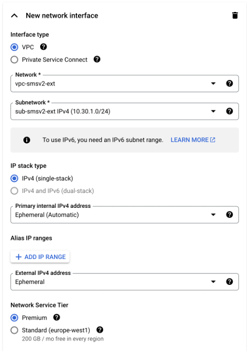
Figure: Add SLI Interface
Modify Interface Attributes
Step 1: Navigate to your CE Site.
-
Power down the node VM prior to modifying any existing interfaces.
-
In Distributed Cloud Console, navigate to your CE Site.
-
Click Manage Configuration > Edit Configuration.
Step 2: Modify node VM interface.
-
Under the Nodes subsection, click the pencil icon under Actions to edit.
-
Choose the interface to modify.
-
Change the settings as required. In this example, the interface is being placed in the prod-segment. Therefore, the setting from the original Site Local Inside (Local VRF) to Segment was changed. Then the required segment is selected.
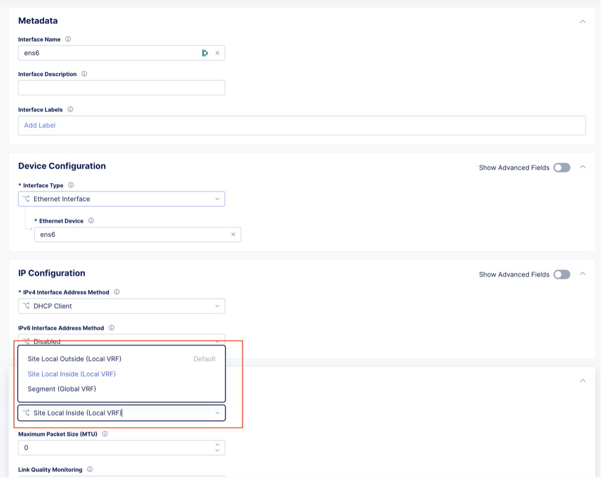
Figure: Edit Interface
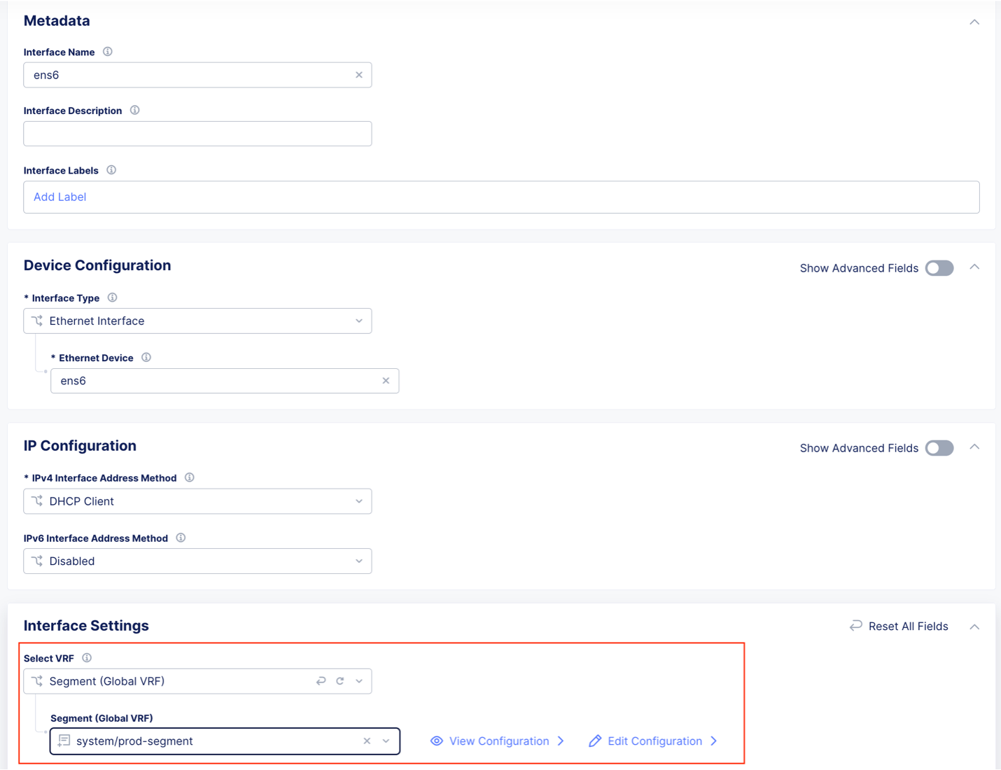
Figure: Edit Interface
Step 3: Save changes.
-
Click Save Secure Mesh Site.
-
Power back up the node VM.
Day 2 Operations
- To monitor your Site, see the Monitor Site guide.
- To manage your Site software and OS updates, see the Manage Site guide.
- For troubleshooting issues, see the Troubleshooting Guide for Secure Mesh Site v2 Deployment guide. It provides step-by-step instructions to debug and resolve the issues that may arise due to registration and provisioning errors.
- For the latest on Distributed Cloud Services releases, see Changelogs.
- To view the various types of events generated, see the Events Reference guide.
Related Guides
To create a load balancer on the CE Site, see the HTTP Load Balancer or the TCP Load Balancer guides.
Concepts
On this page:
- Objective
- Planning
- General Prerequisites
- IAM Required Roles
- Configuration Overview
- Procedure
- Create Site Object
- Create VPC Networks and Subnets
- Configure Firewall Rules
- Reserve External IP Address
- Generate Node Token
- Create GCP Virtual Machine
- Launch Node VM Instance from GCP Marketplace
- Terraform Example for GCP VM Instance Creation Using GCP Marketplace Image
- Launch Node VM Instance from Downloaded File
- Verify CE Site Registration
- Manage Network Interfaces (Optional)
- Add New Interface
- Modify Interface Attributes
- Day 2 Operations
- Related Guides
- Concepts