Customer Edge Deployment Models for Resiliency
Objective
This guide provides a technical framework to help architects and operations teams determine when to deploy F5 Distributed Cloud Customer Edge (CE) nodes as a cluster or as independent multi-sites to achieve high availability (HA) and resiliency in a single location. It compares how each model behaves across failure domains, tunnel architecture, scaling characteristics, operational workflows, and feature support. The goal is to guide the selection of the most appropriate CE deployment approach, based on application behavior, resiliency targets, and operational constraints.
This guide assumes that you are familiar with basic networking concepts like routing protocols, DNS, and data center network architecture. It also assumes that you are aware of various F5 Distributed Cloud Services concepts such as load balancing, BGP configuration, sites, Site Mesh Group and virtual sites, and Site Local Inside (SLI) and Site Local Outside (SLO) interfaces.
Introduction
The F5 Distributed Cloud Services platform enables enterprises to extend advanced application delivery, security, and networking services closer to end-users through CE nodes deployed at data centers, branch offices, or cloud edges. A critical design decision in deploying these CE nodes revolves around where one needs a high availability (HA) architecture and where redundancy is required. F5 Distributed Cloud Services primarily offers two deployment models to achieve this and scale: clusters and independent multi-sites:
- Clusters: Where nodes operate together within a single site.
- Independent multi-sites: Independent CE sites within a single location or across physical locations.
Deployment Model Overview
HA with F5 Distributed Cloud Services CE deployments is designed to ensure continuity of application delivery during node failures, network interruptions, or planned operational activities, like upgrades. While both cluster-based and independent multi-sites deployments aim to maintain service resilience, the strategies for handling traffic distribution, node isolation, and failover differs.
Clusters - Local and Tightly Coupled
A cluster deployment requires at least three nodes for HA, which could be control nodes and worker nodes that are added later. Here each site connects via tunnels to two geographically-distinct REs for redundant connection to the F5 global network. All the nodes within a cluster are programmed to work as one single entity. If one CE node fails in the cluster, another immediately takes over without significant disruption.
Cluster deployments do not support mixing nodes of different capacities, which may restrict flexibility in some environments. All nodes in a cluster must be of the same size to ensure uniform distribution of traffic and balanced resource utilization. The cluster deployment acts as a single routing and service entity, simplifying management and routing configurations.
Common use cases include:
-
High availability for application delivery services: A CE cluster deployed within the same site allows applications to remain available if one CE node fails due to hardware issues, OS crashes, or maintenance events. Traffic continues to flow through the remaining nodes without any significant service interruption.
-
Load distribution across CE nodes: When multiple CE nodes are deployed as a cluster in the same location, application traffic can be distributed across nodes. This helps with avoiding overloading a single node and provides good performance in case of peak load.
-
Horizontal scaling for application growth: You can add more (worker) nodes in case there is an application’s growth in terms of performance required for traffic processing at L7 for private load balancer use cases.
Independent Sites - Distributed and Loosely Coupled
In contrast, independent site deployments where setup can start with at least of two single node sites enabling minimal yet resilient architecture, is a logical construct, where application availability can span across CE nodes within the same physical location or co-located (or handled at across different regions or data centers that are geographically distributed). Here each site operates independently, establishing its own routing, tunnels, and service integrations. This loose coupling allows sites to support nodes of different sizes, making it easier to tailor hardware resources to local requirements.
Co-located: A locally used site groups multiple CE sites within the same physical location. In this model, the sites are still independent at the data plane but grouping them allows consistent configuration (leveraging virtual site construct), policy enforcement, and traffic segmentation within the same data center or campus.
Geographically distributed: This is a logical construct that groups multiple independent CE sites that are designed to span across geographic locations, data centers, or cloud regions, making applications available in all these locations. This approach is used when the origin server is not directly available and resides in a different location and all other source locations sites form a Site Mesh Group (SMG) to connect the site where the origin server is present as this helps uniform policy enforcement and route advertisements with help of a virtual site construct.
Common use cases include:
-
True active/active HA and higher throughput: REs distribute traffic evenly across all CE Sites, resulting in higher aggregate ingress throughput.
-
Staged migration: Running a new CE Site alongside an existing one during phased cutovers.
-
Controlled operations and upgrades: An administrator can remove a CE Site from the virtual site (by removing its label) to perform upgrades, while traffic is seamlessly re-routed to the remaining operational nodes. As maintenance is performed on a site-by-site basis, it reduces the risk of a full-site outage during updates.
Key Differentiators
This section compares the two deployment models, cluster and independent multi-site (with optional virtual site grouping), across cost, connectivity, scaling, availability, management, operations, and feature support.
Initial Cost
Cluster deployment: Requires a minimum of three CE nodes to achieve HA. The first three nodes become the control nodes. The additional nodes become worker nodes. This raises the entry capital expense cost to achieve HA.
Independent multi-site deployment: Resiliency can start with two single‑node CE sites, so the minimum cost to achieve redundancy is typically lower than with clusters.
RE Connectivity
For cluster deployments:
-
The site forms two tunnels total to the F5 REs: one to a designated primary RE and one to a secondary RE in the selected region. These tunnels are established from any two of the three control nodes, simplifying the design within a single data center for public and private application use cases.
-
For public applications, as shown in the diagram below, the ingress throughput is effectively bounded by these two site-level tunnels. For private applications, this is not a constraint because data traffic can land directly on CE nodes in the site.
For independent multi-site deployments:
- Each CE site establishes its own two tunnels to distinct REs in the chosen region, allowing granular connectivity and aggregate ingress throughput to scale as more sites are added.
For both models:
- Either of the deployments models support offline survivability, wherein when the tunnels to REs are down, the CE nodes can continue processing private application data traffic locally (management and control access via the Console are unavailable). If enabled, a CE Site can continue to process data traffic for up to seven days without RE connectivity and can persist across reboots during that period.
Scaling
For cluster deployments:
- No hard limit on the total CE nodes per cluster.
- Exactly three control nodes maximum. All additional nodes are worker nodes.
- Homogeneous hardware is required. All CE nodes in a cluster must have the same size and type (for example, all medium or all large).
- Public application access (via tunnels): As shown in the diagram below for the workflow, traffic lands on one of the control nodes (which hold the tunnels) and may be forwarded to an RE-selected worker node via intra-cluster connectivity.
- Private application access: Within the location (or across an SMG), traffic reaches the origin server via a CE site chosen by BGP or an external network load balancer (NLB).
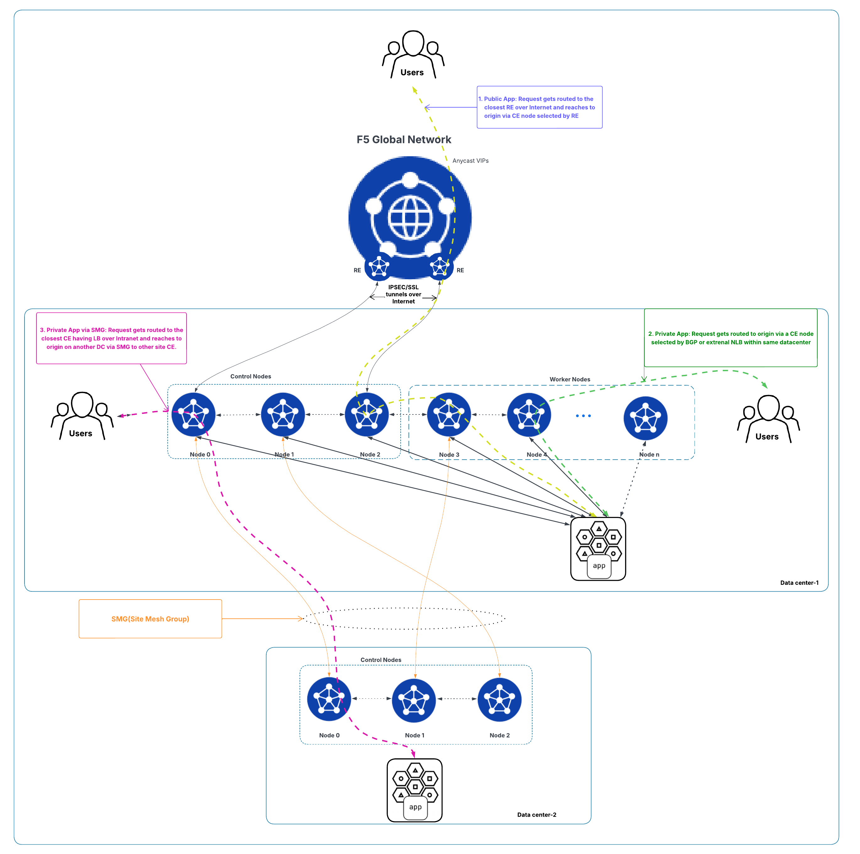
Figure: Scaling and Traffic Flow with Cluster Deployment
- Worker nodes are most beneficial for private application scenarios that require high L7 processing (for example, security or service policies). For public applications, scaling considers each CE’s requests per second (RPS) capability.
- The SMG between locations (cluster to cluster): The number of site-to-site tunnels is determined by the cluster that has the fewer nodes. Tunnels can form to control or worker nodes. As shown in the figure above, the "Data center-2" is a three-node cluster. Therefore, the number of tunnels for the SMG that will be formed between two locations is three:
- "Data center-2" Node 0 (control) to "Data center-1"’s Node 0 (control)
- "Data center-2" Node 1 (control) to "Data center-1"’s Node 3 (worker)
- "Data center-2" Node 2 (control) to "Data center-1"’s Node 1 (control)
For independent multi-site deployments:
- Any number of CE sites can be used to achieve resiliency and scale.
- Heterogeneous hardware is supported. You can mix different CE sizes across sites.
- Public application access (via tunnels): Traffic lands on any CE site (each has two tunnels) selected by the RE and reach the origin server accordingly.
- Private application access: Traffic reaches the origin server via a CE selected by BGP, or an external NLB (same mechanisms as cluster).
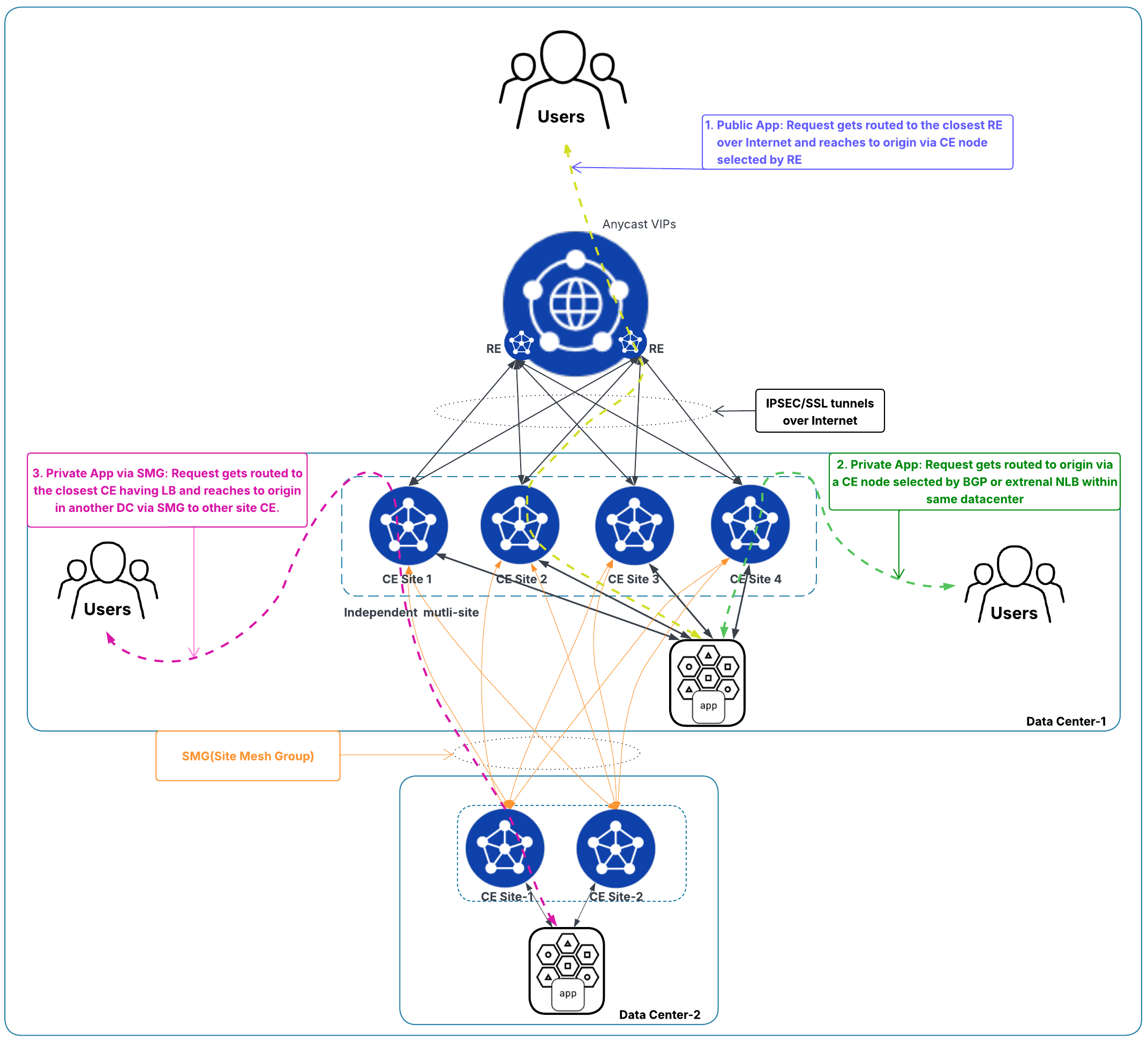
Figure: Scaling and Traffic Flow with Independent Multi-site Deployments
- SMG between locations (independent to independent): Forms a full mesh between sites. Example: As shown in the diagram above, if "Data center 2" has two CE sites and "Data center 1" has four CE sites, the inter-location mesh forms eight tunnels total (each of the two sites in "Data center 2" forms four tunnels to the four sites in "Data center 1").
High Availability
For cluster deployments:
- Data traffic remains unaffected as long as at least two of the three control nodes are healthy. If two nodes fail, data traffic will be disrupted.
- If a tunnel on a control node goes down but the node remains healthy, the traffic continues with no tunnel failover to another control node. The affected node keeps attempting to re-establish the tunnel. See figure below for example.
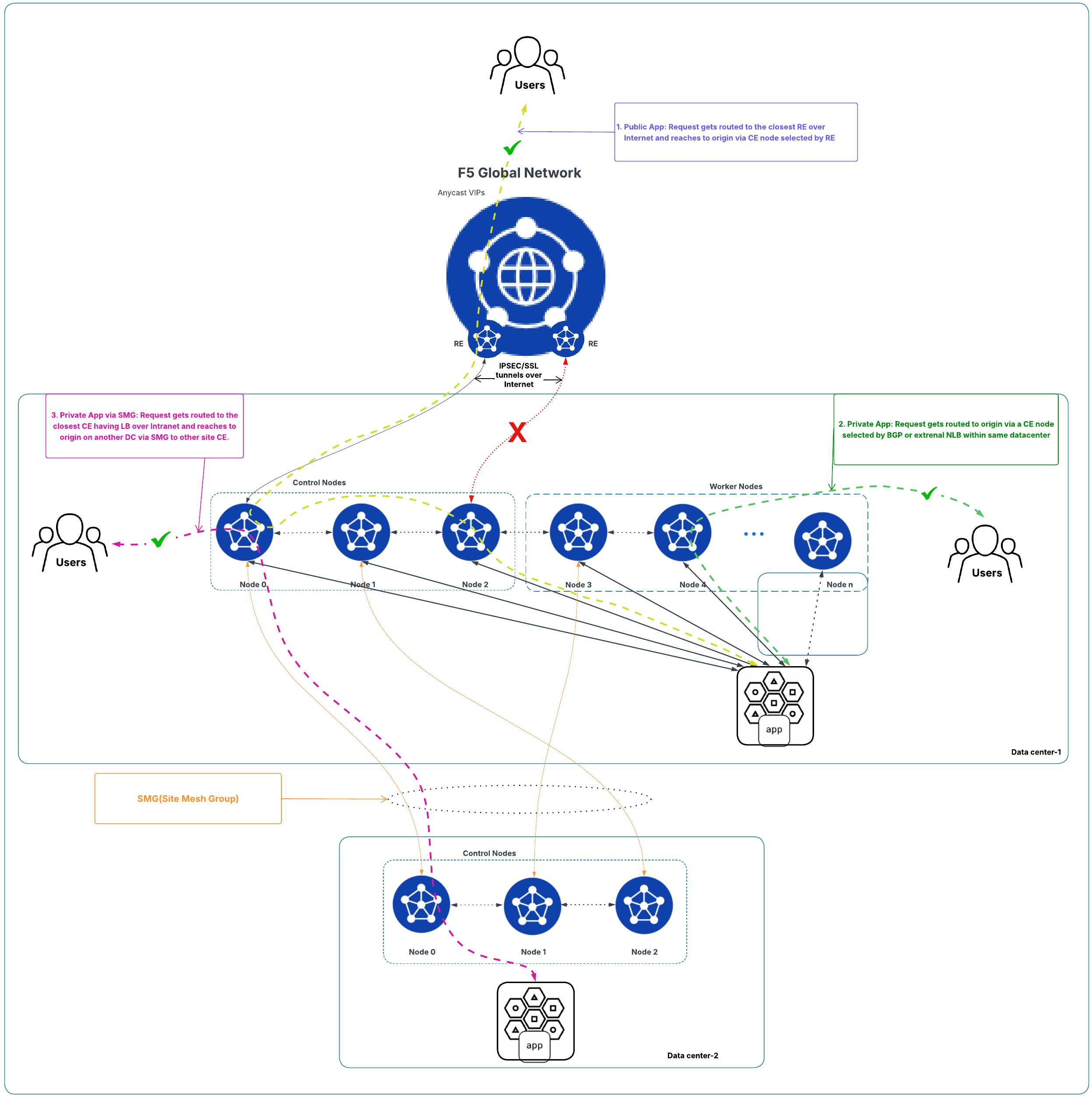
Figure: Traffic Flow State for Cluster Deployment with One Tunnel Down
- If a control node fails, the tunnel to its RE is re-established via the third control node, keeping control, management, and data traffic unaffected. See figure below for example.
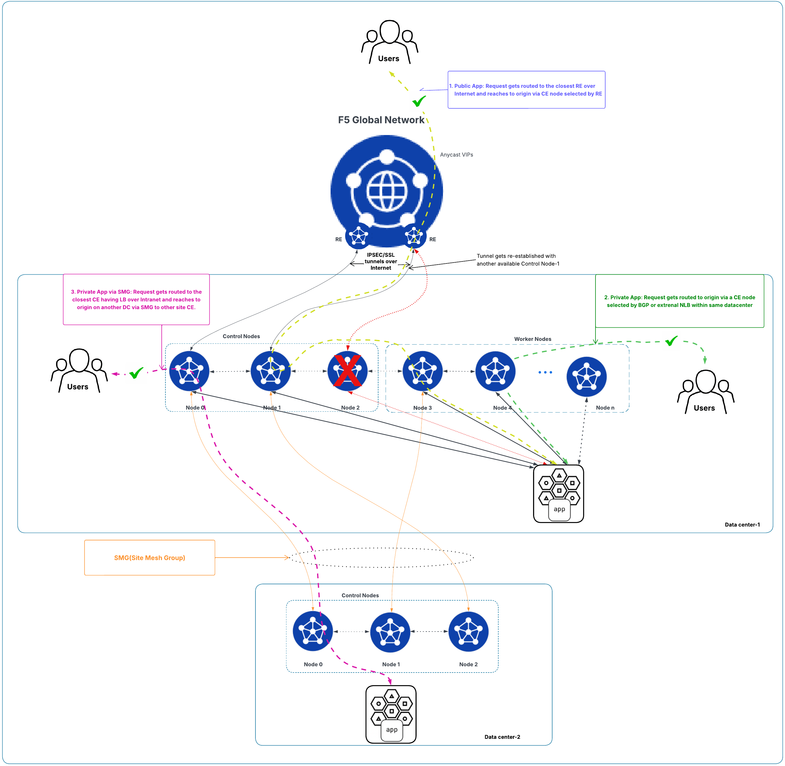
Figure: Traffic Flow State for Cluster Deployment with One Control Node Down
For independent multi-site deployments:
- Redundancy is per site: Any number of sites may fail, and traffic remains uninterrupted as long as at least one site remains healthy and has capacity for the aggregate requests. See figure below for example.
- Because each site has two tunnels, if one tunnel fails at a site, data and control traffic continue via the other remaining tunnel while the site attempts to re-establish the failed one.
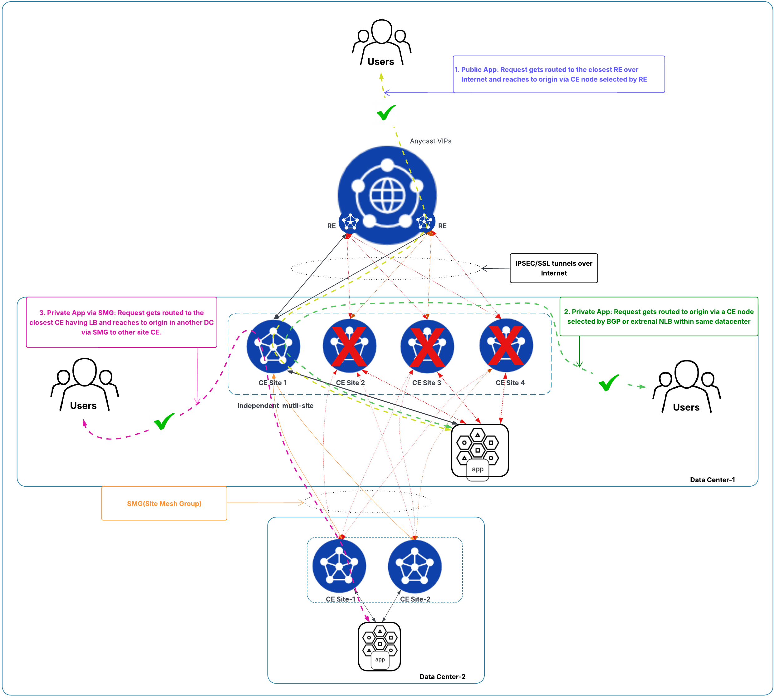
Figure: Traffic Flow State with Independent Multi-Site Deployments with Only One Node Available
Management
For cluster deployments:
- Centralized management via F5 Distributed Cloud Console: A simpler experience for intra-site HA (push configuration once to the cluster/site).
- Unified views and tools for routing tables, troubleshooting (for example, tcpdump), and single pane visibility into overall and per-node health (health scores and alerts).
For independent multi-site deployments:
- Per-site management for many settings (for example, static routing, DNS, log streaming, NTP, node local services, admin credentials, and troubleshooting tools).
- Using a virtual site (logical grouping) can simplify configuration distribution across multiple independent sites for features such as load balancers, SMG, BGP, origin discovery, and service discovery.
- Segmentation and BGP routing policies and External Connectors must be configured per site.
Operations
For cluster deployments:
- One-click upgrades for the cluster. All nodes in the cluster are upgraded together.
- Minimal service disruption of a few seconds (about 10-15 seconds) during node upgrade.
- No control over upgrade sequencing (you cannot choose which node, control versus worker, upgrades first).
- Centralized operations for static routing, DNS, log streaming, NTP, node local services, admin credentials, and built in tools (for example, routing table views and tcpdump).
- Despite being a cluster, you still have per-node health visibility (infrastructure, metrics, routes, alerts, and more).
For independent multi-site deployments:
- Site-by-site upgrades: More operational steps, but you gain fine-grained control over the upgrade order to preserve application availability.
- Per site configuration for static routing, DNS, log streaming, NTP, node local services, and admin credentials.
- Per site use of diagnostic tools (routing tables and tcpdump).
Feature Exceptions
-
SNAT for origin servers is supported in cluster deployments. SNAT pools are assigned per node and managed within the site boundary, enabling predictable source IP behavior even when flows rehash due to ECMP or network conditions. To learn more, see the SNAT Pool Configuration in Origin Pool reference guide.
-
Within independent sites, the SNAT for origin servers must be configured separately on each site. This contrasts with a cluster deployment, where the SNAT IP address pool is automatically distributed across all nodes within the cluster.
-
Within independent sites, the SNAT for origin servers must be configured separately on each site. This contrasts with a cluster deployment, where the SNAT IP address pool is automatically distributed across all nodes within the cluster.
-
VRRP are not available with an independent multi-site.
Operational Scenarios and Which Model to Choose
Choose cluster deployment (local HA) when you want to group multiple CE nodes within the same physical site to operate as a single logical unit for HA and load distribution. Configuration and state are shared, enabling seamless failover on node loss.
The key advantages include:
- Simplified management: Single control plane for all nodes within the cluster, reducing operational overhead for intra-site HA.
- Shared capacity: All nodes contribute to one resource pool for efficient hardware utilization.
- Deterministic source IP address control: SNAT for origin servers (with per node SNAT pools) is supported within the cluster/site boundary.
- Local failover: Traffic continues as long as two control nodes remain healthy. Tunnels are re-established automatically on control node loss.
The example use cases include:
- Processing heavy private applications (L7 security/policy) where worker nodes provide scalable data plane capacity.
- Branch offices or data centers where intra-site HA and operational simplicity are prioritized.
Choose independent sites when you want to deploy independent multi-site and optionally group them with a virtual site construct to achieve consistent configuration at scale, while retaining per-site control over upgrades and routing. This model also scales ingress throughput for public applications because each site contributes two tunnels.
The key advantages include:
- Higher aggregate throughput: Each additional site adds two RE tunnels, increasing total ingress capacity for public applications.
- Upgrade control: Perform site-by-site upgrades to maintain availability during maintenance windows.
- Configuration consistency at scale: Virtual site construct enables uniform policies/configurations (for example, load balancers, SMG, BGP, origin/service discovery) across many sites.
- Resiliency across sites: Traffic remains available as long as one site is healthy with sufficient capacity, even if multiple sites fail.
The example use cases include:
- Two availability zones (or multi-building) deployments within the same location, where independent sites provide high throughput and failure domain isolation.
- Applications with very high ingress bandwidth or tunnel fan out requirements beyond a cluster’s two tunnel limit for public traffic.
Deployment Model Summary
F5 Distributed Cloud Services provide two complementary models for delivering resilient, high performance edge services:
-
Cluster deployment is optimal for local HA within a single site. It delivers fast intra-site failover with a minimal service disruption of few seconds, unified operations and management, shared capacity, and deterministic SNAT for origins, but public application ingress is constrained by the two site-level tunnels, and upgrade sequencing cannot be controlled.
-
Independent multi-site deployment excels when you need throughput that scales with the number of sites, per site upgrade control, and flexible hardware choices. However, you will have to manage more per-site operations. Using a virtual site construct streamlines configuration consistency across many sites. However, seamless distribution of SNAT pool (for origins) and VRRP are not supported in the independent multi-site deployment. If you need VRRP support for your VIPs or gateways, the only option to achieve this is via a cluster deployment.
Selecting the right model, or a combination, should weigh fault domain isolation, throughput targets, feature requirements (for example, SNAT/VRRP), operational model (centralized versus per site), and the failure behaviors you want during upgrades and tunnel or node loss. Offline survivability settings further ensure that private application traffic can continue locally for extended periods when RE connectivity is unavailable.
CE Deployment Reference Architecture
Refer to the F5 Distributed Cloud – CE High Availability Options: A Comparative Exploration article that provides guidance on deploying resilient CE sites for robust application delivery. The article outlines multiple high availability strategies for directing traffic across CE nodes, including Layer 3 ECMP routing (static or BGP), Layer 2 redundancy with VRRP/GARP, external proxy load balancing, and DNS load balancing, each with specific pros, cons, and use cases. For each method, the article discusses operational considerations such as external network configuration requirements, failover behavior, performance implications, and public cloud suitability.
Technical References
- Core Concepts
- Virtual Site
- F5 Distributed Cloud: Virtual Sites - Regional Edge (RE)
- Create Two Node HA Infrastructure for Load Balancing Using Virtual Sites with Customer Edges
- Customer Edge Site High Availability for Application Delivery - Reference Architecture
- Cluster of Nodes
- F5 Distributed Cloud – CE High Availability Options: A Comparative Exploration
- F5 Distributed Cloud - Customer Edge Site - Deployment & Routing Options
On this page:
- Objective
- Introduction
- Deployment Model Overview
- Clusters - Local and Tightly Coupled
- Independent Sites - Distributed and Loosely Coupled
- Key Differentiators
- Initial Cost
- RE Connectivity
- Scaling
- High Availability
- Management
- Operations
- Feature Exceptions
- Operational Scenarios and Which Model to Choose
- Deployment Model Summary
- CE Deployment Reference Architecture
- Technical References