Deploy Edge Infrastructure and Perform App Management
Objective
This quickstart guide provides instructions on how to deploy edge infrastructure and perform application management using F5® Distributed Cloud Console and F5 Distributed Cloud Mesh.
The following image shows the steps to deploy and configure infrastructure and app management:
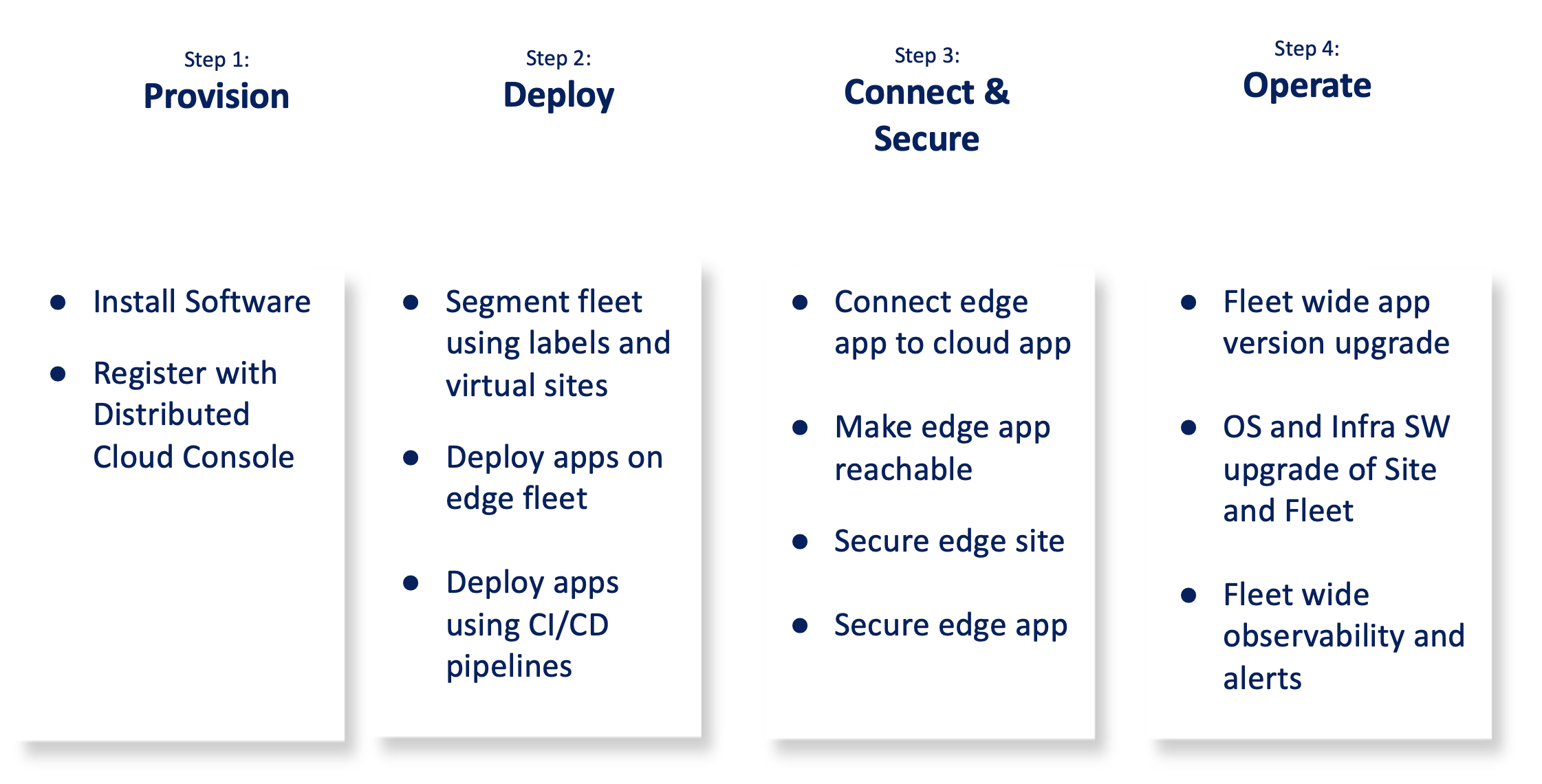
Figure: Overall Procedure
The following image shows the topology for the use case provided in this guide:
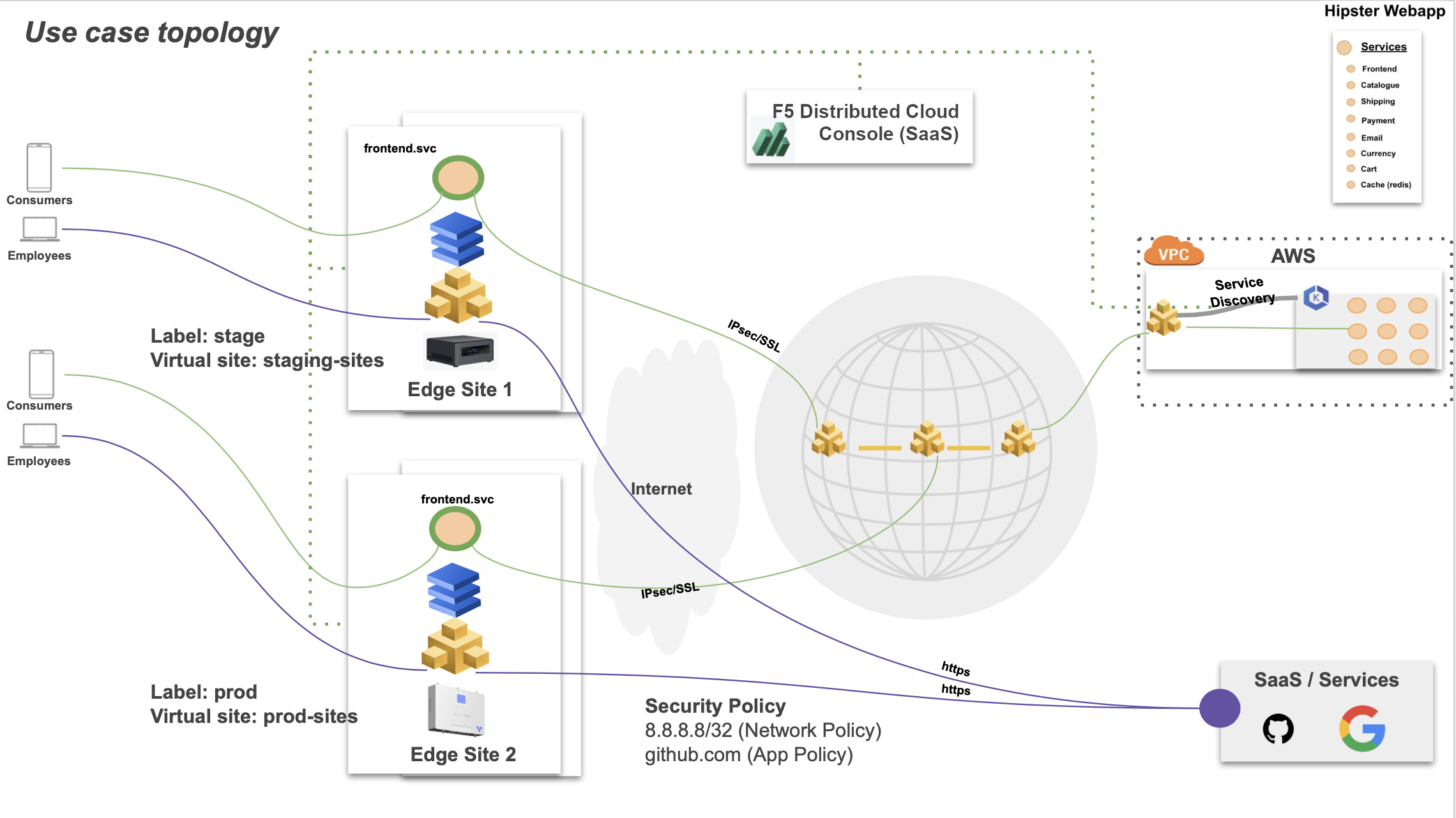
Figure: Sample Topology
Prerequisites
-
Distributed Cloud Console SaaS account. If you do not have an account, see Getting Started with Console.
-
Amazon Web Services (AWS) account. This is required to deploy an F5 Distributed Cloud Console Site.
-
F5 Volterra Industrial Gateway 5008 device.
-
Intel NUC as commodity device with at least 4 vCPUs and 8 GB RAM memory. See the Supported Hardware section.
-
F5 Distributed Cloud Services the vesctl CLI utility. See vesctl for more information.
-
Docker.
-
The balenaEtcher software to flash the F5® Distributed Cloud Service software image on to a USB drive.
-
A secret and policy document for encrypting your certificates and secrets using F5 Distributed Cloud Console Blindfold. See Blindfold for more information.
-
Self-signed or CA-signed certificate for your application domain.
Configuration
The use case provided in this guide deploys sites on the IGW and Intel NUC. The sites are added to a Distributed Cloud fleet and further segmented using labels and virtual sites. After that, apps are deployed to these sites and secure connectivity between the edge apps and cloud apps is configured. The use case also demonstrates how to operate heterogeneous devices by performing software upgrades on the sites and observing the health of them.
The following list outlines the sequence of activities performed for this use case:
-
F5 software is installed on the edge devices and registered on Console.
-
A fleet is created with the required network configurations and fleet label is applied to the site to make it part of the fleet. Also, further sites are further segmented using labels and virtual hosts.
-
Apps are deployed to the edge fleet using the following methods:
- Console
- Kubectl
- CI/CD pipelines
-
The edge and cloud apps are connected using the F5 Distributed Cloud Services virtual host and associated ADC objects. The edge site is secured using network policies. The edge apps are secured using service policies and app firewall.
-
The fleet of edge devices is operated like a single unified logical cloud. As part of that, the application version is upgraded on a sub-segment of edge sites. The operating system upgrade as well as an infrastructure software version upgrade is performed remotely.
-
The heterogeneous set of sites are monitored for health and alerts using F5 Distributed Cloud Platform observability features.
The use case for this document assumes that an application called as Hipster Webapp is deployed with AWS EKS and in an Amazon VPC. Also, a Distributed Cloud Mesh node is deployed in the same VPC with the site name as hipster-webapp-west. The K8s namespace name is hipster.
The application consists of the following services:
- frontend
- cartservice
- productcatalogservice
- currencyservice
- paymentservice
- shippingservice
- emailservice
- checkoutservice
- recommendationservice
- adservice
- cache
Note: Ensure that you keep the Amazon Elastic IP VIPs ready for later use in configuration.
Step 1: Provision
You can use any of the supported hardware devices. However, in case of F5 Volterra IGW or ISV devices, the software is pre-installed, and you can power on, connect through Ethernet or Wi-Fi, and perform registration.
Step 1.1: Download the F5 CE Site node software image.
Download the certified hardware image from the Certified Images page.
Step 1.2: Create site token.
Log into Console and create a site token as per the instructions in the Customer Edge Deployment guides.
Note: You can also use an existing site token. In case you do not have any token, create one for using later for registration.
Step 1.3: Install the software on the device.
-
Install the F5 CE Site node software using the downloaded image on the commodity device as per the instructions in the Create Baremetal Site guide.
-
Log into your device terminal and perform initial configuration. Initial configuration includes setting site token, cluster name, and set default values for rest of the options such as network configuration.
Step 1.4: Perform site registration.
-
Log into Console and select
Managefrom the configuration menu andSite Management>Registrationsin the options. -
Click
Pending Registrationstab and find the registration request for your device. ClickApprove. -
Click
Acceptto confirm.
Note: Check for your device status in the
Other Registrationstab. TheONLINEstatus indicates that the site is provisioned and ready to use.
Step 1.5: Deploy web application and node in the Amazon VPC.
Perform the steps mentioned in the Step 1: Deploy Site chapter to deploy the web application. This step performs automatic site registration.
Step 2: Deploy
This step creates labels and virtual sites to segment the sites and deploys the frontend services of the web application to these sites. The use case covered in this document presents two segments of sites consisting of F5 Volterra IGW and Intel NUC, representing heterogeneous segments. The IGW and the Intel NUC represented as production and staging environments respectively and labeled accordingly. Also, virtual sites are created with these labels to group the sites into staging and production to efficiently deploy the service in case there are many sites in each segment.
Step 2.1: Log into Console, create labels, and add the labels to the edge sites.
Assigning custom labels requires you to create a known key and add the key with custom values to your sites.
Step 2.1.1: Create a known key.
- Change to the
sharednamespace and selectManage>Labels>Known Keys. ClickAdd known keyto open the known key creation form. - Enter a string in the
Label key (Required)field. This example addsenvto indicate the environment as the key. - Click
Add keyto complete creating the key.
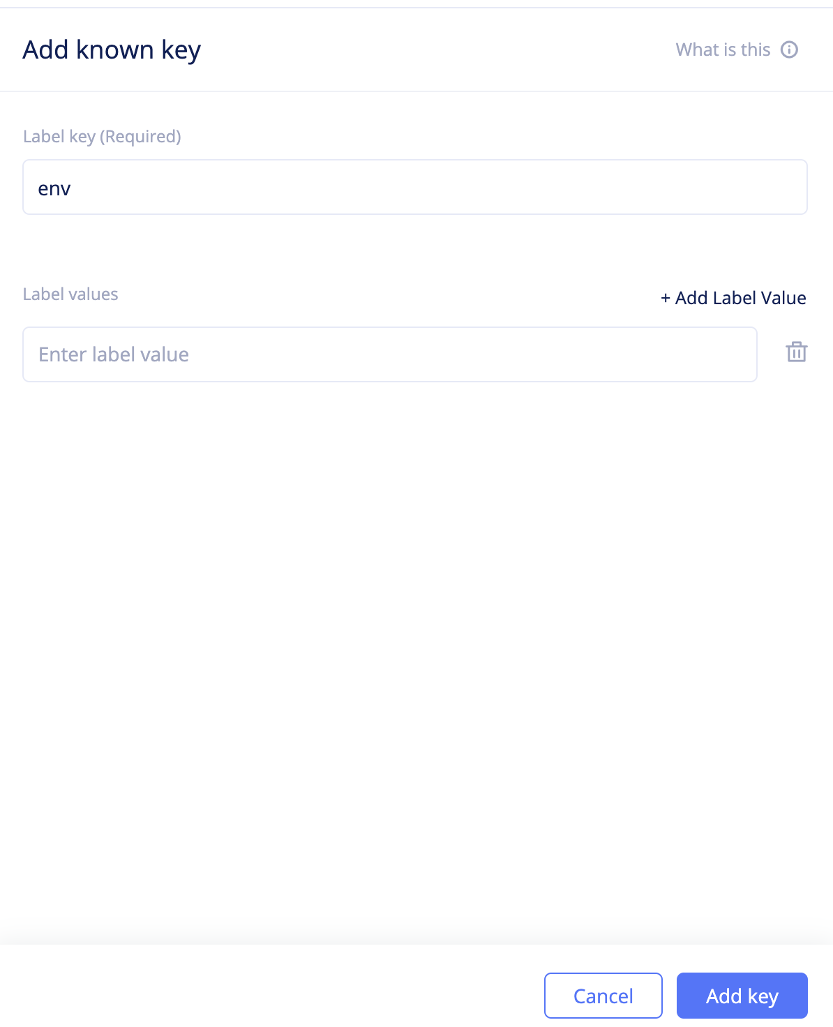
Figure: Create Known Key
Step 2.1.2: Assign the label to the edge sites.
The label is added to the sites in the (key,value) format.
- Change to
systemnamespace and selectSites>Site List. Find your IGW site and click...>Editto open site edit form. - Click on the
Labelsfield and select the key you created from the list of keys displayed. Type a value for the key. This example addsprodas the value representing the production environment. - Click
Save changes.
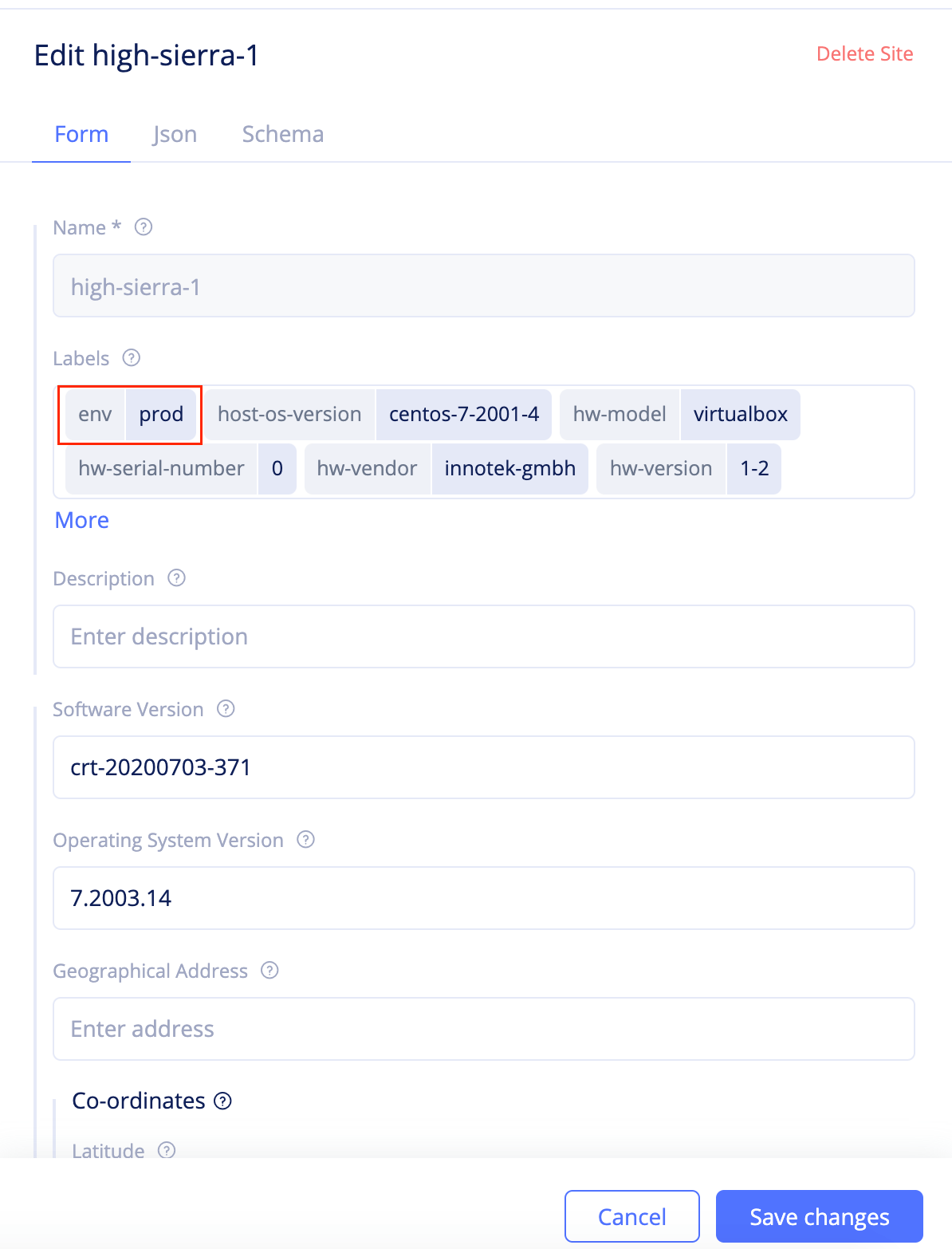
Figure: Assign Label to the Site
- Repeat the above steps to add the
envkey withstagevalue to the Intel NUC site.
Step 2.2: Create virtual sites to segment sites.
Create virtual sites to differentiate segment of sites representing production environment from the segment representing the staging environment.
- Change to the
sharednamespace and navigate toManage>Virtual Sites. ClickAdd virtual site. - Enter a name and select
CEfor theSite Typefield. - Click on the
Selector Expressionfield and selectenvas the key and typeprodas the value. ClickAssign Custom Value 'prod'. - Click
Continueto create the virtual site. This creates the virtual site that groups all sites representing production environment.
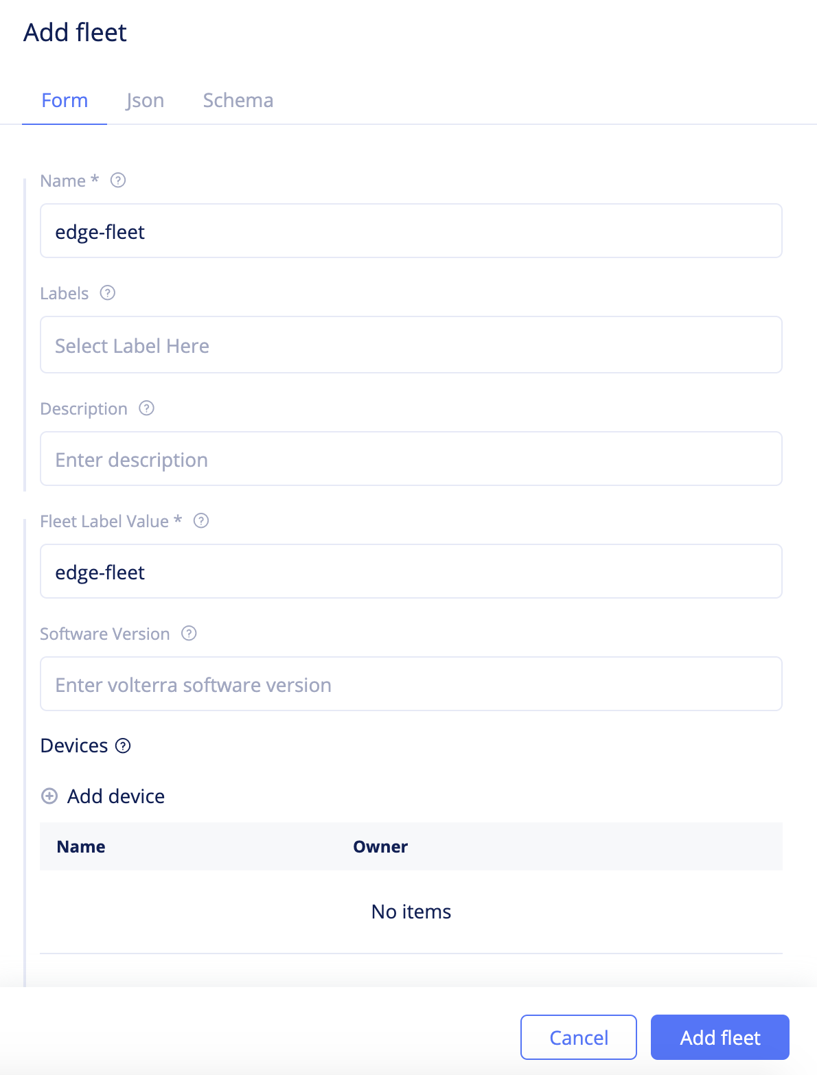
Figure: Fleet Basic Configuration
- Repeat the above steps to create another virtual site with the key
envand valuestagefor theSelector Expressionfield.
Step 2.3: Create a namespace and add vK8s in it.
- Click to open the namespaces dropdown and click
Manage namespaces. - Click
Add namespace, enter a name for your namespace, and clickSave. - Change to the created namespace, navigate to
Applications>Virtual K8s, and clickAdd virtual K8s. - Enter a name and click
Select vsite ref. Select the virtual sites created in the previous step and clickSelect vsite refagain to add the virtual sites to the vK8s. - Click
Add virtual K8sto complete creating the vK8s. - Wait for the vK8s creation to complete and click
...>Kubeconfigto download the vK8s kubeconfig file.
Step 2.4: Deploy the web app and frontend services using the vK8s.
You can deploy using any of the following methods:
Using Console
- Click on the vK8s object to load the vK8s deployments view.
- Click
Add Deploymentand add the manifest of the webapp. ClickSave. The deployments get created.
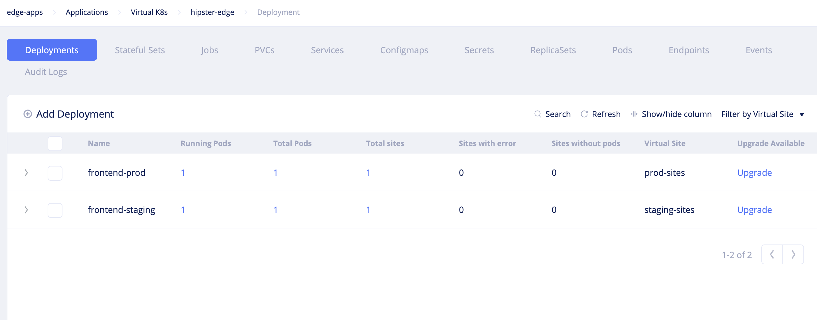
Figure: Deployment Using F5 Distributed Cloud Console
- Open the
Servicesview, clickAdd service, and add the manifest of the frontend service. ClickSave.
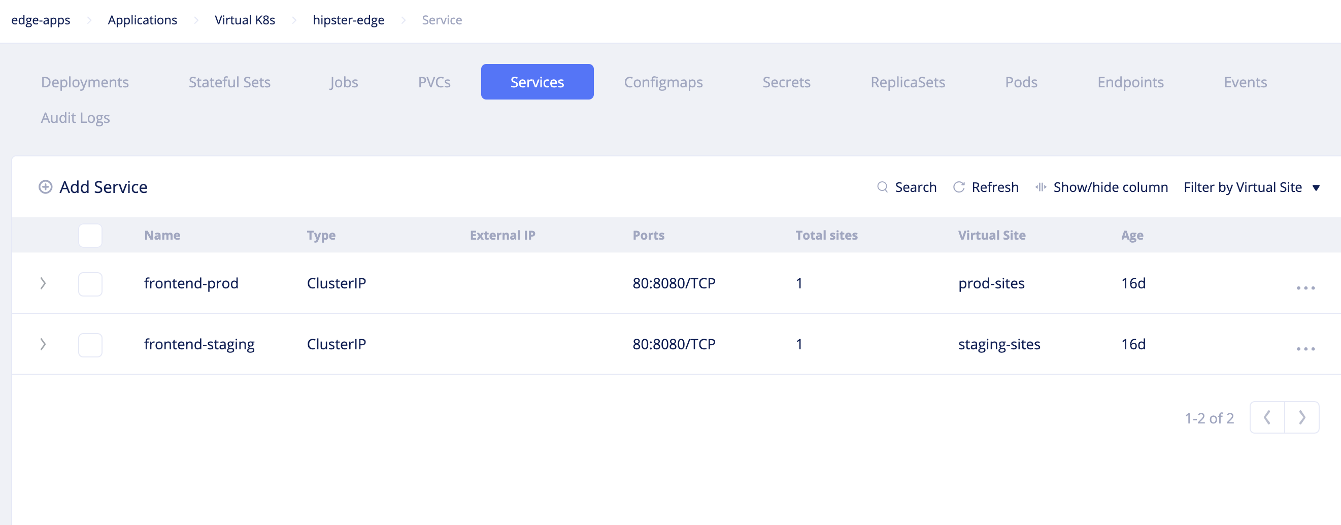
Figure: Services View
- Open the
Podsview and verify that the pods are created and that their status isRunning.
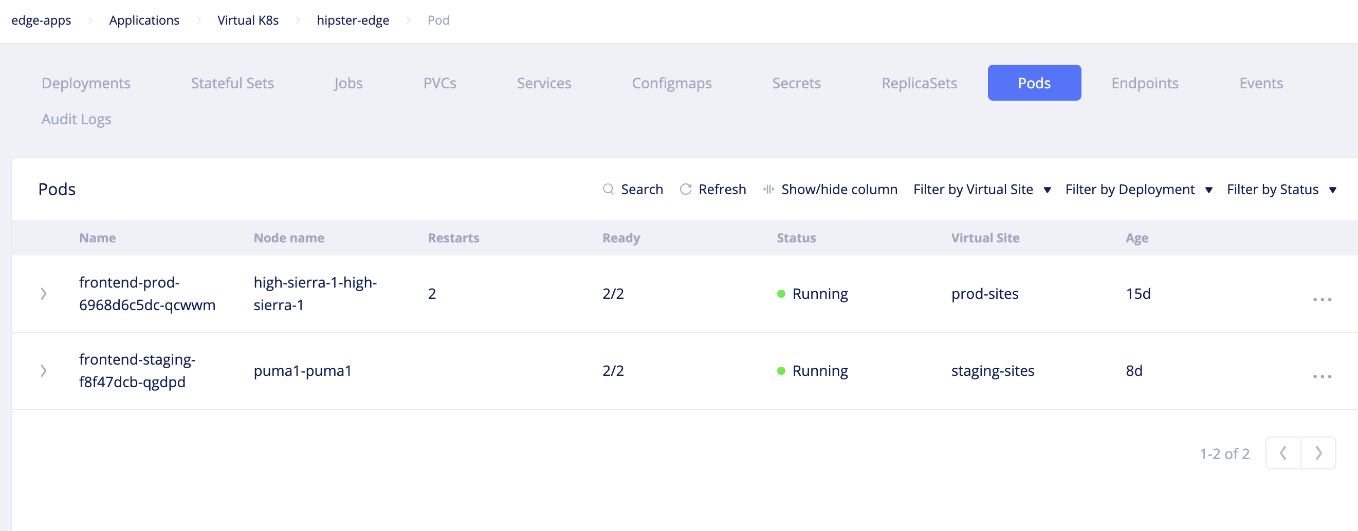
Figure: Pods View
Using Kubectl
- Set the downloaded kubeconfig of the vK8s to the
KUBECONFIGenvironment variable.
export KUBECONFIG=<vK8s-kubeconfig>-
Prepare a combined manifest file for both service and deployment.
-
Deploy the service using kubectl.
kubectl apply -f <deployment-service>.yaml- Verify in the Console that the deployments are created and pods are running.
Note: You can use the annotation
ves.io/virtual-sitesto specify the production sites and staging sites in your deployment file. For example, theves.io/annotations: staging-sitescan be used to deploy the service in the staging sites.
Using CI/CD Pipeline
- Open your CI configuration file and add the deployment targets with the kubeconfig settings and kubectl commands. This example shows sample CI targets entry for GitLab:
deploy_staging:  image: <image>  stage: main  script:    - echo $KUBECONFIG_BASE64 | base64 -d > kubeconfig    - kubectl --kubeconfig kubeconfig apply -f stage-deployment-service.yml  retry: 2
deploy_prod: image: <image> stage: main script: - echo $KUBECONFIG_BASE64 | base64 -d > kubeconfig - kubectl --kubeconfig kubeconfig apply -f prod-deployment-service.yml retry: 2-
Add the annotations
ves.io/annotations: staging-sitesandves.io/annotations: prod-sitesin the staging production deployment configuration files respectively. -
Save the configuration files and trigger the CI/CD pipelines. This example shows the GitLab CI/CD pipelines:
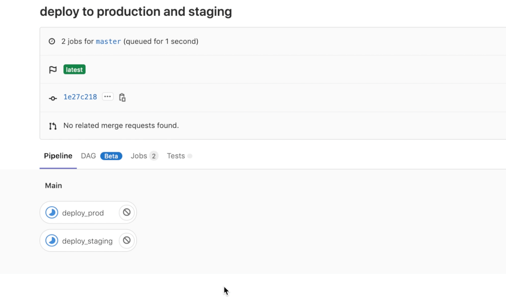
Figure: Deployment of Service Using CI/CD
- Verify in the Console that the service is deployed in the vK8s.
Step 3: Connect and Secure
Connecting the edge app and cloud app requires configuring discovery of cloud app and establishing reachability for edge app on the edge site using virtual hosts. The edge site is then secured using the network layer security policies. Edge app is secured using the application layer security policies and app firewalls.
Note: This chapter provides the details for configuring the required components for virtual host. For detailed instructions on creation of virtual host, see Create and Advertise Virtual Host.
The backend web app services are already deployed on the EKS cluster on the Amazon VPC. These services require discovering and advertising reachability to the edge sites.
Step 3.1: Log into Console and create service discovery.
- Navigate to
Manage>Site Management>Discovery. ClickAdd discovery. - Set a name for the discovery object and select
Kubernetesfor theTypefield. - Select
Virtual Sitefor theWherefield. - Click
Select ref, selectbackend-sitesas the virtual site, and clickSelect ref. - Select
Site Local Networkfor theNetwork Typefield. - Select
K8sfor theDiscovery Service Access Informationfield and selectKubeconfigfor theOneofffield. Click onKubeconfig. - Select
Clear Secretfor theSecret infofield. - Apply Base64 encoding to the K8s kubeconfig and save the output.
- Enter the secret in the
Locationfield.
Note: Append the
string:///string to the copied secret before entering it in theLocationfield.
- Enter
Base64for theSecret Encodingfield and clickApply. - Click
Add discoveryto complete creating the discovery.
Note: You can also encrypt your kubeconfig using the F5 Distributed Cloud Blindfold. For more information, see App Secrets Using Wingman.
Step 3.2: Change to your app namespace and create endpoints.
Select Manage > Endpoints. Click Add endpoint and enter the configuration as per the following guidelines:
-
Enter a name in the
Namefield. -
Enter
Virtual Sitefor theWherefield and select the production virtual site created for theSelect reffield. This example selectsprod-sites. -
Select
Site Local Networkfor the network type. -
Select
Service Selector InfoforEndpoint Specifierfield. -
Select
Kubernetesfor theDiscoveryfield andService Namefor theServicefield. -
Enter
frontend-prod.edge-appsas the service name. Hereedge-appsis the K8s namespace name. -
Enter 80 for the
Portfield. -
Click
Add endpointto create endpoint. -
Repeat the steps to create another endpoint for staging sites. This example sets
staging-sitesas the virtual site andfrontend-stage.edge-appsas the service name.
Step 3.3: Create clusters.
Select Manage>Clusters. Click Add cluster and enter the configuration as per the following guidelines:
-
Enter a name in the
Namefield. -
Select the production sites endpoint created for the
Select endpointfield. -
Select the health check object created for the
Select healthcheckfield. -
Select
Distributedfor theEndpoint Selectionfield. Set0for theConnection TimeoutandHTTP Idle Timeoutfields. -
Click
Add cluster. -
Repeat the above steps to create another cluster for staging sites.
Step 3.4: Add routes toward the created clusters.
Select Manage > Routes. Enter a name and click Add route. Enter the configuration as per the following guidelines:
-
Click
Add match. SelectANYfor theHTTP Methodfield andRegexfor thePath Matchfield. Enter(.*?)for theRegexfield and clickAdd match. -
Select
Destination Listfor theRoute actionfield and clickAdd destination. ClickSelect clusterand select the cluster object created for production sites. Set0for theWeightfield. ClickSelect clusterandAdd destinationto add the cluster. -
Set
0for theTimeoutfield and clickAdd route. -
Click
Add routeagain to create the route. -
Repeat the steps to create another route with the cluster created for the staging sites.
Step 3.5: Add advertise policy.
- Select
Manage>Advertise Policies. ClickAdd advertise policyand selectVirtual Networkfor theWherefield - Click
Select refand selectpublicnetwork. ClickSelect refto add the network. - Select
80as the port. - Click
Add advertise policyto complete creating the advertise policy.
Note: This advertise policy can be used for both production and staging set of sites.
Step 3.6: Encrypt the private key of the certificate using the Distributed Cloud Blindfold.
Use the public key and policy document obtained. This example shows the sample of generating a secret for your application domain. Store the output to a file.
vesctl request secrets encrypt --policy-document secure-kgw-demo-policy-doc --public-key hipster-co-public-key tls.key > tls.key.secretNote: The
tls.keyis the private key of the certificate you generated.
Step 3.7: Add virtual hosts.
Select Manage > Virtual Hosts. Click Add virtual host and set the configuration as per the following guidelines:
-
Enter name, application domain, and your proxy type. This sample uses
HTTP PROXYas the proxy type andhipster-shop.edge-apps-prod.playground.helloclouds.appas the domain. -
Click
Select routeand select previously defined route for the production sites. -
Click
Select advertise policyand select previously created advertise policy. -
Click
Add virtual host. -
Repeat the steps to create another virtual host for the staging environment.
At this point, the apps are accessible through the configured domains. You can verify the same using curl or browser.
Step 3.8: Verify that the egress traffic from one of the pods is allowed.
The following example commands check the egress traffic to IP address 8.8.8.8 for DNS resolution using Google DNS server, and to GitLab.
kubectl --kubeconfig edge-apps-kubeconfig -n edge-apps exec -t frontend-578b65cdff-r48bf -- ping 8.8.8.8 -c 2kubectl --kubeconfig edge-apps-kubeconfig -n edge-apps exec -t frontend-578b65cdff-r48bf -- nslookup github.com 8.8.4.4kubectl --kubeconfig edge-apps-kubeconfig -n edge-apps exec -t frontend-578b65cdff-r48bf -- wget --server-response -O /dev/null https://gitlab.comStep 3.9: Create network policies to allow egress to specific destination and deny all other destinations.
Step 3.9.1: Create network policy rules.
Create network policy rule to allow egress communication to Google DNS server.
-
Change to the
systemnamespace and selectSecurity>Advanced>Network Policy Rules. ClickAdd network policy rule. -
Set a name for the rule and select
Allowfor theActionfield. -
Select
IP Prefixfor theRemote Endpointfield and enter8.8.8.8/32for thePrefixfield. -
Select
udpfor theProtocolfield and53for thePort Rangesfield. -
Click
Add network policy ruleto complete creating the rule. -
Click
Add network policy ruleto create another rule. Set a name, selectAllowforAction, andtcpfor protocol. ClickAdd network policy ruleto create the rule.
Note: The rest of the egress traffic gets implicitly denied.
Step 3.9.2: Create network policies.
-
Select
Security>Advanced>Network Policies. ClickAdd network policy. -
Set a name for the policy and click
Select egress rule. -
Select the previously created rules and click
Select egress ruleto apply the rules. -
Click
Add network policyto complete creating the policy.
Step 3.9.3: Create network policy set.
-
Select
Security>Advanced>Network Policy Sets. ClickAdd network policy set. -
Set a name for the policy set and click
Select policy. -
Select the previously created policy and click
Select policyto apply the policy. -
Click
Add network policy setto complete creating the policy set.
Step 3.10: Create service policies to allow egress to specific domain and deny all other destinations.
Step 3.10.1: Create service policy rules.
Create network policy rule to allow egress communication to GitHub.
-
Select
Security>Advanced>Service Policy Rules. ClickAdd service policy rule. -
Set a name for the rule and select
Allowfor theActionfield. -
Click
Add exact valuein theDomain Matchersection and entergithub.comin theExact Valuesfield. -
Click
Add service policy ruleto complete creating the rule.
Note: The rest of the egress traffic gets implicitly denied.
Step 3.10.2: Create service policies.
-
Select
Security>Advanced>Service Policies. ClickAdd service policy. -
Set a name for the policy and click
First Rule Matchfor theRule Combining Algorithmfield. -
Click
Select Ruleand select the created service policy rule. ClickSelect ruleto apply the rule. -
Click
Add service policyto complete creating the policy.
Step 3.10.3: Create service policy set.
-
Select
Security>Advanced>Service Policy Sets. ClickAdd service policy set. -
Set a name for the policy set and click
Select policy. -
Select the previously created policy and click
Select policyto apply the policy. -
Click
Add service policy setto complete creating the policy set.
Step 3.11: Create network firewall and add to your fleet of sites.
-
Select
Security>Firewall>Network Firewall. ClickAdd network firewall. -
Select
Forward Proxy Service Policy Setin theSelect Forward Policy Configurationfield. Select the service policy created in the previous step for theForward Proxy Service Policy Setfield. -
Select
Network Policy Set (Legacy mode)in theSelect Network Policy Configurationfield. Select the network policy created in the previous step for theNetwork Policy Set (Legacy mode)field. -
Click
Continueto create the network firewall. -
Navigate to
Manage>Fleets. Select your fleet from the list of displayed fleets and click...>Editto open the fleet edit form. -
Click
Select network firewalland select the created firewall. ClickSelect network firewallandSave changesto apply the firewall to the fleet of sites.
Step 3.12: Verify that the policies are effective.
Note: Set up the
KUBECONFIG,pod, andnamespaceenvironment variables before entering the kubectl commands.
- Verify that the egress traffic to GitHub and DNS resolution using the Google DNS is allowed:
kubectl --kubeconfig edge-apps-kubeconfig -n edge-apps exec -t frontend-578b65cdff-r48bf -- nslookup github.com 8.8.8.8
kubectl --kubeconfig edge-apps-kubeconfig -n edge-apps exec -t frontend-578b65cdff-r48bf -- git clone https://github.com/kubernetes-up-and-running/kuard.git- Verify that the rest of the egress traffic is dropped.
kubectl --kubeconfig edge-apps-kubeconfig -n edge-apps exec -t frontend-578b65cdff-r48bf -- nslookup github.com 8.8.4.4
kubectl --kubeconfig edge-apps-kubeconfig -n edge-apps exec -t frontend-578b65cdff-r48bf -- git clone https://gitlab.com/graphviz/graphviz.git
kubectl --kubeconfig edge-apps-kubeconfig -n edge-apps exec -t frontend-578b65cdff-r48bf -- ping 8.8.8.8
Step 3.13: Create application firewall and add to your virtual hosts.
-
Change to your application namespace and select
Security>App Firewall>App Firewall. ClickAdd app firewall. -
Select a name and click
Add firewallto create the firewall in the default blocking mode. -
Navigate to
Manage>Virtual Hostsand select your virtual host from the displayed list. Click...>Editto open the virtual host edit form. -
Scroll down and click
WAF Configto open the WAF config form. SelectWAFfor theWAF Configfield and clickSelect WAF. Select the created app firewall and clickSelect WAFto apply. ClickApplyto add the WAF configuration. -
Click
Save changes.
Step 4: Operate
This chapter shows how perform upgrades to your apps on the edge sites and also perform infrastructure upgrades to the sites. Also, operating your sites includes observability for your deployed applications and this example shows how to use Console to monitor your sites and applications for health and security.
Step 4.1: Perform upgrades to applications.
The DevOps teams usually perform staging upgrades, and when that is successful, the production environment is updated.
Step 4.1.1: Upgrade from your CI/CD pipelines.
- Verify your current application version. This example shows verification using kubectl
kubectl describe deployments frontend-staging | grep label- Open your CI/CD configuration file for staging.
- Update the version of application in the
app.kubernetes.io/versionfield. - Commit the changes and trigger the pipeline.
- Wait for the pipeline to successfully complete and verify the version using kubectl.
- Repeat the steps for production environment with the
frontend-prodas the deployment.
Step 4.1.2: Upgrade from Console.
- Log into Console and change your application namespace.
- Navigate to
Applications>Virtual K8s. Click on your vK8s object to open its deployments view. - Click
...>Editagainst your deployments to open the YAML/JSON edit form and update theapp.kubernetes.io/versionfield value. - Click
Save. - Click
Servicestab to load the services view and click...>Editfor your service to open the YAML/JSON edit form. - Update the
app.kubernetes.io/versionfield value and clickSave.
Step 4.2: Perform infrastructure and operating system software upgrades.
You can perform F5 CE Site software upgrades or OS upgrades from the Console. You can carry out the upgrades for each site individually or for multiple sites using the fleet. The OS upgrade is an A/B upgrade. Firstly, the newest version gets downloaded, gets installed in another partition, and boots up in the new partition created. The health check is carried out and if the health is good, the older version is marked as inactive and continues with the newest version.
Step 4.2.1: Upgrade individual sites.
- Log into Console and navigate to
Sites>Site List. Find your site from the displayed list. - Click on
Upgradebutton in theSW version (Current/Status)for F5 CE Site software upgrade. ClickUpgradein the confirmation window. The field showsIn progressduring the upgrade. - Wait for the upgrade to complete. The
SW version (Current/Status)field showsSuccessfulwhen the upgrade is completed successfully. - Repeat the same steps in the
OS Version (Current/Status)field to perform OS upgrades.
Step 4.2.2: Perform F5 CE Site software upgrade to multiple sites using the fleet.
- Log into Console and navigate to
Manage>Fleets. ClickAdd fleetto open fleet creation form. - Set a name to your fleet and enter a label value for
Fleet Label Valuefield. - Set a version in the
Software Versionfield. An example version iscrt-2020627-310. - Click
Add fleetto create fleet. You can verify your fleet labels in thesharednamespace by navigating toManage>Labels>Known Keys. - In the
systemnamespace, navigate toSites>Site Listand click...>Editto open site edit form. - Click in the
Labelsfield and selectves.io/fleetas the label and select the value as that of the fleet you created. - Scroll down and select
Fleet Version Overridesfor theSite Software Version Overridesfield. - Click
Save. - Repeat the same for the other sites for which you want to apply this software version.
- Verify that the sites now show the applied software version.
Note: You can also edit an existing fleet to apply upgrades and apply the filter
Site Software Override Typeon the site list to display the sites that have software version set by their fleet.
Step 4.2.3: Perform OS upgrade to multiple sites using the fleet.
- Log into Console and navigate to
Manage>Fleets. Find the fleet you created in previous step and click...>Editto open the fleet configuration form. - Scroll down to the
Operating System Versionand enter a version value - Click
Save. - Verify that the sites that are part of this fleet now show the applied OS version.
Step 4.3: Monitor the upgrades using the notifications and alerts.
- Navigate to
Notifications>Audit logs. A list of logs is displayed. - Verify the
Requestfield for the fleet and site upgrades.
Step 4.4: Monitor site health.
- Navigate to
Sites>Site Listand click on your site from displayed sites. This opens the site dashboard. Check the system health, metrics, alerts, and software version section to inspect health, resource consumption, and upgrade information. - Click
Site Statusto check the software and OS version status and upgrade information. - Change to your application namespace and navigate to
Applications>Virtual Sites. A list of cards is displayed with overview information for each virtual site. - Hover over a site (represented by a blue dot) in your virtual site entry to display the CPU and memory consumption of that site.