Deploy a Secure Kubernetes Gateway
Objective
This guide provides instructions on how to create a Secure Kubernetes Gateway using F5® Distributed Cloud Console and F5 Distributed Cloud Mesh.
The steps to create Secure Kubernetes Gateway are:
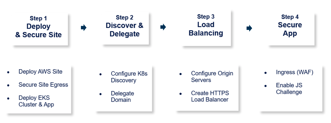
Figure: Steps to Deploy Secure Kubernetes Gateway
The following images shows the topology of the example for the use case provided in this document:
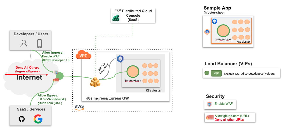
Figure: Secure Kubernetes Gateway Sample Topology
Using the instructions provided in this guide, you can deploy a Secure K8s Gateway in your Amazon Virtual Private Cloud (Amazon VPC), discover the cluster services from that VPC, setup load balancer for them, and secure those services with JavaScript challenge and Web Application Firewall (WAF).
The example shown in this guide deploys the Secure K8s Gateway on a single VPC for an application called as hipster-shop deployed in an EKS cluster. The application consists of the following services:
- frontend
- cartservice
- productcatalogservice
- currencyservice
- paymentservice
- shippingservice
- emailservice
- checkoutservice
- recommendationservice
- adservice
- cache
Prerequisites
-
F5 Distributed Cloud Console SaaS account. If you do not have an account, see Getting Started with Console.
-
Amazon Web Services (AWS) account. This is required to deploy a Distributed Cloud site.
-
F5 Distributed Cloud vesctl utility. See vesctl for more information.
-
Docker.
-
Self-signed or CA-signed certificate for your application domain.
-
AWS IAM Authenticator. See IAM Authenticator Installation for more information.
Configuration
The use case provided in this guide sets up a Distributed Cloud site as Secure K8s Gateway for the ingress and egress traffic for the K8s cluster deployed in the Amazon VPC. The example web application has a front-end service to which all the user requests are sent, and it redirects to other services accordingly. The following actions outline the activities in setting up the Secure K8s Gateway:
-
The frontend service of the application needs to be externally available. Therefore, an HTTPS load balancer is created with origin pool pointing to the frontend service on the EKS cluster.
-
The domain of the load balancer is delegated to Distributed Cloud Services to manage the domains DNS and TLS certificates.
-
Security policies are configured to block egress communication to
Google DNSfor DNS query resolution and allow GitHub, Docker, AWS, and other required domains for code repository management. -
A WAF configuration is applied to secure the externally available load balancer VIP.
-
The JavaScript challenge is set for the load balancer to apply further protection from attacks such as botnets.
Note: Ensure that you keep the Amazon Elastic IP VIPs ready for later use in configuration.
Step 1: Deploy and Secure Site
Perform the following steps to deploy a Distributed Cloud site as the Secure K8s Gateway in your VPC.
Step 1.1: Log into the Console and create cloud credentials object.
- Select the
Multi-Cloud Network Connectservice. - Select
Manage>Site Management>Cloud Credentialsin the configuration. SelectAdd Cloud Credentials. - Enter a name for your credentials object and select
AWS Programmatic Access Credentialsfor theSelect Cloud Credential Typefield. - Enter your AWS access key ID in the
Access Key IDfield.
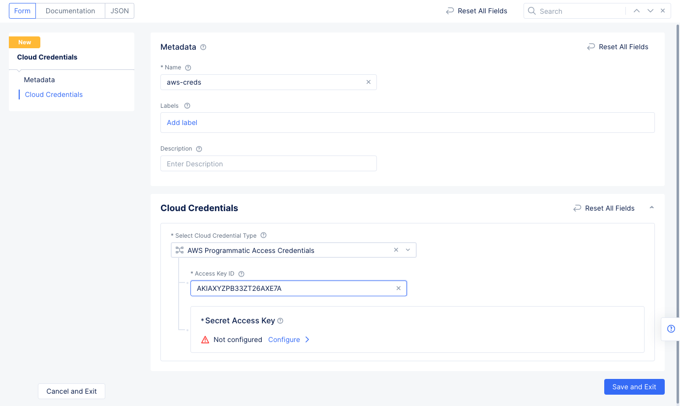
Figure: Credentials Meta and AWS Key Configuration
Step 1.2: Configure AWS secret access key.
- Select
Configureunder theSecret Access Keyfield. - Enter your AWS secret access key into the
Typefield. Ensure that theTextradio button is selected.
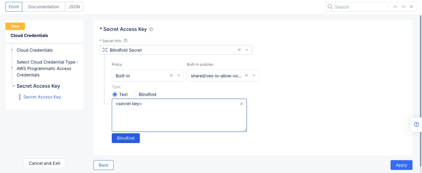
Figure: Secret Key Configuration
-
Select
Blindfoldto encrypt your secret using F5 Distributed Cloud Blindfold. TheBlindfold configuredmessage gets displayed. -
Select
Apply.
Step 1.3: Complete creating the credentials.
Select Save and Exit to complete creating the AWS cloud credentials object.
Step 1.4: Start creating AWS VPC site object.
- Select
Manage>Site Management>AWS VPC Sitesin the configuration menu. SelectAdd AWS VPC Site. - Enter a name for your VPC object in the metadata section.
Step 1.4.1: Configure site type selection.
- Go to
Site Type Selectionsection` and perform the following:- Select a region in the
AWS Regiondrop-down field. This example selectsus-east-2. - Select
New VPC Parametersfor theVPCfield. Enter a name in theAWS VPC Namefield or enterAutogenerate VPC Name. - Enter the CIDR in the
Primary IPv4 CIDR blocksfield. - Select
Ingress/Egress Gateway (Two Interface)for theSelect Ingress Gateway or Ingress/Egress Gatewayfield.
- Select a region in the
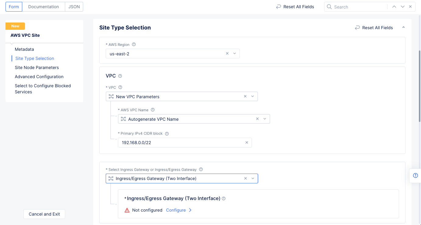
Figure: AWS VPC Site Configuration of Site Type
Step 1.4.2: Configure ingress/egress gateway nodes.
- Select
Configureto open the two-interface node configuration wizard. - Select
Add Itemand enter the configuration using the following guidelines. - Select an option for the
AWS AZ namefield that matches the configuredAWS Region. - Select
New Subnetfor theWorkload Subnetfield in theWorkload Subnetsection. Enter a subnet address in theIPv4 Subnetfield. - Similarly configure a subnet address for the
Subnet for Outside Interfacesection. - Select
Applyto complete the two-interface node configuration.
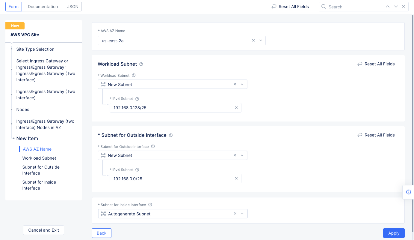
Figure: Ingress/Egress Gateway Nodes Configuration
Step 1.4.3: Configure the site network firewall policy.
-
Go to
Site Network Firewallsection and selectActive Firewall Policiesfor theManage Firewall Policyfield. Use theFirewall Policydrop-down menu to selectAdd Item. Enter the configuration using the following guidelines:- Enter a name and enter a CIDR for the
IPv4 Prefix Listfield. This CIDR should be within the CIDR block of the VPC.
- Enter a name and enter a CIDR for the
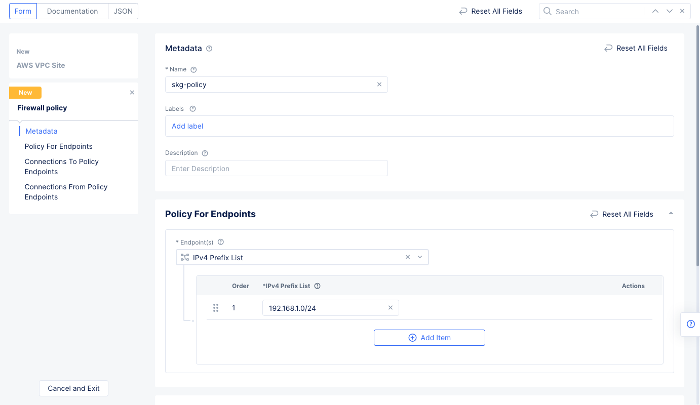
Figure: Network Policy Endpoint Subnet
- Select
ConfigureunderIngress Rulesin theConnections To Policy Endpointssection. - Select `Add Item' to add an ingress rule, and enter the following configuration:
- Enter a name for the
Rule Namefield and selectAllowfor theActionfield. - Select
Any Endpointfor theSelect Other Endpointfield. - Select
Match Protocol and Port Rangesfor theSelect Type of Traffic to Matchfield. - Select
TCPfor theProtocolfield. - Select
Add itemunderList of Port Ranges, and then enter a port range. - Select the
Applybutton at the bottom to save the ingress rule, and then selectApplyto complete the ingress rules configuration.
- Enter a name for the
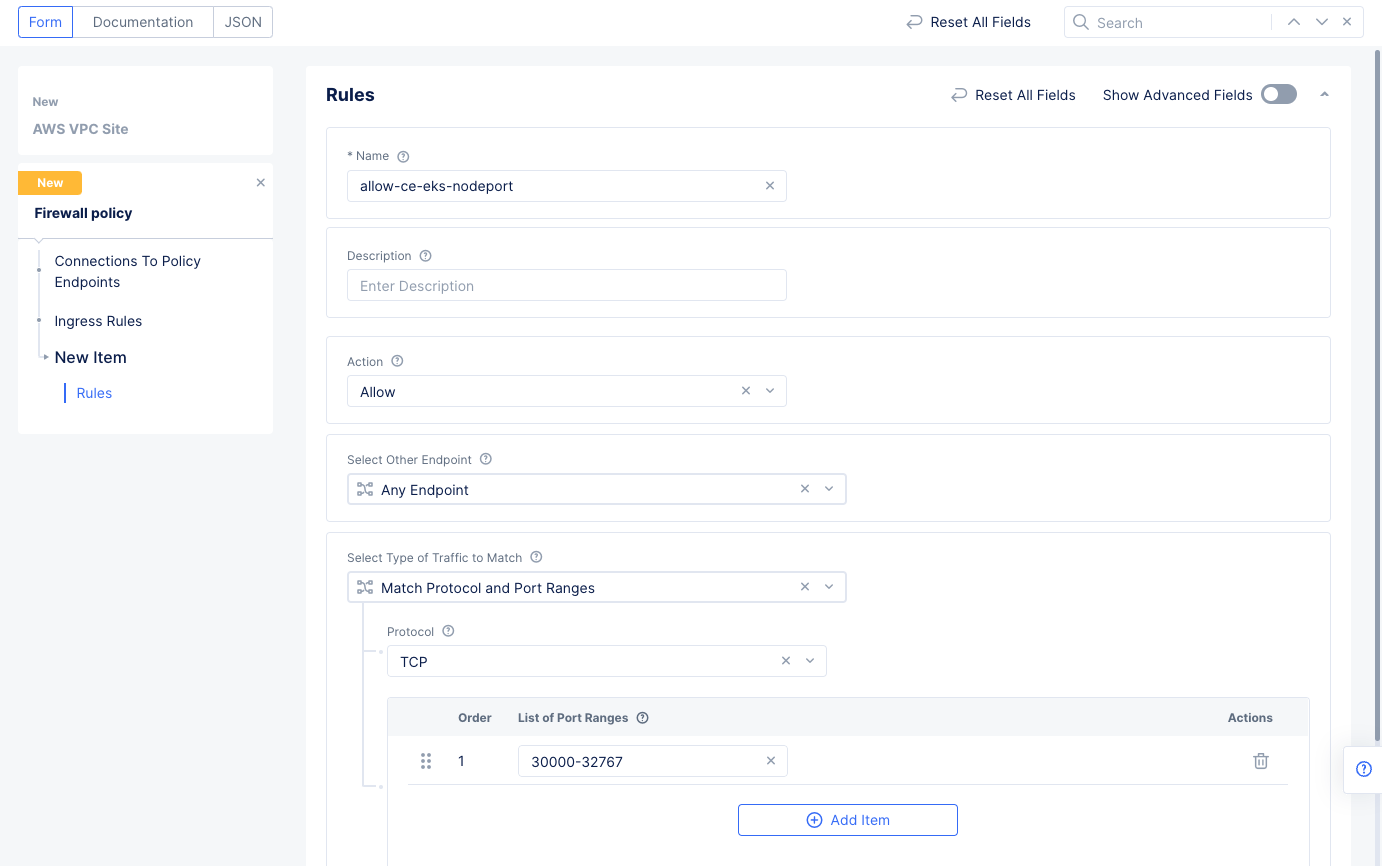
Figure: Network Policy Ingress Rule
- Select
ConfigureunderEgress Rulesin theConnections From Policy Endpointssection. - Select
Add Itemto add an egress rule to theEgress Ruleslist, and enter the following configuration:- Enter a name for the
Rule Namefield and selectDenyfor theActionfield. This example configures a deny rule for Google DNS query traffic. - Select
IPv4 Prefix Listfor theSelect Other Endpointfield and enter8.8.4.4/32for theIPv4 Prefix Listfield. - Select
Match Application Trafficfor theSelect Type of Traffic to Matchfield. - Select
DNSfor theApplication Protocolsfield. - Select the
Applybutton at the bottom to save the egress rule.
- Enter a name for the
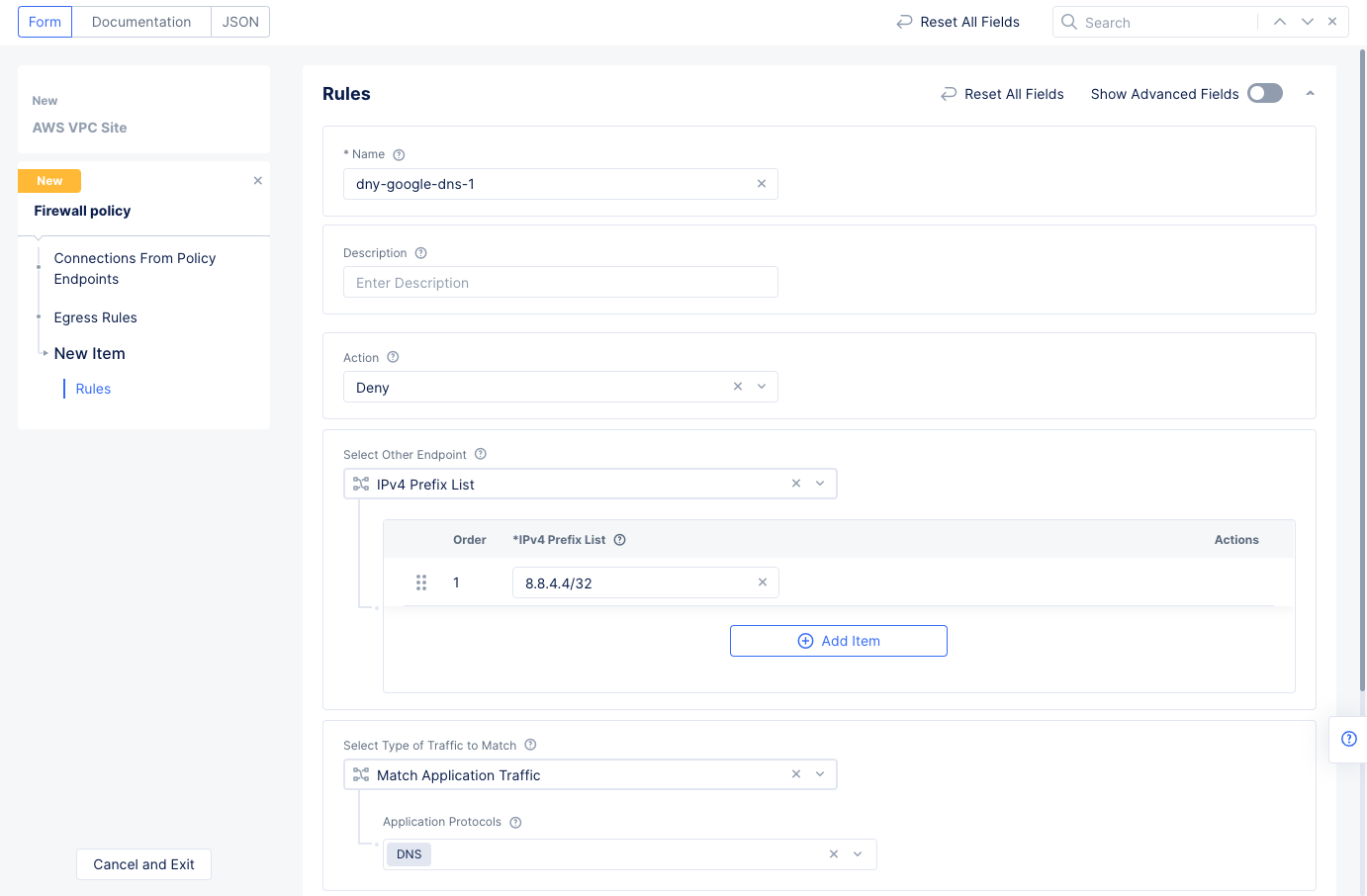
Figure: Network Policy Egress Rule
- Select
Add itemand configure another rule of typeallowfor the endpoint prefix8.8.8.8/32. This is another Google DNS endpoint prefix.- Select
Match Application Trafficfor theSelect Type of Traffic to Matchfield. - Select
DNSfor theApplication Protocolsfield. - Select the
Applybutton at the bottom to save the egress rule.
- Select
- Select
Add itemand configure another rule withAllowaction to allow rest of all egress TCP traffic. Select theApplybutton at the bottom to save the egress rule.
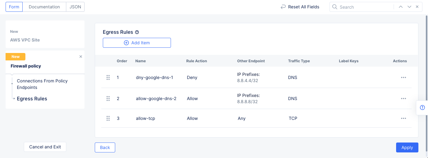
Figure: Network Policy Egress Rule
-
Select
Applyto save the egress rules list. -
Select
Continueto apply the network policy configuration.
Step 1.4.4: Configure the site forward proxy policy.
-
Select
Enable Forward Proxy and Mange Policiesfor theManage Forward Proxy Policyfield. Use theForward Proxy Policiesdrop-down menu to selectAdd Item. Enter the configuration using the following guidelines:- Enter a name and select
All Forward Proxies on Sitefor theSelect Forward Proxyfield. - Select
Allowed connectionsfor theSelect Policy Rulessection. - Select
Add Itemunder theTLS Domainsfield. SelectExact Valuefrom the drop-down list of theEnter Domainfield and entergitlab.comfor theExact Valuefield. SelectApplyto add this domain to the TLS Domains list. Repeat this step several times using the following specifics: - Repeat the step above for
github.com. - Repeat the step again for each of the following domains with the
Suffix Valuetype.gcr.iostorage.googleapis.comdocker.iodocker.comamazonaws.com
- Enter a name and select
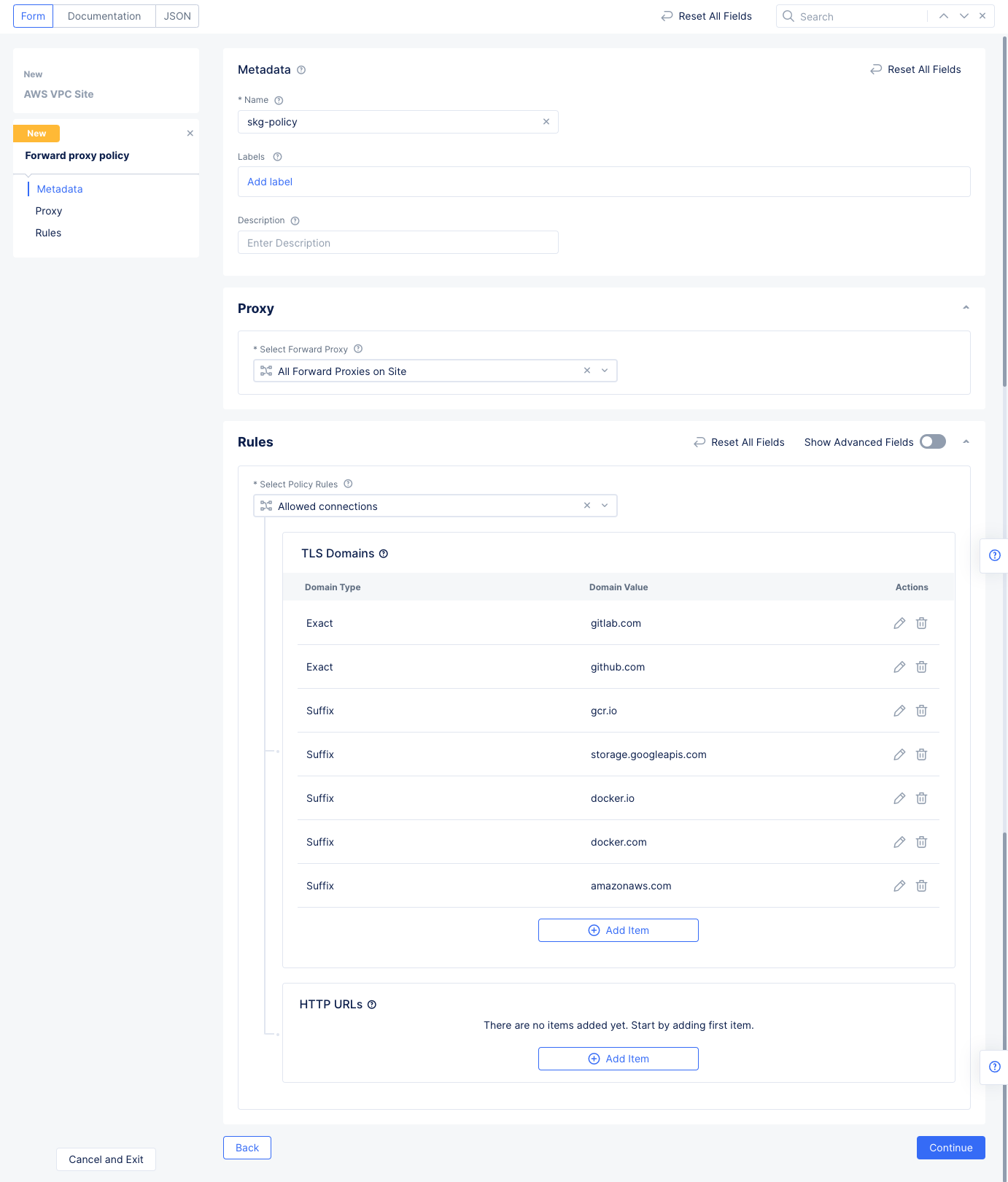
Figure: TLS Domains
Note: The
Allowed connectionsoption allows the configured TLS domains and HTTP URLs. Everything else is denied.
- Select
Continueto apply the forward proxy policy configuration.
Step 1.4.5: Configure static route for the inside interface towards the EKS CIDR.
- Enable
Show Advanced Fieldsin theAdvanced Optionssection. - Select
Manage Static Routesfor theManage Static Routes for Inside Networkfield, and then selectAdd Itemto add a route to theList of Static Routes.- Select
Simple Static Routefor theStatic Route Config Modefield. - Enter a route for your EKS subnet in the
Simple Static Routefield. - Select
Add Itemto save the route to the list.
- Select
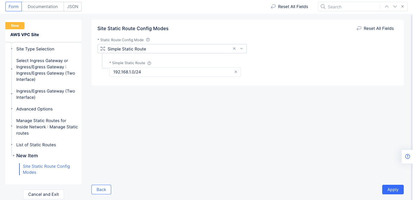
Figure: Static Roue Configuration
- Select
Applyto return to the Ingress/Egress Gateway configuration. - Select
Applyto return to the AWS VPC site configuration screen.
Step 1.4.6: Complete AWS VPC site object creation.
- Select
Automatic Deploymentfor theSelect Automatic or Assisted Deploymentfield. - Select the AWS credentials created in Step 1.1 for the
Automatic Deploymentfield. - Select an instance type for the node for the
AWS Instance Type for Nodefield in theSite Node Parameterssection. - Enter your public SSH key in the
Public SSH keyfield. This is required to access the site once it is deployed.
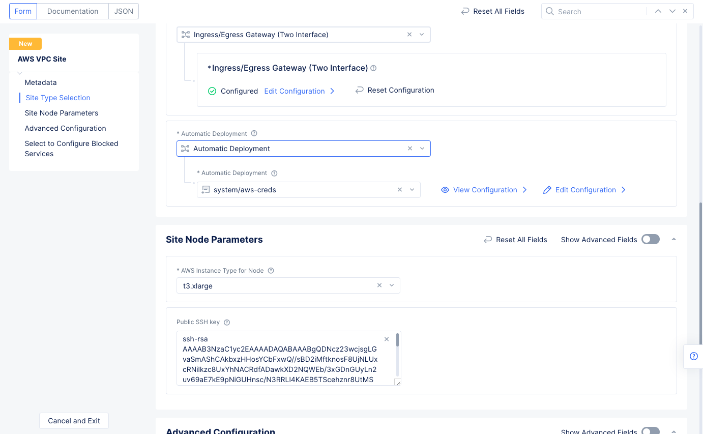
Figure: Automatic Deployment and Site Node Parameters
- Select
Save and Exitto complete creating the AWS VPC object. The AWS VPC site object gets displayed.
Step 1.5: Deploy AWS VPC site.
- Select the
Applybutton for the created AWS VPC site object. This will create the VPC site.
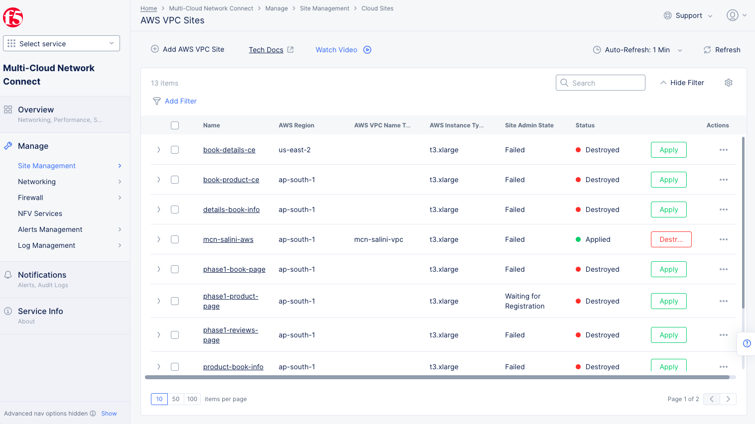
Figure: Terraform Apply for the VPC Object
- Select
...>Terraform Parameters. SelectApply Statustab. Copy the VPC ID from thetf_outputsection.
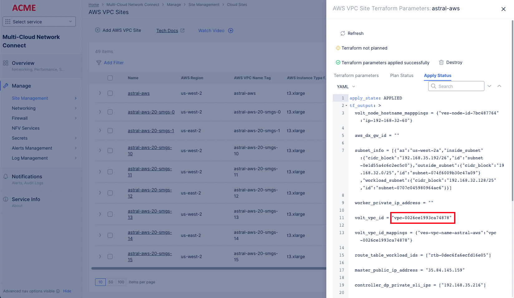
Figure: VPC ID from Terraform Apply Status
Step 1.6: Deploy the EKS cluster and hipster shop application in it.
Step 1.6.1: Create a terraform variables (tfvars) file.
In a new empty directory, create a Terraform file with .tfvars extension and populate it using JSON with the following values:
{ "aws_access_key": "foobar", "aws_secret_key": "foobar", "name": "<vpc_object_name>", "vpc_id": "<vpc_id>"}Note: The values in the file should match those used in the previous steps:
- For AWS access and secret keys, use the same values that you used in steps 1.1 and 1.2.
- For name, use the VPC object name you used in step 1.4.
- For VPC ID, use the value you copied in step 1.5.
If the namespace has already been created on the EKS site, then add "create_namespace": 0:
{ "aws_access_key": "foobar", "aws_secret_key": "foobar", "name": "<vpc_object_name>", "vpc_id": "<vpc_id>" "create_namespace": 0}Step 1.6.2: Deploy EKS.
Set the $ACTION environmental variable to apply (note the $ACTION value can be plan, apply or destroy):
export ACTION=planRun the following command to deploy the EKS cluster:
docker run --rm -it \ --env AWS_ACCESS_KEY_ID=$AWS_ACCESS_KEY_ID \ --env AWS_SECRET_ACCESS_KEY=$AWS_SECRET_ACCESS_KEY \ --env VAR_FILE_NAME=test.json \ -v ${PWD}:/terraform/templates/ \ gcr.io/solutions-team-280017/eks_only \ /terraform/templates/$ACTIONStep 2: Discover and Delegate
Discovering services in the VPC requires configuring service discovery objects for the front-end service. Also, this includes delegating the domain to Distributed Cloud Services to manage the DNS and certificates for the domain.
Perform the following steps for discovering services.
Step 2.1: Create a service discovery object.
Log into the Console and select the Multi-Cloud App Connect service. Navigate to Manage > Service Discoveries, select Add Discovery, and enter the following configuration:
- Enter a name in the
Namefield. - In the
Wheresection,- Select
Sitefor theVirtual-Site or Site or Networkfield. - Select the site you created as part of Step 1 in the
Reference field. - Select the
Site Local Inside Networkfor theNetwork Typefield.
- Select
- Select
K8S Discovery Configurationfor theSelect Discovery Methodfield, selectConfigureto set up the discovery method. - Select
Kubeconfigfor theSelect Kubernetes Credentialsfield. SelectConfigureunder theKubeconfigfield to open the secret configuration.- Select
Textfor the blindfold secretType, and then enter the kubeconfig downloaded as part of Step 1 in theTextfield.
- Select
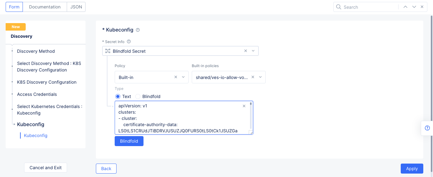
Figure: Secret Encryption
- Select
Blindfoldand wait until the Blindfold process is complete. SelectApplyto save the secret.
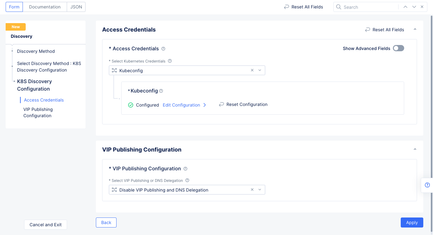
Figure: Discovery Object Configuration
- Select
Applyto save the K8s discovery configuration, and then SelectSave and Exitto create the discovery object.
Verify in Console that the discovery object is created and discovered services. Select ... > Show Global Status for the discovery object to view the discovered services.
Step 2.2: Delegate your domain to F5 Distributed Cloud.
For details how to delegate your domain, see F5 Distributed Cloud Domain Delegation.
Step 3: Load Balancer
An HTTP load balancer must be configured to make the frontend service externally available. As part of the HTTP load balancer, the origin pools are created that define the origin servers where the frontend service is available.
Perform the following to configure load balancer:
Step 3.1: Create a namespace and change to it.
- Select the
Administrationservice. - Select
Personal Management>My Namespaces, and selectAdd namespace.
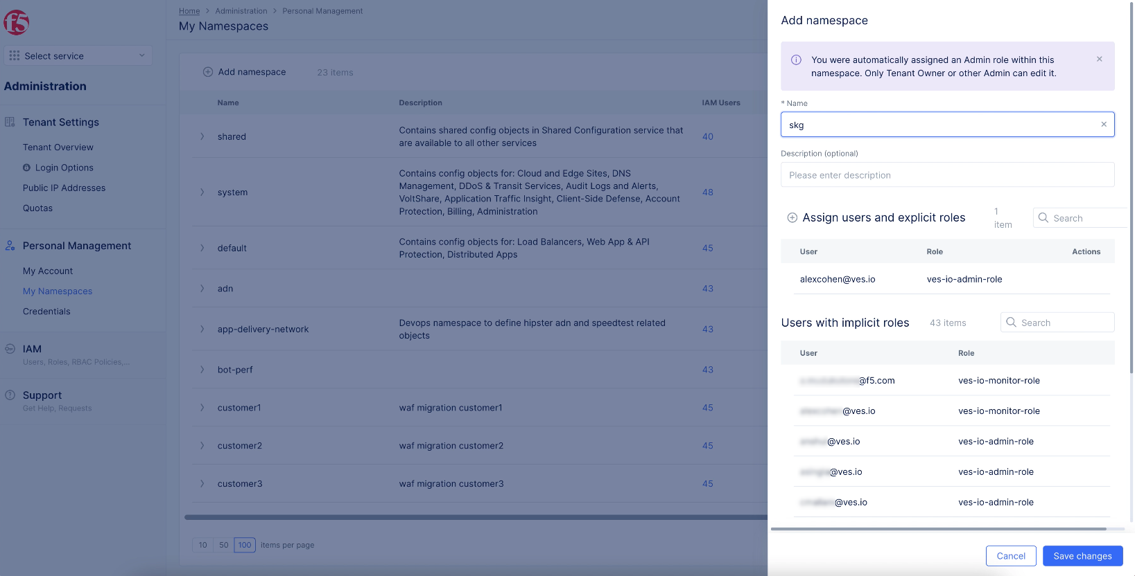
Figure: Add a Namespace
- Enter a name and select
Add namespace. - Change to the
Multi-Cloud App Connectservice. - Select on the namespace drop-down menu and select your namespace to change to it.
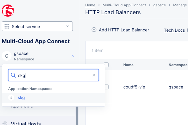
Figure: Change to Application Namespace
Step 3.2: Create HTTP load balancer.
Select Manage > Load Balancers in the configuration menu and HTTP Load Balancers in the options. Select Add HTTP load balancer.
Step 3.2.1: Enter metadata and set basic configuration.
- Enter a name for your load balancer in the metadata section.
- Enter a domain name in the
Domainsfield. Ensure that its sub-domain is delegated to Distributed Cloud Services. This example setsskg.quickstart.distribugteappsonvolt.orgdomain. Theskgpart is a prefix and thequickstart.distribugteappsonvolt.orgpart is a domain delegated that is already setup on this tenant. - Select
HTTPS with Automatic Certificatefor theLoad Balancer Typefield.
Step 3.2.2: Configure origin pool.
- Select
Add Itemin theOriginssection. - Use the
Origin Poolpull-down to selectAdd Item. - In the pool creation form, enter a name for your pool in the metadata section.
- In the
Origin Serverssection, selectAdd Item, SelectK8s Service Name of Origin Server on given Sites, - In the
Select Type of Origin Serverfield ofBasic Configurationsection, selectk8s Service Name of Origin Server on given Sites.- Enter service name in the
<servivename.k8s-namespace>format for theService Namefield. This example setsfrontend.hipsteras the service name. - Select
Sitefor theSite or Virtual Sitefield and select the site you created in Step 1. - Select
Inside Networkfor theSelect Network on the sitefield. - Select
Applyto save the origin server.
- Enter service name in the
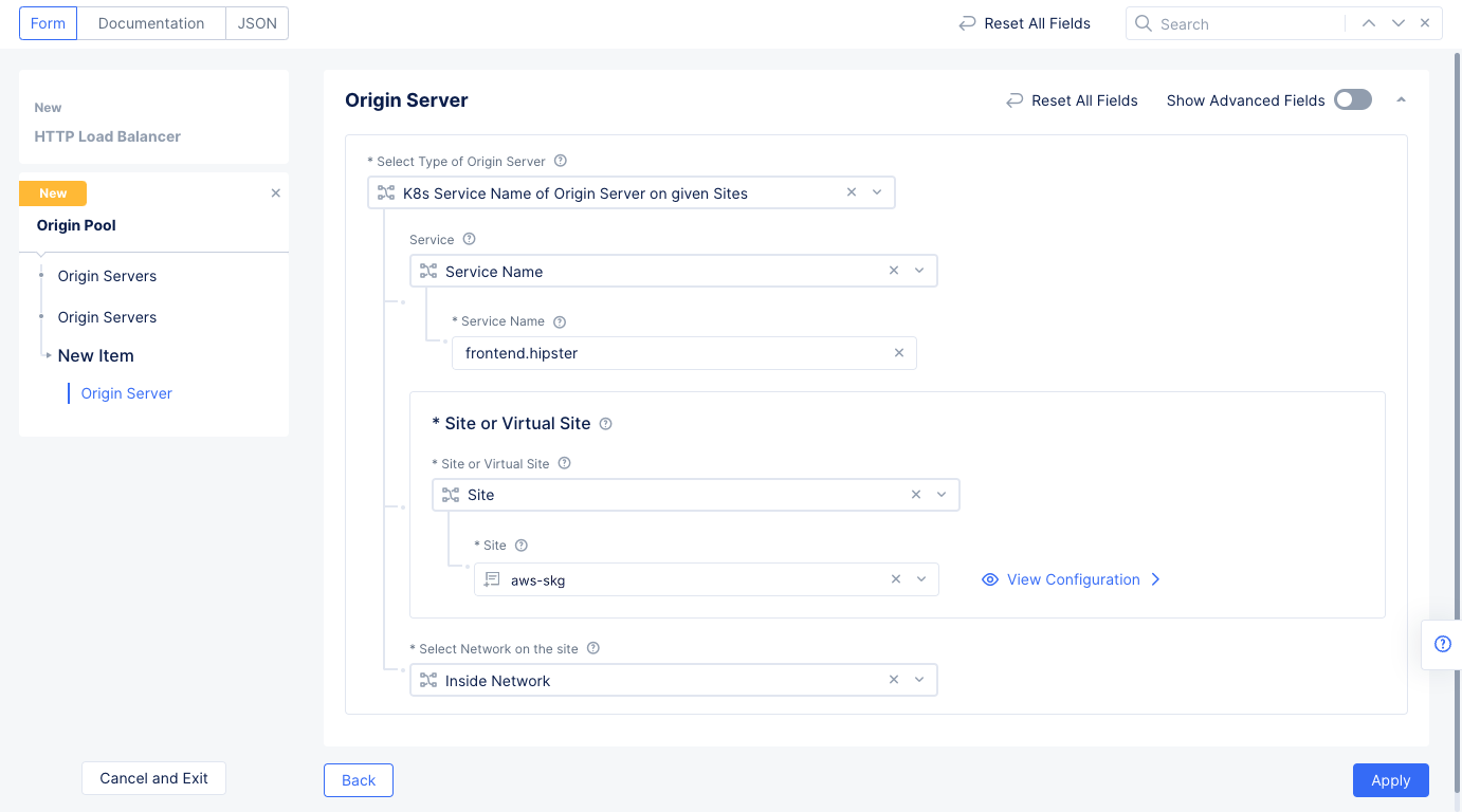
Figure: Origin Pool Configuration
- Enter
80in thePortfield. - Select
Continueto save the origin pool. - Select
Applyto add the origin pool to the load balancer.
Step 3.2.3: Complete load balancer creation.
Scroll down and select Save and Exit to create load balancer. The load balancer object gets displayed with TLS Info field value as DNS Domain Verification. Wait for it to change to Certificate Valid.
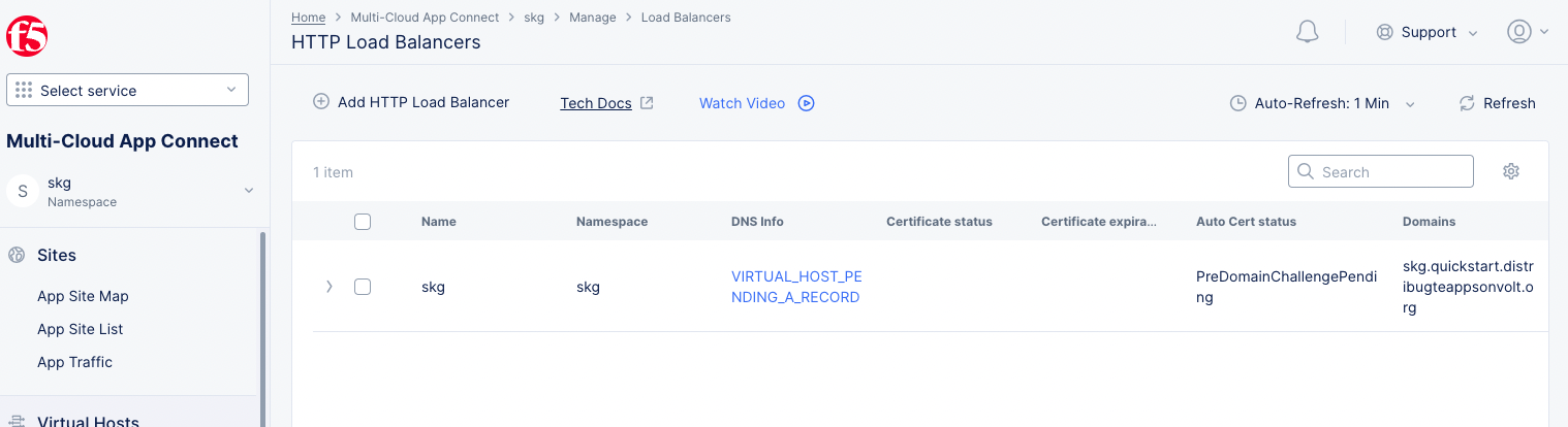
Figure: Created HTTP Load Balancer
The load balancer is now ready, and you can verify it by accessing the domain URL from a browser.
Step 4: Secure App
Securing the ingress and egress traffic includes applying WAF and JavaScript challenge to the load balancer.
Perform the following steps to configure WAF and JavaScript challenge:
Step 4.1: Configure WAF to load balancer.
- Select the
Multi-Cloud App Connectservice and select the namespace you created previously. - Select
Manage>Load Balancersfrom the configuration menu and selectHTTP Load Balancersin the options. Select...>Manage Configurationfor the load balancer for which WAF is to be applied. Then selectEdit Configurationto make changes. - Scroll down to the
Web Application Firewallsection and selectEnable. - Use the
Enabledrop-down menu to selectAdd Item.
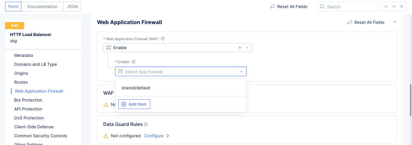
Figure: Security Configuration for Load balancer
- Set a name for the WAF and select
Blockingfor theEnforcement Modefield. SelectContinueto create WAF and apply to the load balancer.
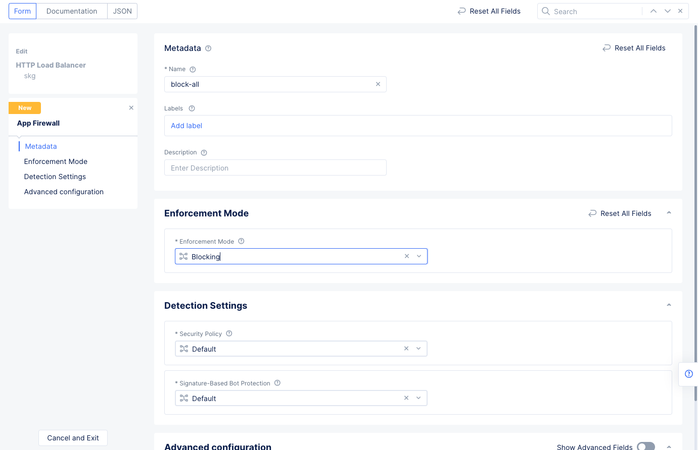
Figure: WAF Configuration
-
Select
Save and Exitto save load balancer configuration. -
Verify that the WAF is operating. Enter the following command to apply an SQL injection attack:
https://skg.quickstart.distributedappsonvolt.org/v=SELECT%20sqlite_version%28%29The URL rejection result indicates that the WAF is operational and blocks the SQL injection attempt.
- Inspect the WAF events from the load balancer monitoring view. Navigate to
Overview>Applicationsto see an overview of all load balancers. - Scroll down to the
Load Balancerssection and select the load balancer previously created to get more details for that specific load balancer.
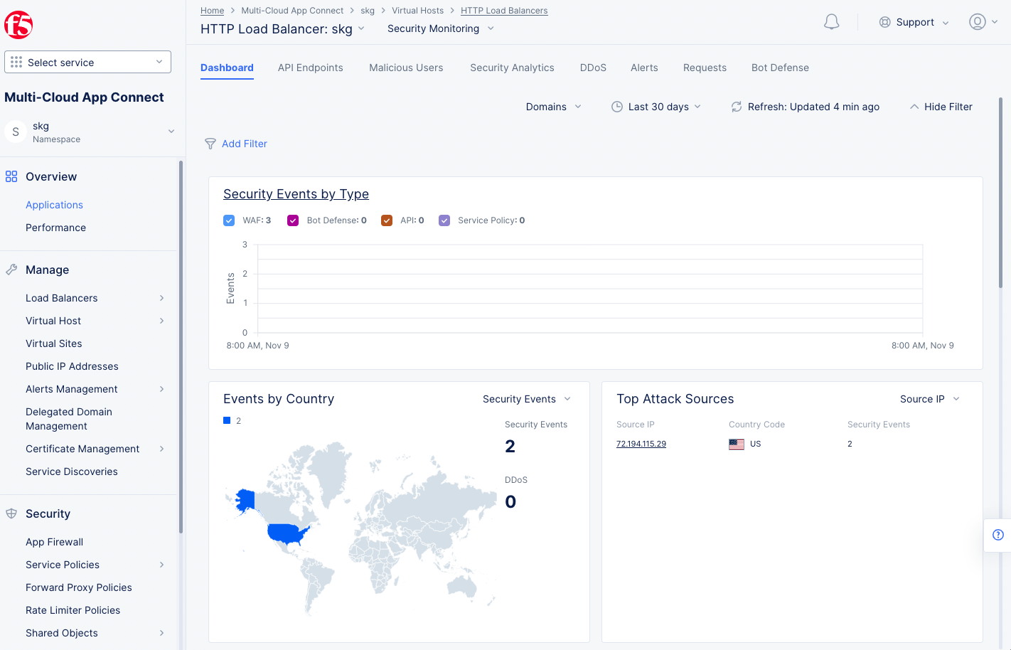
Figure: Load Balancer App Firewall View
Step 4.2: Configure javascript challenge for the load balancer.
-
Select the
Web App & API Protectionservice and select the namespace you created previously. -
Select
Manage>Load Balancers>HTTP Load Balancersin the left menu. Select...>Manage Configurationfor the load balancer for which JavaScript challenge is to be applied. -
Click
Edit Configurationin the upper right. -
In the
Common Security Controlssection, turn on theShow Advanced Fieldstoggle. -
Select
Javascript Challengefrom theMalicious User Mitigation And Challengesdrop-down menu, and then clickConfigure. -
Enter
3000and1800for theJavascript DelayandCookie Expiration periodfields respectively. This sets the delay to 3000 milliseconds and cookie expiration to 1800 seconds. -
Enter a base-64 message into the
Custom Message for Javascript Challenge. This example uses<p>Please wait.</p>for the message, which encodes toPHA+UGxlYXNlIHdhaXQuPC9wPg==.
Note: https://www.base64encode.org/ is a convenient site for encoding/decoding Base64 content.
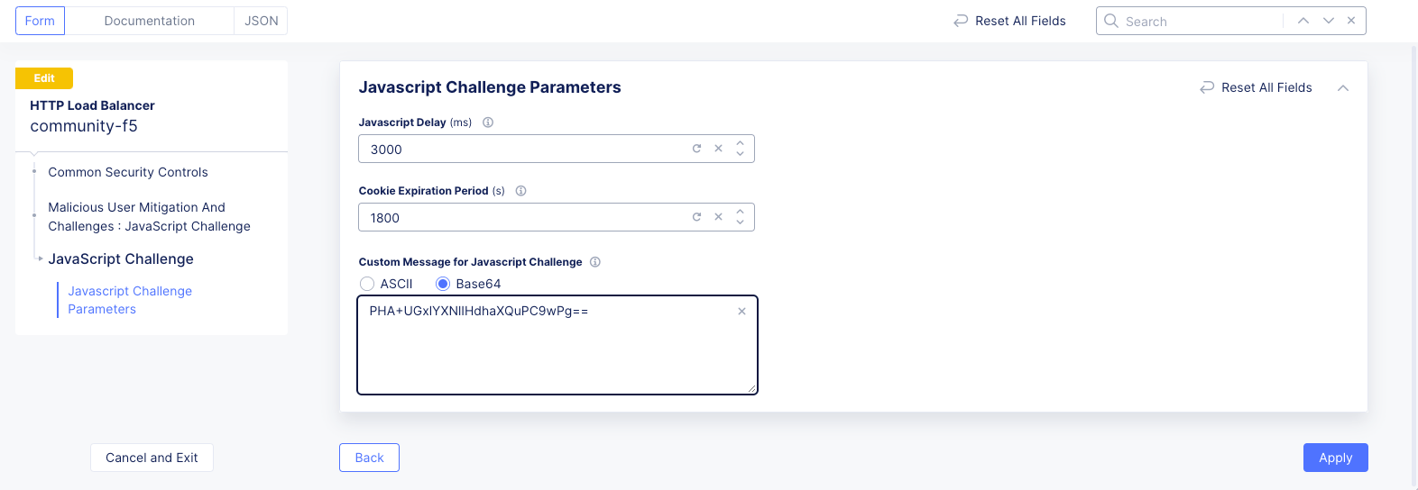
Figure: Javascript Challenge Configuration
- Select
Applyto apply the JavaScript challenge to load balancer.
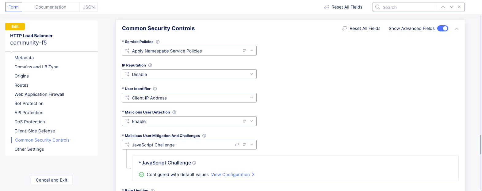
Figure: Javascript Challenge Applied to Load Balancer
-
Select
Save and Exitto save load balancer configuration. -
Verify that the JavaScript challenge is applied. Enter your domain URL from a browser. The JavaScript challenge default page appears for 3000 milliseconds before loading the hipster website.
-
For more information on creating a JavaScript challenge, see Configure JavaScript Challenge.