Deploy Secure Mesh Site v2 in Azure (ClickOps)
Objective
This guide provides instructions on how to create a Customer Edge (CE) Site using F5® Distributed Cloud Console and Microsoft Azure Console and deploy to an Azure Virtual Network (VNet).
Important: This guide does not provide instructions on how to deploy an F5® App Stack Site.
Planning
Read the following documents before deploying a Secure Mesh Site in any provider environment:
- Understanding F5 Distributed Cloud - Customer Edge (CE)
- CE Datasheet
- CE Supported Platforms Guide
- Customer Edge Site Sizing Reference
- CE Performance Guide: Contact your account representative on CE performance-related information.
- Proxy for CE Registration and Upgrades Reference
- Secure Mesh Sites v2 Frequently Asked Questions
- Customer Edge Registration and Upgrade Reference
- F5 Customer Edge IP Address and Domain Reference for Firewall or Proxy Settings
General Prerequisites
The following general prerequisites apply:
-
A Distributed Cloud Services Account. If you do not have an account, see Getting Started with Console.
-
An account with Microsoft Azure. See Azure VNet Policies and Permissions Reference for permissions needed to deploy Site.
-
Resources required per node: Minimum 8 vCPUs, 32 GB RAM, and 80 GB disk storage. For a full listing of the resources required, see the Customer Edge Site Sizing Reference guide. All the nodes in a given CE Site should have the same resources regarding the compute, memory, and disk storage. When deploying in cloud environments, these nodes should use the same instance flavor.
-
Customer Edge deployments require connectivity to F5 Distributed Cloud. See the F5 Customer Edge IP Address and Domain Reference for Firewall or Proxy Settings guide for the list of IP addresses and domain names that need to be allowed.
-
F5 assumes that the resource group exists with a virtual network, including a minimum of two subnets: one for the Site Local Outside (SLO) and one for the Site Local Inside (SLI). The CE generally references the SLO interface as
eth0and the SLI interface aseth1. For three-node clusters, F5 recommends that you have three different subnets in three different availability zones. -
For a single-NIC deployment (ingress gateway), only a single subnet (SLO) is required.
-
The new Secure Mesh Site workflow enables you to have up to eight interfaces. However, these interfaces should be in different subnets. Therefore, make sure you have the required subnets available before creating the CE Site nodes.
-
If you are deploying the CE Site with High Availability (HA) enabled, the Internet Control Message Protocol (ICMP) must be opened between the CE nodes on the Site Local Outside (SLO) interfaces. This is needed to ensure intra-cluster communication checks.
Important: After you deploy the CE Site, the IP address for the SLO interface cannot be changed. Also, the MAC address cannot be changed.
Configuration Overview
To create a Secure Mesh Site with Microsoft Azure, here are the high-level steps:
- Site object configuration: Create and configure a Secure Mesh Site object using F5 Distributed Cloud Console.
- Node creation prerequisites: Create objects that are associated with the CE nodes, including network security groups, SSH key pairs, and more.
- Node management: Use Launch Instance deployment method to create the CE nodes. Each CE node is a virtual machine (VM).
- Network interface management: Add additional interfaces on the nodes, if necessary.
Important: The first interface of a CE node must be mapped to the Site-Local Outside (SLO) VRF which should allow connectivity to the F5 Distributed Cloud Services.
This document describes one- and two-interface deployments for CE sites with HA disabled (single node) and HA enabled (three-node cluster).
Procedure
This guide shows you how to create a single-node mesh site with dual interfaces (ingress/egress gateway). However, this guide also incorporates the differences that you can follow to successfully deploy an Azure CE Site in any supported combination of nodes and interfaces.
Create Site Object
-
Create a secure mesh Site object in Distributed Cloud Console. Refer to the Create Secure Mesh Site guide.
-
Set the Provider Name option to Azure.
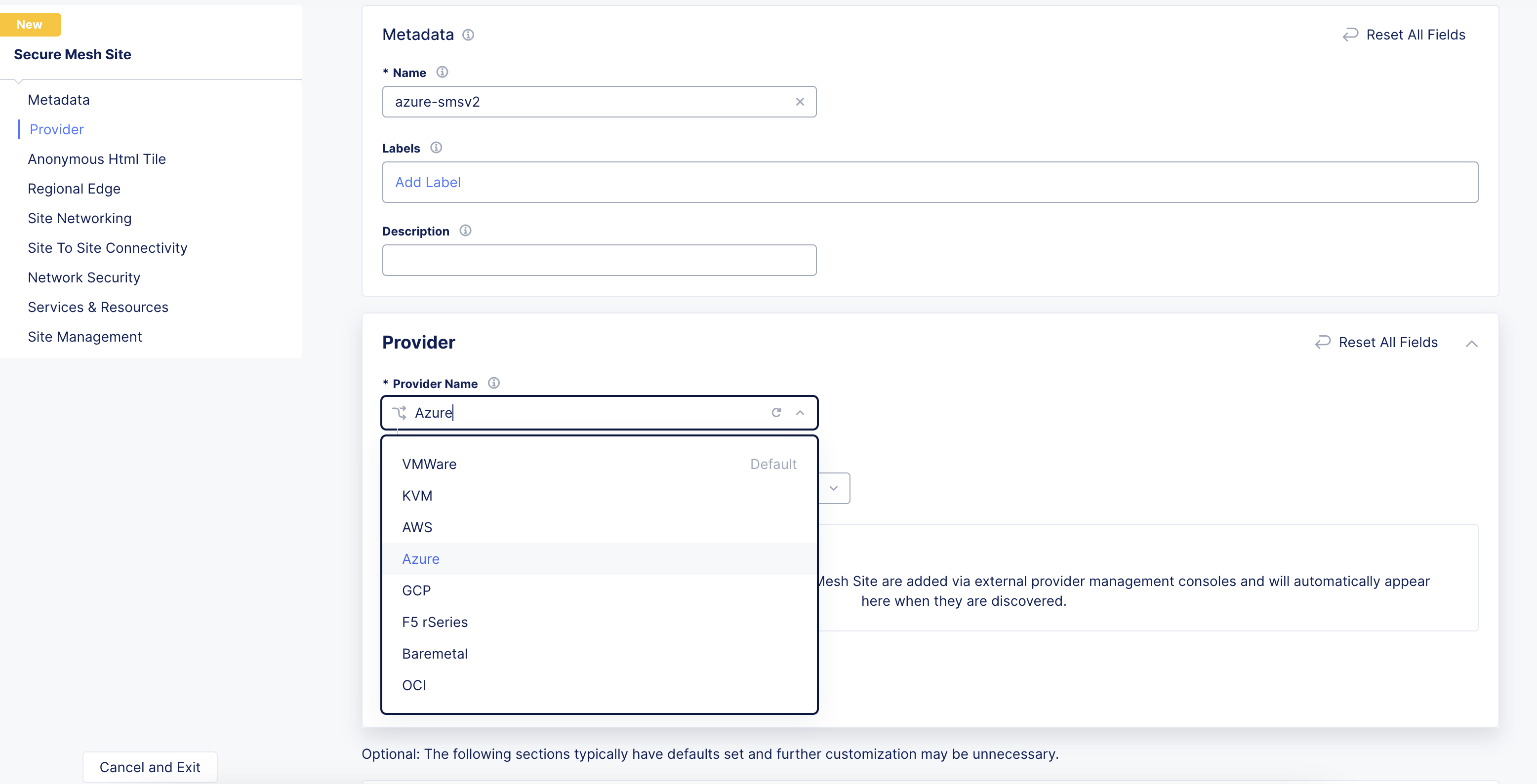
Figure: Provider Type
- For High Availability, choose an option. If it is Disabled, then the CE Site only supports one node. If it is Enabled, the CE Site requires three nodes. Additional nodes can only be added to CE sites when HA is Enabled.
Important: The High Availability mode cannot be changed after the CE Site is created.
-
Leave the other options with their default values. These options have intelligent default values and do not need further configuration. Refer to the Create Secure Mesh Site guide for more information on these options.
-
Click Add Secure Mesh Site.
Create Network Security Group
The CE site’s instance security is internally managed by the CE data path. Therefore, you must configure a Network Security Group with allow-all rules for both inbound and outbound traffic to be used with the Site deployment.
Step 1: Navigate to security group creation page.
In Azure Console, navigate to the Network security groups service.
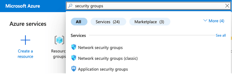
Figure: Network Security Groups
Step 2: Create and configure security group.
-
Click Create.
-
Assign the new security group to your resource group.
-
Give the network security group an indicative name. For example, f5-ce-external-network-security-group.
-
Click Review + create.
-
After you create the network security group, click on it to set up the inbound and outbound rules.
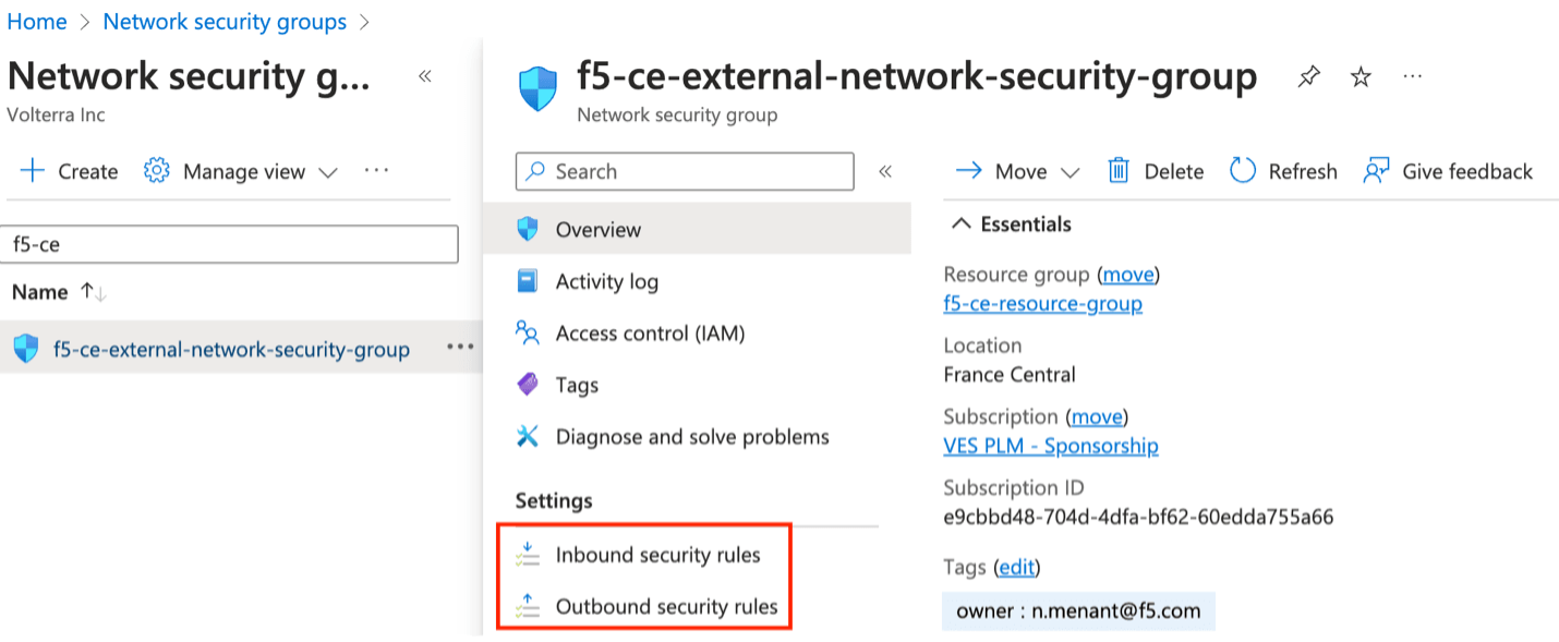
Figure: Network Security Group
Step 3: Create inbound rules.
Make sure you add rules for the following:
- Allow SSH from the instance. Azure figures out the public IP address that a user is configuring from and allows it. You can also use the custom option and enter your corporate public address space.
- Allow ICMP for troubleshooting.
- Allow TCP Port 65500 for the local UI on the CE.
- For three-node clusters, ensure that traffic is allowed between the nodes.
Note: When creating load balancers to publish applications, you need to add additional rules in your network security group to accept the traffic that comes to your virtual IP address (VIP).
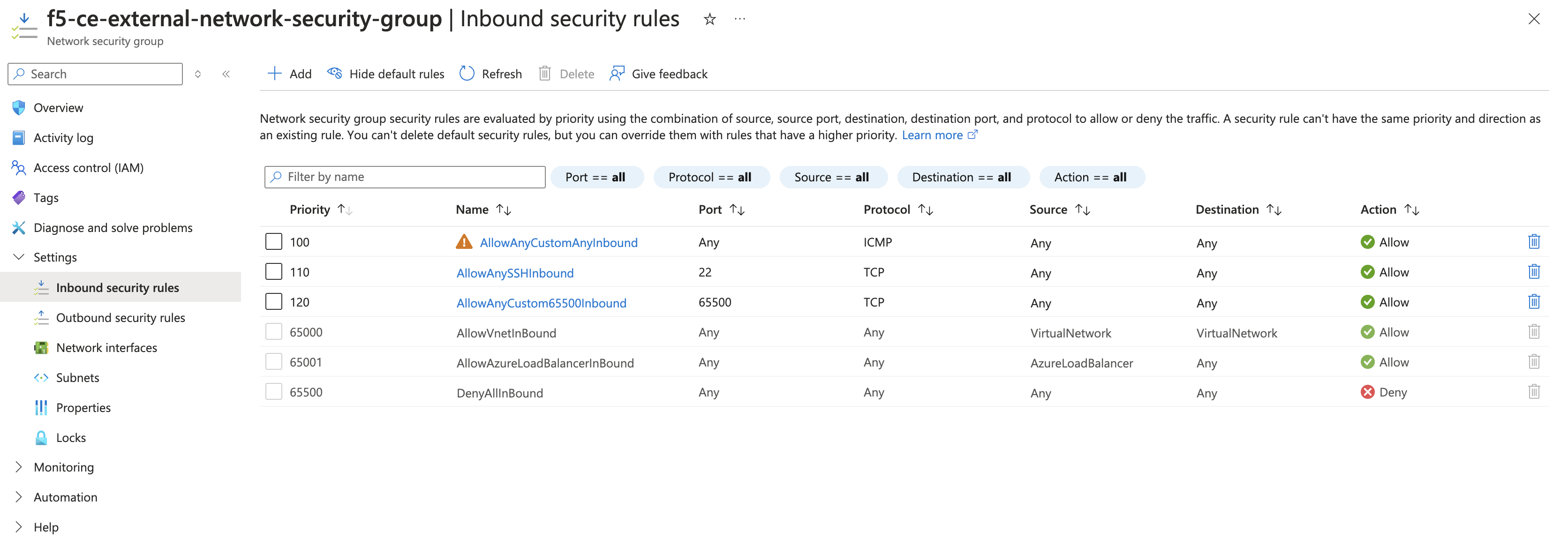
Figure: Inbound Rules
Step 4: Create outbound rules.
Confirm you have an allow-all policy for egress traffic. This is the default configuration.
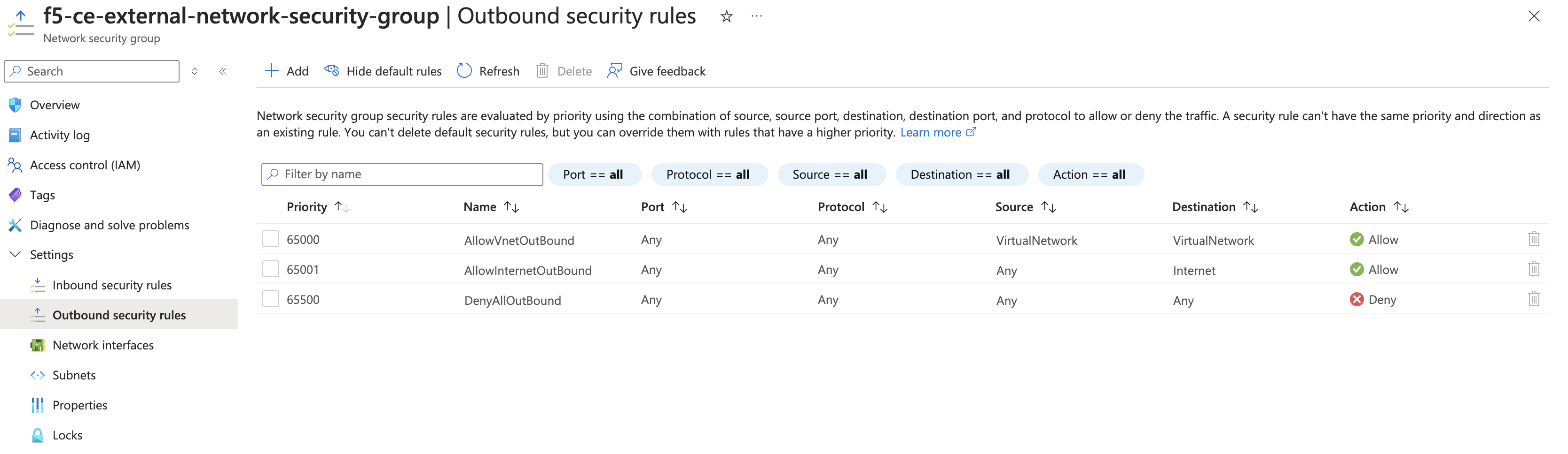
Figure: Outbound Rules
Step 5: Verify rules.
In the overview section for your network security group, confirm the rules are as desired.
Create SSH Key Pair
You need to create a key pair for SSH login into the VM instance for troubleshooting purposes.
Step 1: Navigate to SSH key creation page.
-
In Azure Console, navigate to the SSH keys service.
-
Click Create.
Step 2: Configure key pair.
-
Verify Subscription and Resource group are correctly selected.
-
In the Key pair name field, enter a name.
-
Click Review + create.
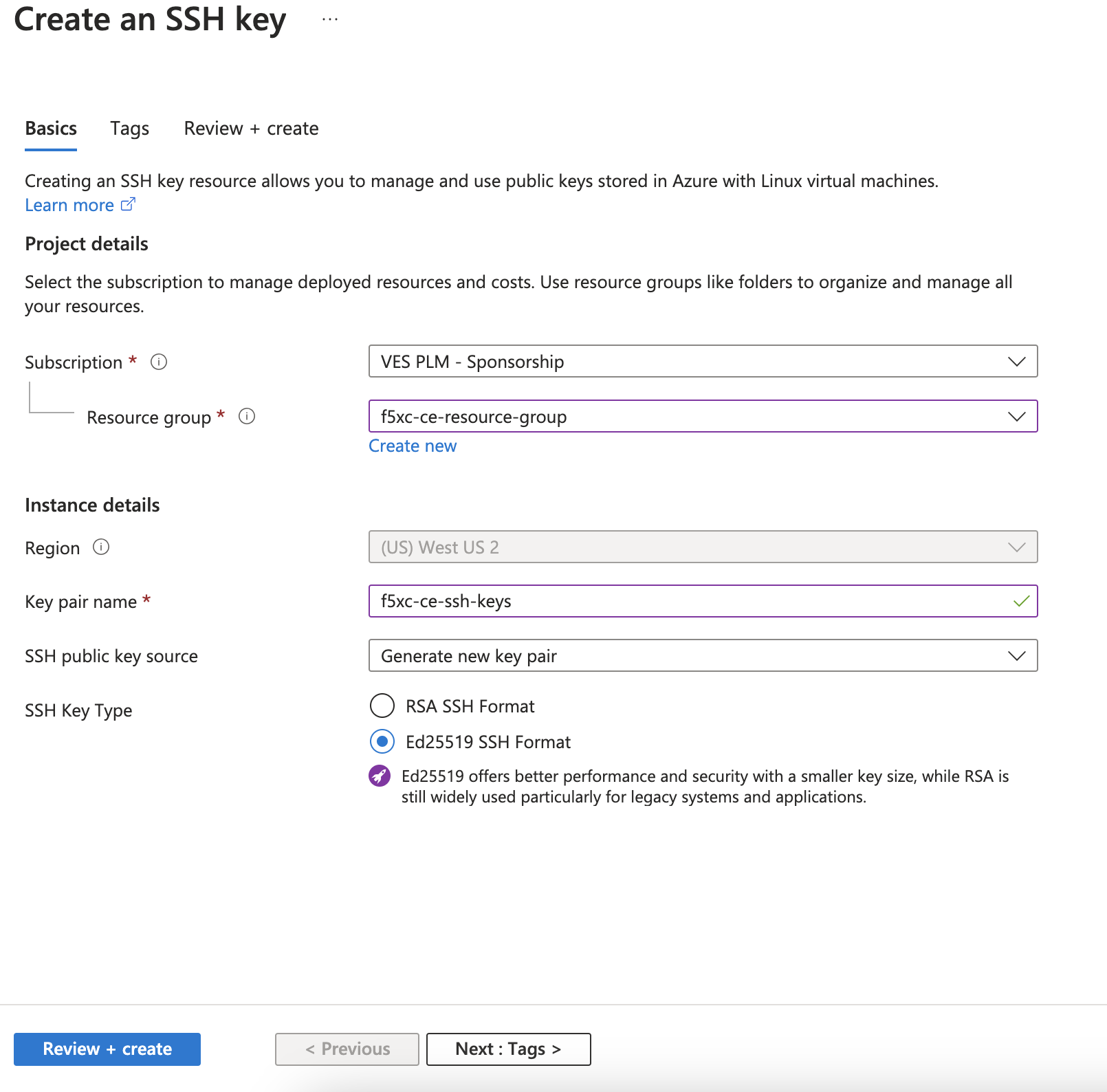
Figure: Create SSH Key Pairs
-
After successful validation, click Create.
-
Click Download private key and create resource to download the key pair locally to your machine since the pair is not saved in Azure. You need the key pair to log into the CE node.
Prepare VNet Resources
In this procedure, dual interface single-node and multi-node CE sites are being deployed. Therefore, you need two subnets: SLI (Site Local Inside) and SLO (Site Local Outside). Note that workload subnets are generally used but are not a requirement to deploy a CE Site.
Note: Azure subnets are not zonal constructs, so the same subnets can be used for deploying nodes in different availability zones for a multi-node Site.
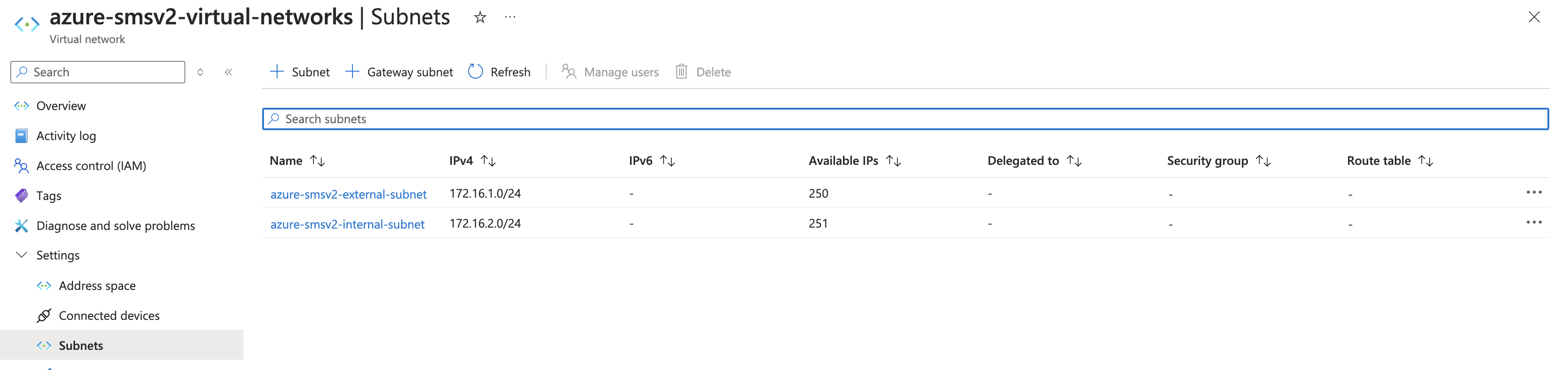
Figure: View Subnets
Create Public IP Address
In Azure Console, create a public IP address. You need to create one public IP address for each node that is being deployed for the CE site. In other words, for a single-node CE Site, you need to create one public IP address. For a CE Site with high availability (HA) enabled, you need to create three public IP addresses.
- Navigate to the Public IP addresses creation page and click Create.
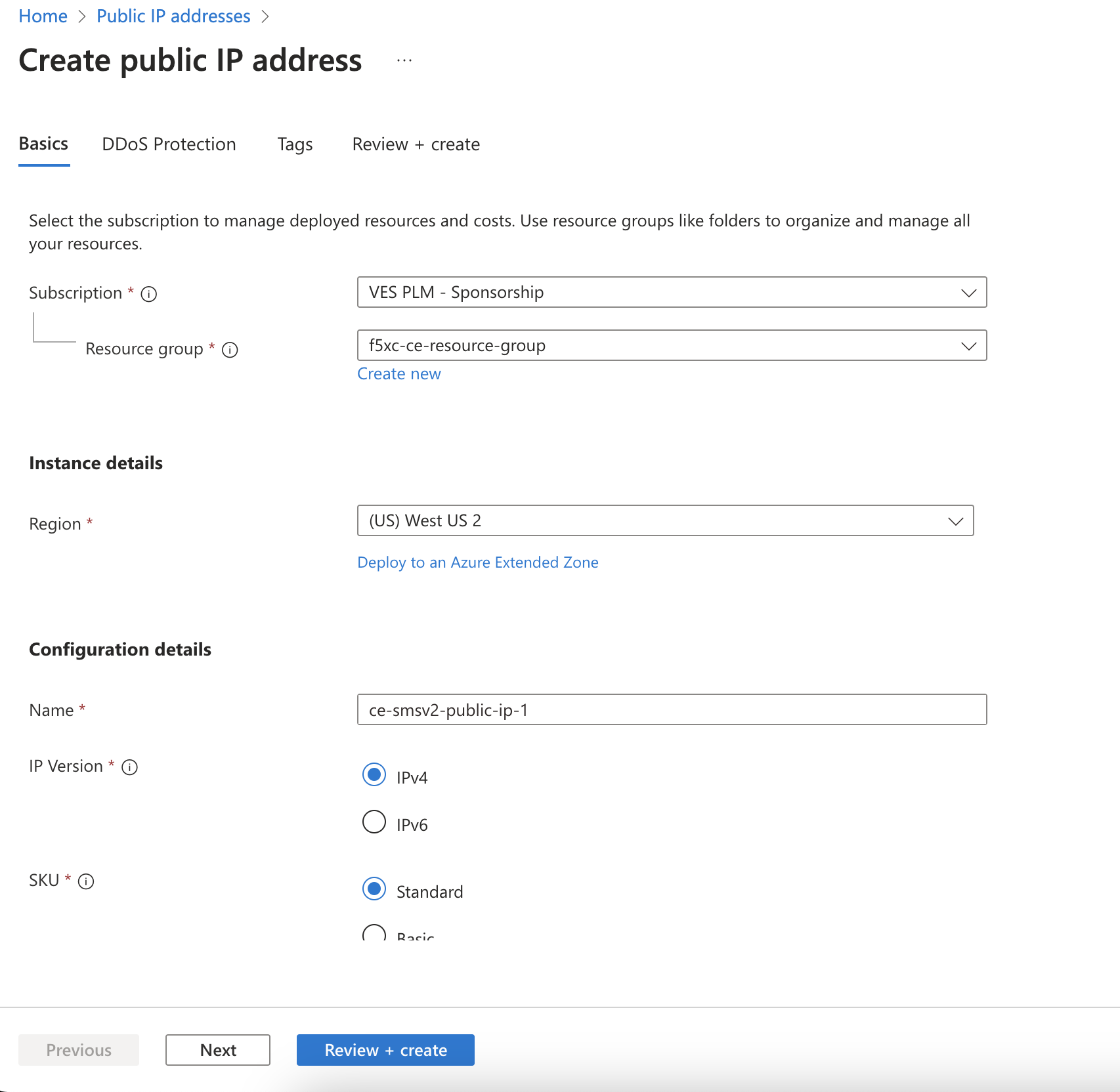
Figure: Create Public IP
-
Under Configuration details, in the Name field, enter a name for the public IP.
-
Leave the remaining options with their default values.
-
Click Review + create.
-
After validation passes, click Create.
-
For a multi-node Site, repeat the steps above to create public IP addresses for nodes two and three.
Generate Node Token
A one-time node token is required to register a CE Site node to the Distributed Cloud Console. A new token must be generated for every new node in a CE Site. A token is valid for 24 hours. Make sure that the CE node is deployed soon after the token is generated.
-
In Distributed Cloud Console, select the Multi-Cloud Network Connect workspace.
-
Navigate to Manage > Site Management > Secure Mesh Sites v2.
-
For your Site, click ... > Generate Node Token.
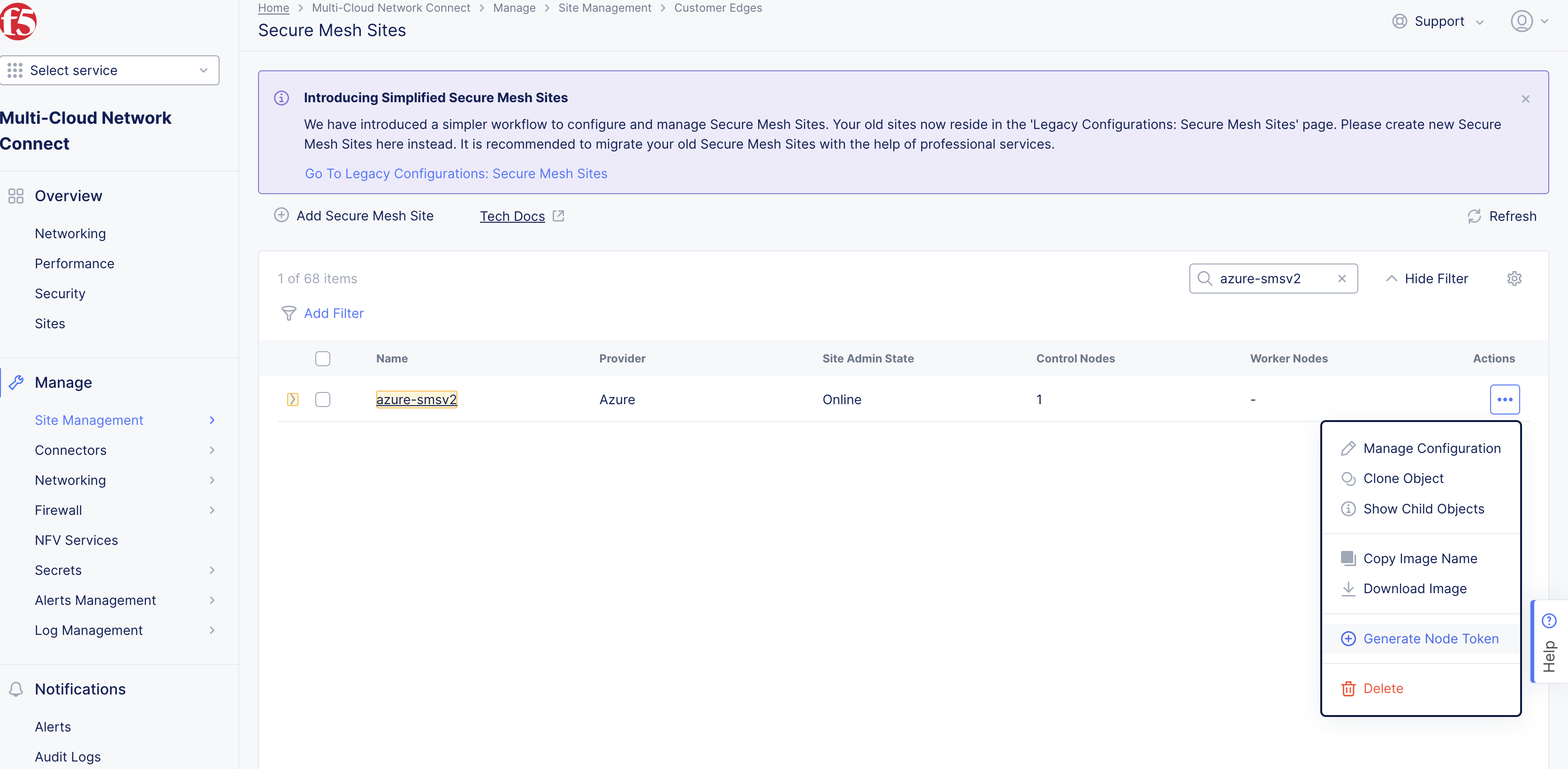
Figure: Node Token
-
Click Copy.
-
Save the value locally. This token is used later. The token value is hidden for security purposes.
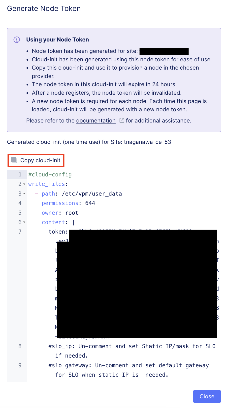
Figure: Copy Node Token
-
Click Close.
-
Generate one token per node you intend to deploy.
Create Azure Virtual Machine
You can use one of two methods to create the Azure VM. You can (1) deploy directly from Azure Marketplace, or (2) deploy using a downloaded image file. Each VM is a node in your Site.
This procedure uses Standard_D8_v4 as an example. To find your right size and requirements, refer to the Customer Edge Site Sizing Reference guide.
Important: The name of the VM should not have "." in it. For example, the hostname can be node-0 or node0, but it cannot be node.f5.com since it is not supported. Your node VM name must adhere to DNS-1035 label requirements. This means the name must consist of lower case alphanumeric characters or “-“, start with an alphabetic character, and end with an alphanumeric character.
If configuring a multi-node site, each node hostname must be unique.
Launch Node VM Instance from Azure Marketplace
This section guides you through the procedure to deploy directly from Azure Marketplace using a public image published by F5.
Step 1: Create new virtual machine.
-
In Distributed Cloud Console, select the Multi-Cloud Network Connect workspace.
-
Navigate to Manage > Site Management > Secure Mesh Sites v2.
-
For your Site, click ... > Launch Instance. This action opens the CE image listing on Azure Marketplace in a new browser tab.
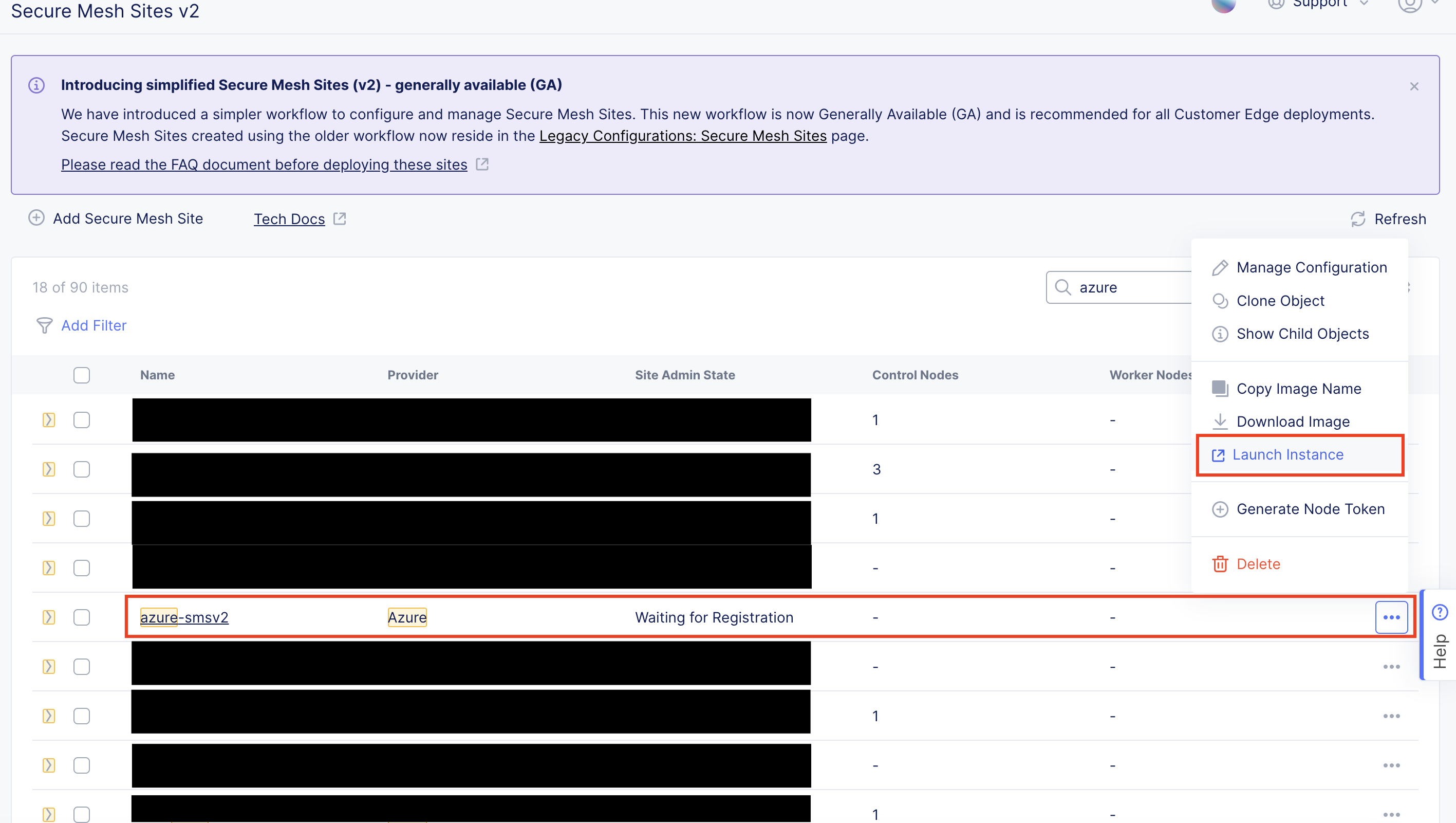
Figure: Launch VM
- Click Create to launch a new CE virtual machine.
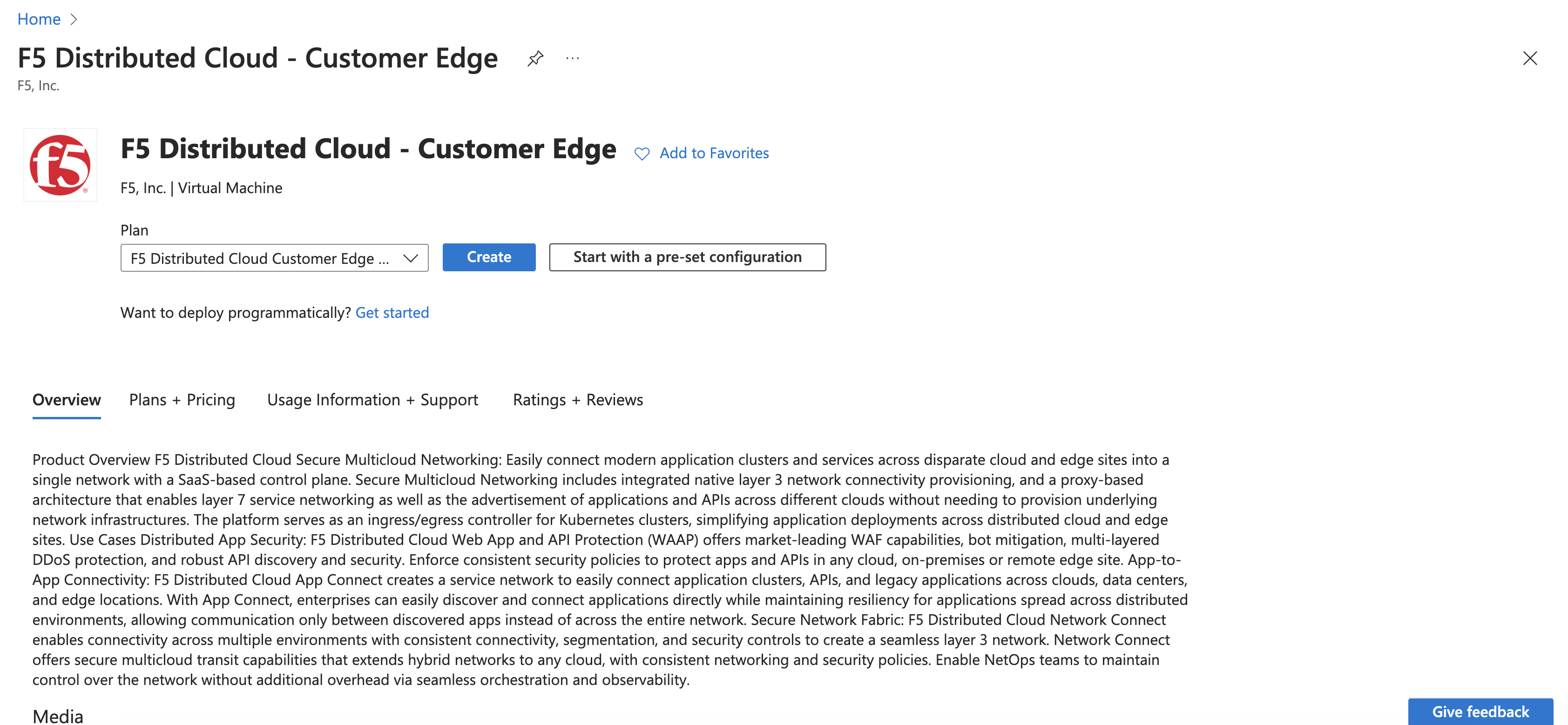
Figure: Create VM
Step 2: Configure new virtual machine.
-
Confirm the Subscription and Resource group options.
-
Enter a VM name.
-
Ensure the correct region and availability zone are selected.
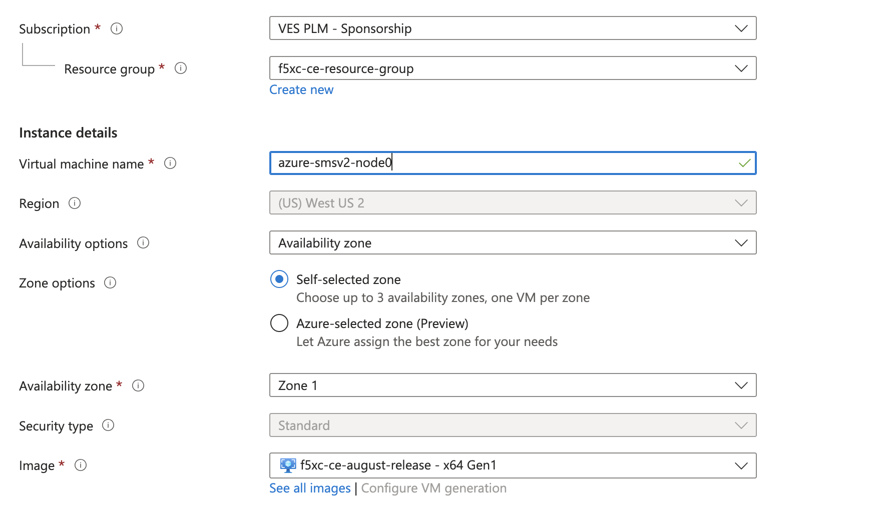
Figure: Configure VM
- From the Size menu, choose the instance type. This procedure uses Standard_D8_v4 as an example.
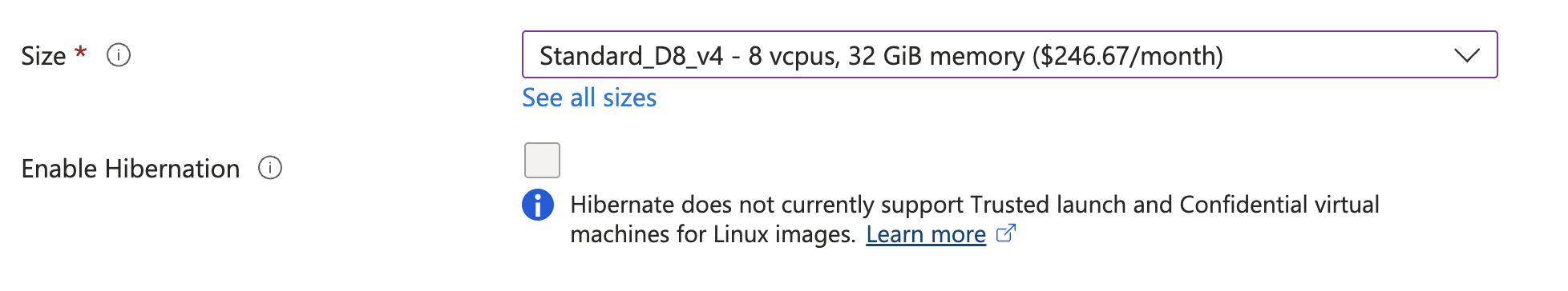
Figure: Configure VM Size
-
In the Username field, enter admin as the default user to SSH log into the CE instance.
-
From the SSH public key source menu, assign the previously created SSH key pair.
-
In the Key pair name, enter a name.
-
Click Next: Disks.
-
From the OS disk size menu, select 128 GiB (P10). The minimum disk requirement is 80 GB. However, for Azure, the 128 GB option is used instead as there is no 80 GB option available by default.
Step 3: Configure virtual machine networking.
-
Click Next: Networking.
-
Ensure the following parameters for network interface configuration:
- From the Virtual network menu, select the network.
- From the Subnet menu, select the external interface.
Important: You cannot create or assign the internal interface to the virtual machine in this step. It is added at a later step.
-
From the Public IP menu, select the IP address previously created.
-
For the NIC network security group option, select Advanced. This option is needed so that you can select the network security group.
-
From the Configure network security group menu, select the security group previously created.
-
Select the Delete public IP and NIC when VM is deleted option.
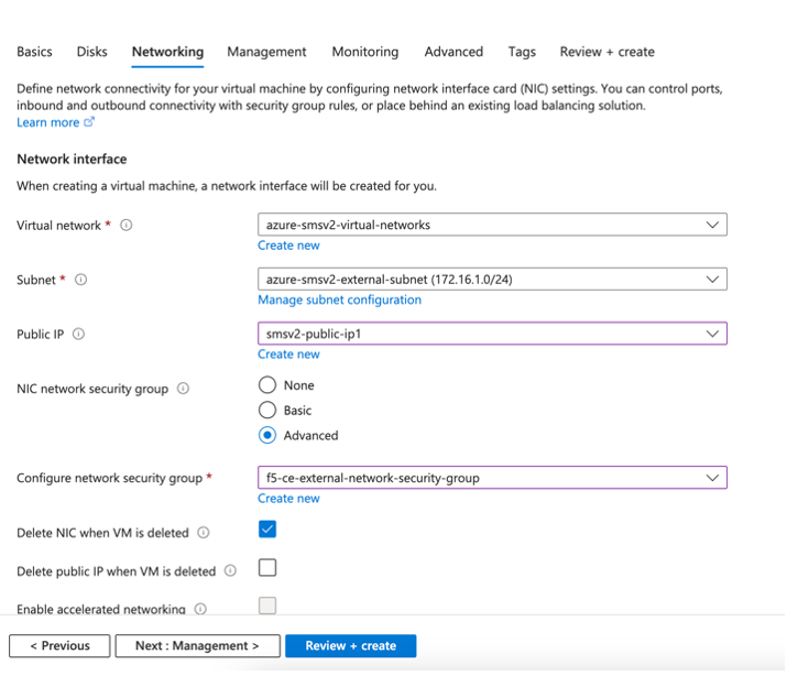
Figure: Configure VM Networking
Step 4: Configure advanced settings.
-
Click the Advanced tab to skip the management and monitoring configuration.
-
In the Custom data field, paste the cloud-init information (which includes the node token) copied from the Generate Node Token section.
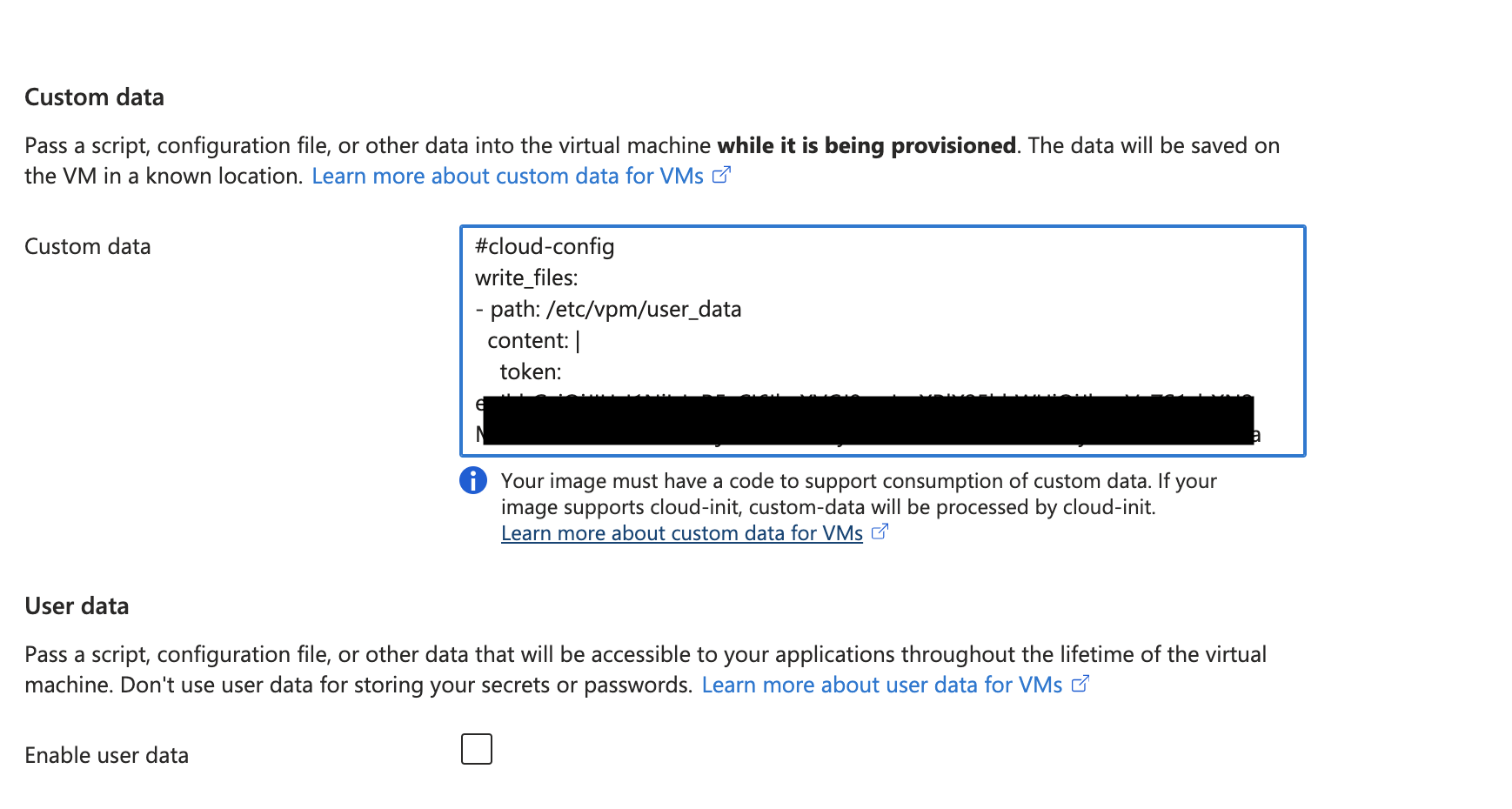
Figure: Configure VM User Data
Step 5: Complete creation.
-
Click Review + create.
-
After the validation process completes successfully, click Create.
Terraform Example for Azure VM Creation Using Azure Marketplace Image
You have the option to automate the deployment of the latest available Azure Marketplace image using the Azure-provided Terraform.
- Obtain the specific plan using the following command with your choice of region (any region can be used):
latestPlan=az vm image list-skus --publisher f5-networks --offer f5xc_customer_edge --location westus --query "[].name" -o tsv | grep "crt-" | sort -rV | head -1
- Using the latestPlan command output above, add the Azure VM Terraform attributes:
      plan {
            name      = <latest plan>
            publisher = "f5-networks"
            product   = "f5xc_customer_edge"
      }

      source_image_reference {
            publisher = "f5-networks"
            offer     = "f5xc_customer_edge"
            sku       = <latest plan>
            version   = "latest"
      }
Launch Node VM Instance from Downloaded File
If you want to create VM node using a downloaded file, follow the instructions below.
Important: Starting March 2026 release of F5 Distributed Cloud, the Actions > Download Image and Actions > Copy Image Name options were removed for Azure provider from F5 Distributed Cloud Console. If you need to download the latest image, use this download link.
Step 1: Download and unzip file.
-
Download the latest image. The file downloads as a
f5xc-ce-crt-<version>.vhd.gzfile onto your local machine. -
Ensure you validate the integrity of the file using the MD5 checksum 013b2dbd64190a1a066c292ed6d2e1b3.
-
Unzip the
f5xc-ce-crt-<version>.vhd.gzfile.
Step 2: Upload file to Azure portal.
-
In Azure portal, navigate to the Storage Accounts creation page.
-
Click Create.
-
Select your resource group and provide a name for your storage account. Leave all other default settings.
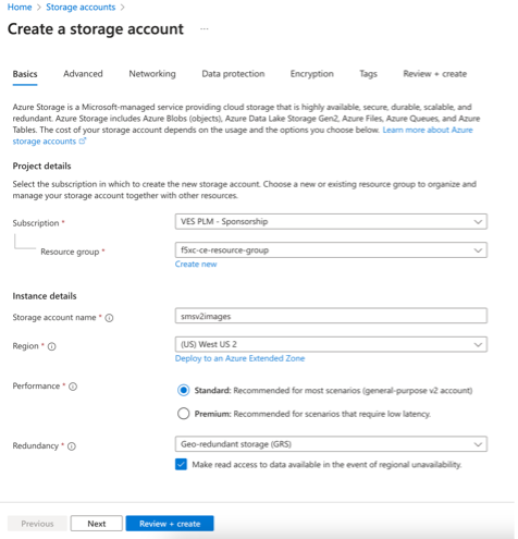
Figure: Upload Node Image
-
Click Review + create.
-
After validation passes, click Create.
-
After the storage account is created, click Upload to upload VHD file. Select the file from your local device.
-
If the container does not exist, create the container as f5xc-azure-ce. Upload the VHD file to the container.
-
Under Advanced Options, select blob type as Page Blob.
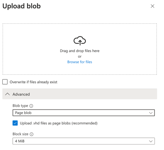
Figure: Page Blob
- After the VHD file upload is complete, confirm the file appears as shown below.
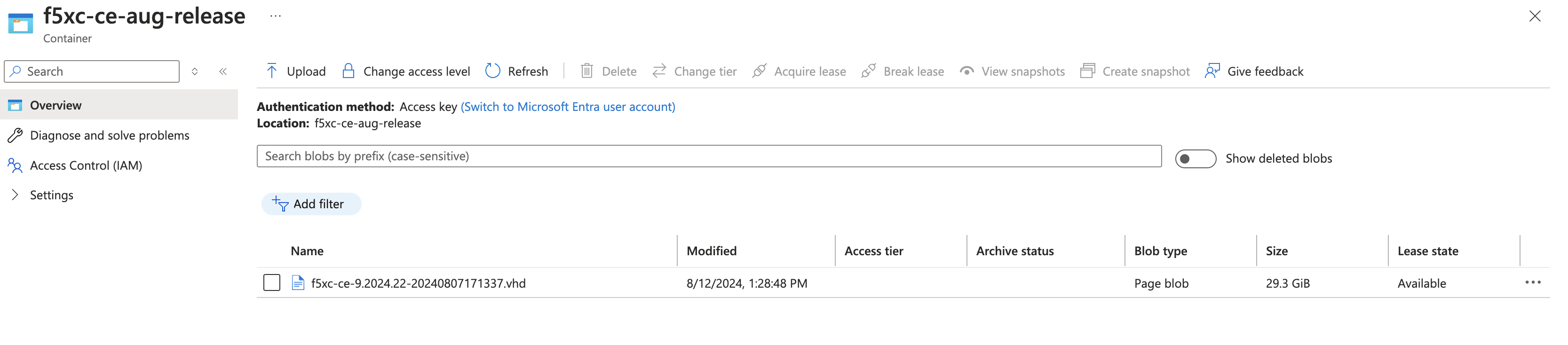
Figure: Confirm Upload
Step 3: Create image using the VHD file uploaded.
-
Navigate to the Images creation page and click Create.
-
Select your resource group and provide a name for your image.
-
Select the OS type as Linux.
-
Browse to the VHD image just uploaded to provide the path to the storage blob location.
-
Select Account type as Standard SSD.
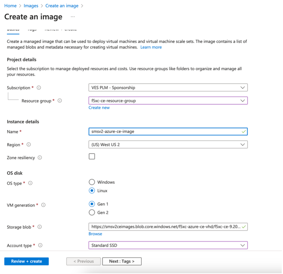
Figure: Create Image Parameters
-
Click Review + create.
-
After the validation passes, click Create.
Verify CE Site Registration
After you deploy your nodes, they automatically register as a CE Site in Distributed Cloud Console. The registration process is not instantaneous. In Console, the status changes from Waiting for Registration to Provisioning to Online. Wait a few minutes for the registration process to begin after completing the preceding sections.
-
In Distributed Cloud Console, navigate to Multi-Cloud Network Connect > Overview > Infrastructure > Sites.
-
Select your CE Site. The Dashboard tab should clearly show that the CE Site has registered successfully with the System Health of 100% as well as Data Plane/Control Plane both Up.
Note: For more information on the CE Site registration process, see the Customer Edge Registration and Upgrade Reference guide.
Manage Network Interfaces (Optional)
After your CE Site registers successfully, you might want to add additional network interfaces to meet your requirements. Ensure that you connect another network interface to the node VM.
Important: Adding or removing network interfaces causes the data plane services on the CE node to restart. Therefore, F5 strongly recommends that you perform this operation during maintenance windows. As data plane services restart, traffic drops are expected, as well as tunnels to F5 Distributed Cloud REs going down.
All CE nodes in a given CE site should have the same number of network interfaces attached. CE nodes with non-homogenous interfaces within a CE Site might cause issues.
Each node in the CE site should have interfaces with the same VRFs assigned. For example: If a CE Site has three nodes, with each node having two interfaces - the first interface on each node is auto-configured to be in the SLO VRF (to connect to F5 Distributed Cloud). If the second interface on node-1 is in the SLI VRF, then the second interface on node-2 and node-3 must also be in the SLI VRF.
When new interfaces are added, they are auto-discovered. You can configure the interface (for example: place the interface in the appropriate VRF) from the CE Site configuration.
The first interface of the CE nodes should not be removed or modified.
After you configure the SLO interface with a static IP address, DHCP will still be displayed in the Console. However, your static IP configuration is well taken into account. Also, remember that you cannot modify SLO parameters once the node is registered and deployed.
Add New Interface
Step 1: Stop VM.
In Azure portal, select your VM and click Stop.
Step 2: Create new interface.
- After the VM stops, click Network settings. Then click Attach network interface.
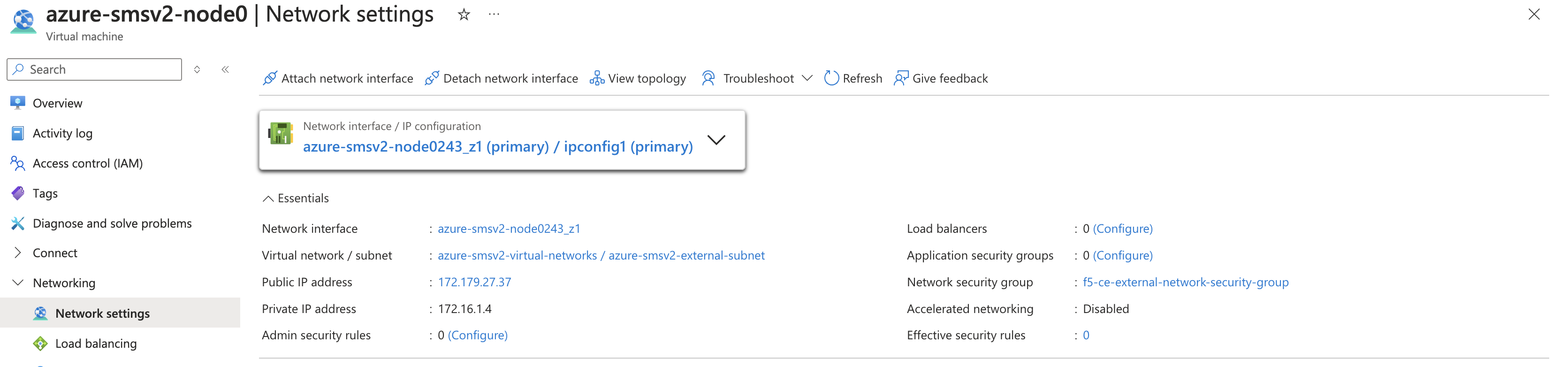
Figure: Add Second Interface
-
Click Create and attach the network interface.
-
Select the resource group previously created for this VM.
-
In the Name field, enter a new name for this second interface.
-
In the Subnet field, select the internal subnet created earlier. Make sure to reference that this is an internal interface since the external interface was previously created.
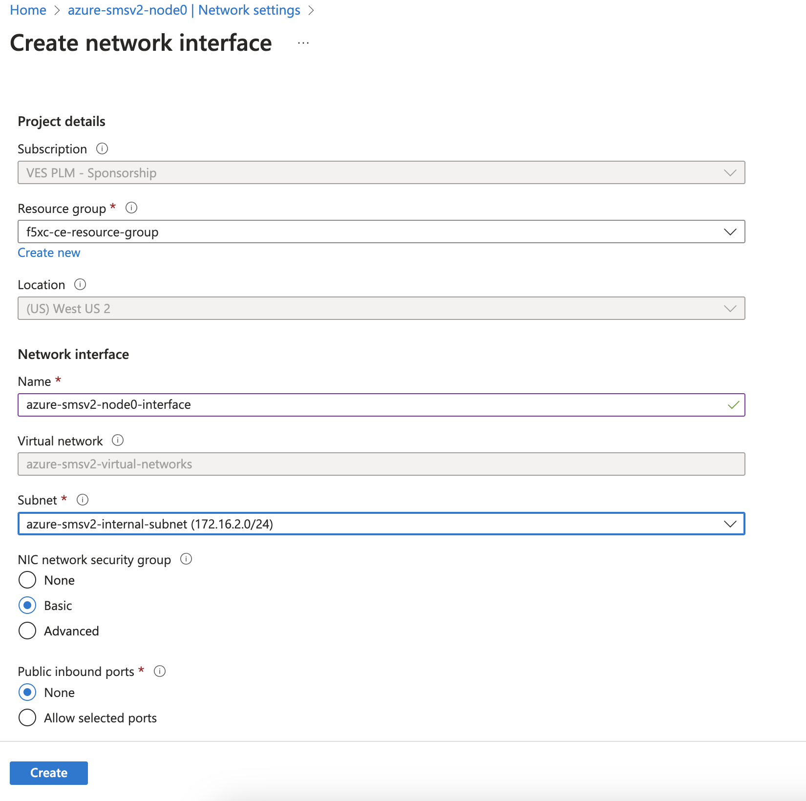
Figure: Add Second Interface
- Click Create.
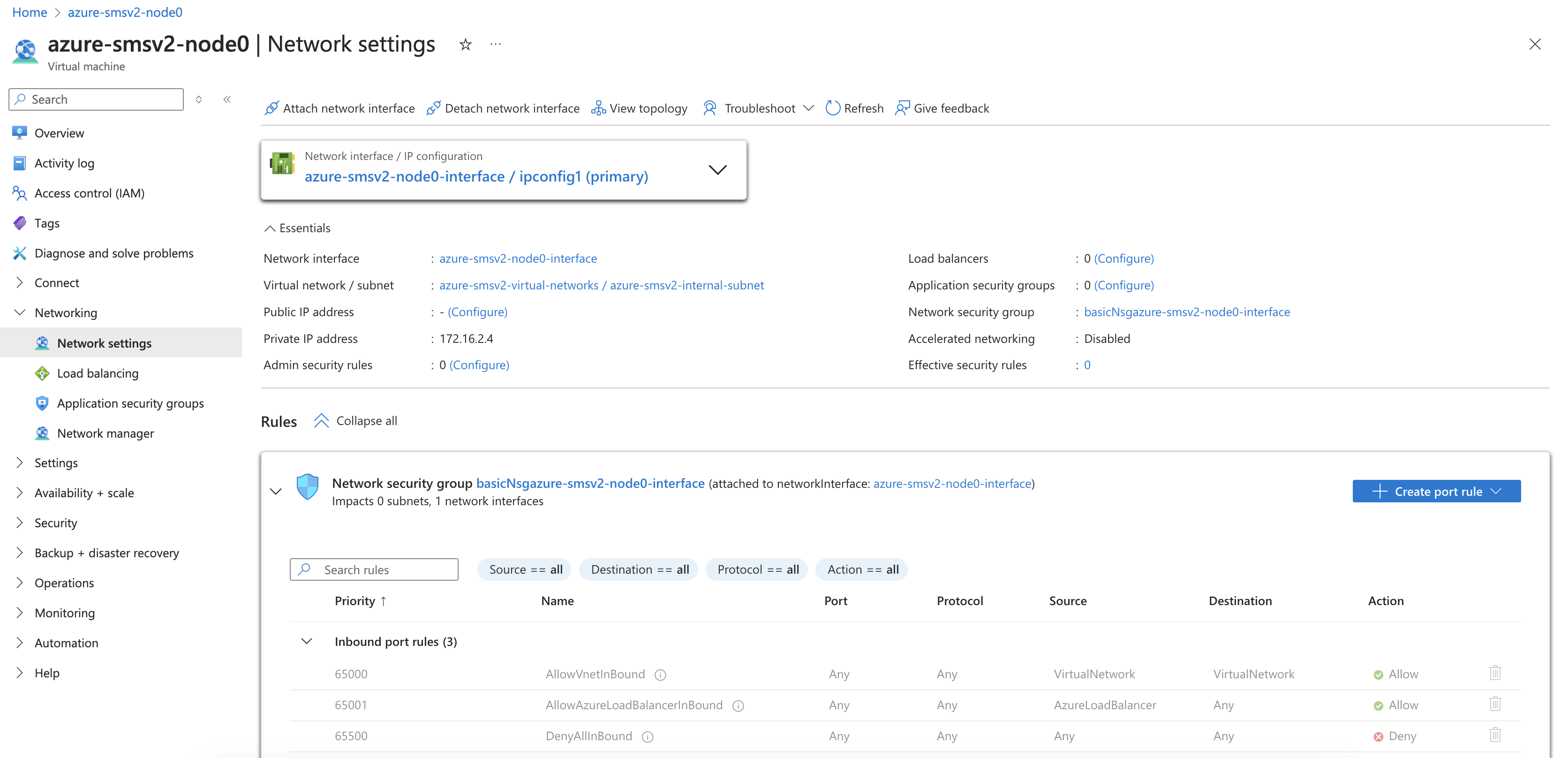
Figure: Second Interface
Step 3: Start VM.
-
After the second interface is attached to your VM, start the VM.
-
Use the steps above to create and attach additional interfaces to this VM.
Step 4: Configure static IP address.
-
After the Site is back online, click Manage Configuration. Then, in the wizard, click Edit Configuration.
-
Under the Interfaces subsection, click the pencil icon under Actions to edit. In the current release, additional interfaces, including SLI interface, need to be configured with a static IP address which in this case must be same as that allocated by Azure.
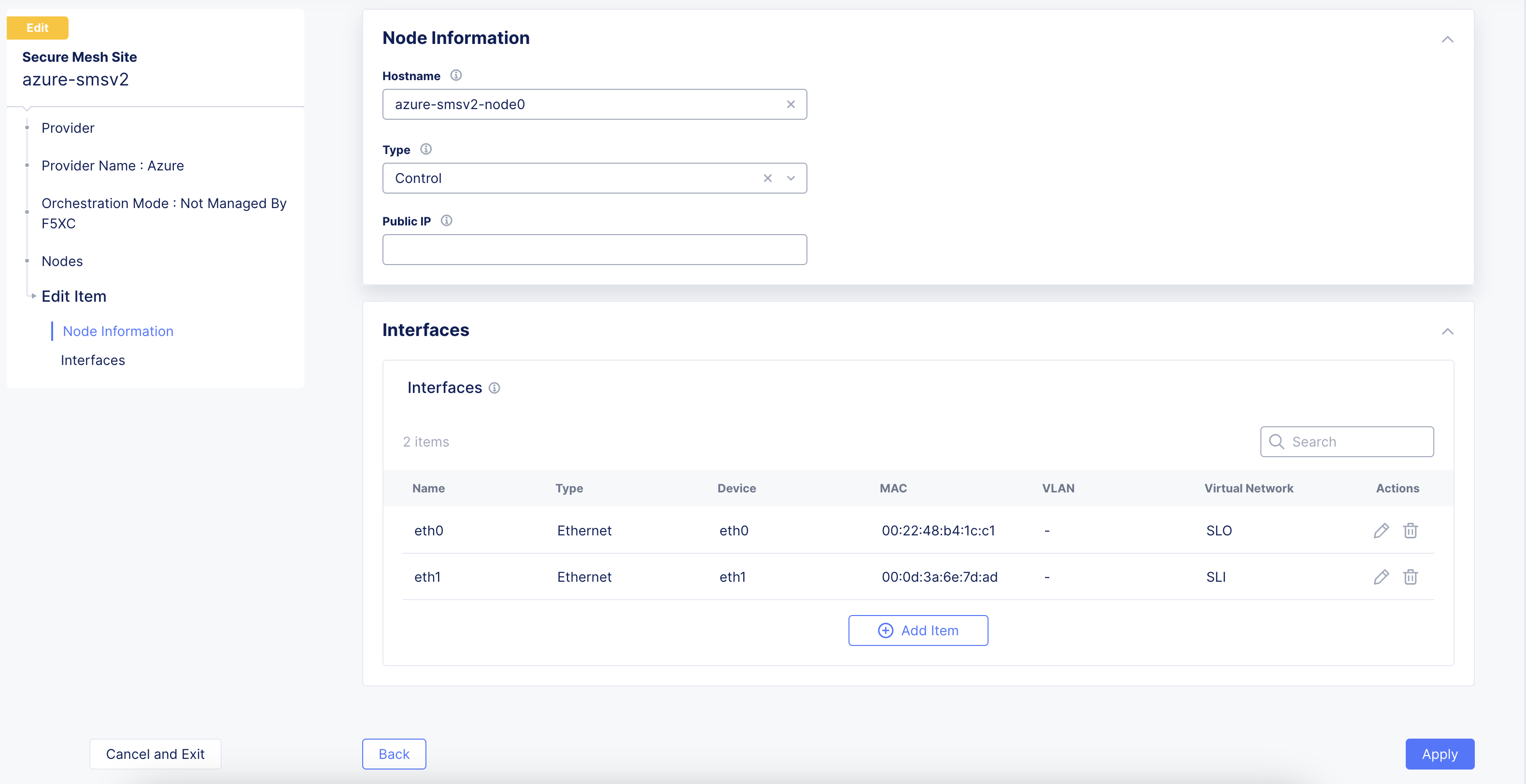
Figure: Edit Interface
-
Select Static IP as the IPv4 Interface Address Method.
-
Enter the IPv4 address with prefix length. This must be same as that allocated by Azure.
-
Click Apply.
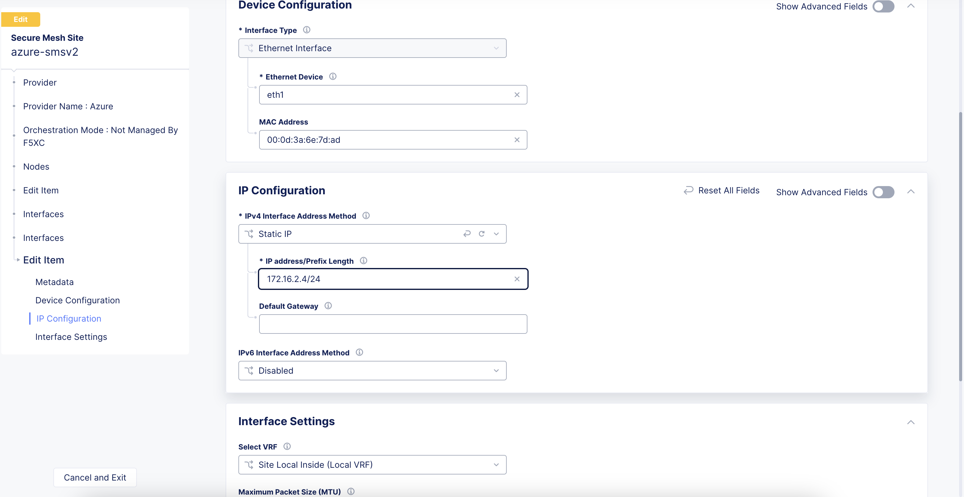
Figure: Edit Interface
- Click Save Secure Mesh Site.
Step 5: Verify changes.
Visually verify the same information from the Distributed Cloud Console by navigating to Multi-Cloud Network Connect > Overview > Infrastructure > Sites and selecting your Site name. Select the Infrastructure tab and view the Interfaces table.
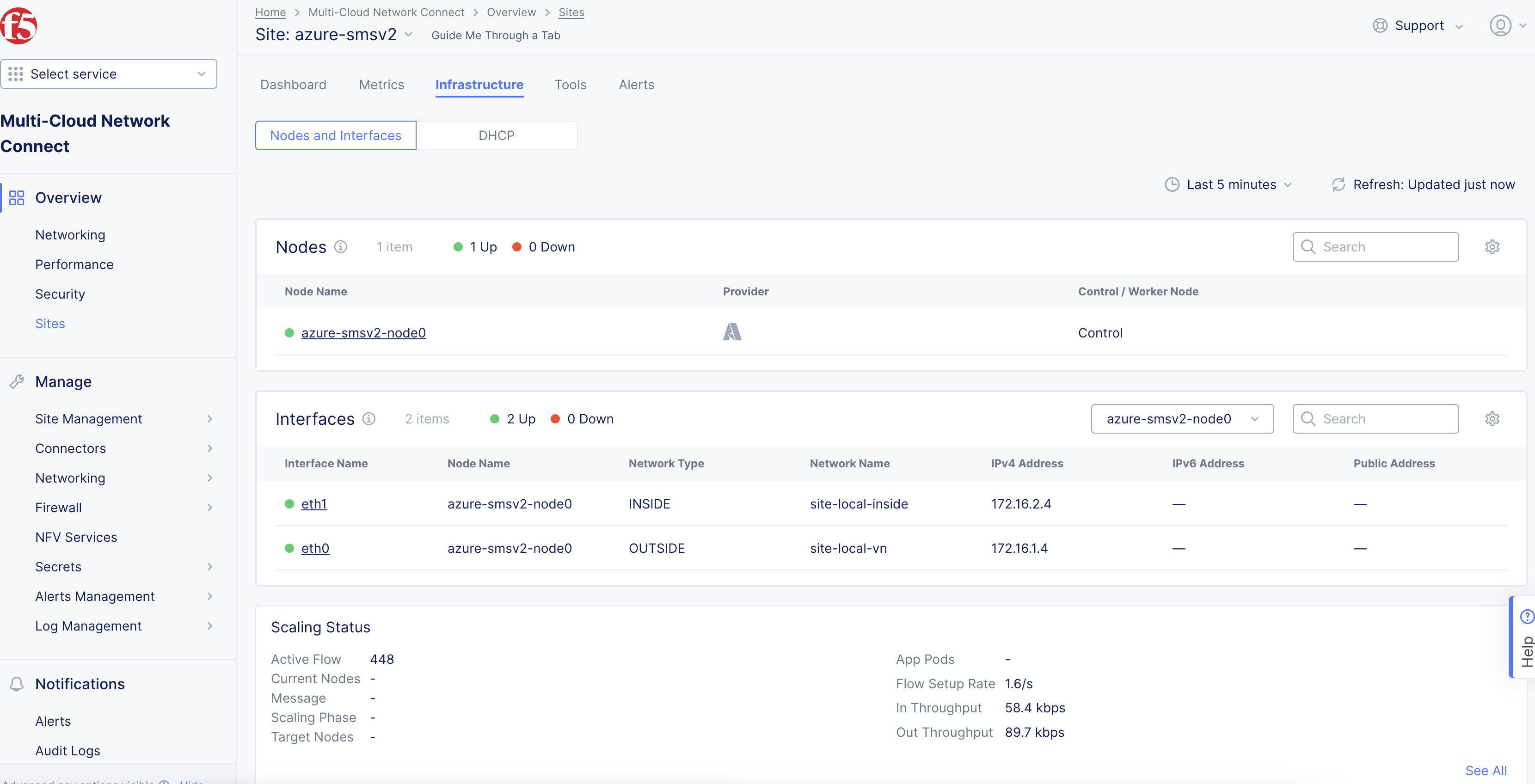
Figure: Verify Interface
Enable Additional Settings for Application Traffic Flow
For services, like network connectivity, application connectivity, and delivery to work correctly, you need to enable additional settings for Azure CE nodes. You need to enable the IP forwarding setting on each NIC of your Azure CE node.
-
In Azure portal, navigate to Network settings for your CE node.
-
Click the NIC for the CE node.
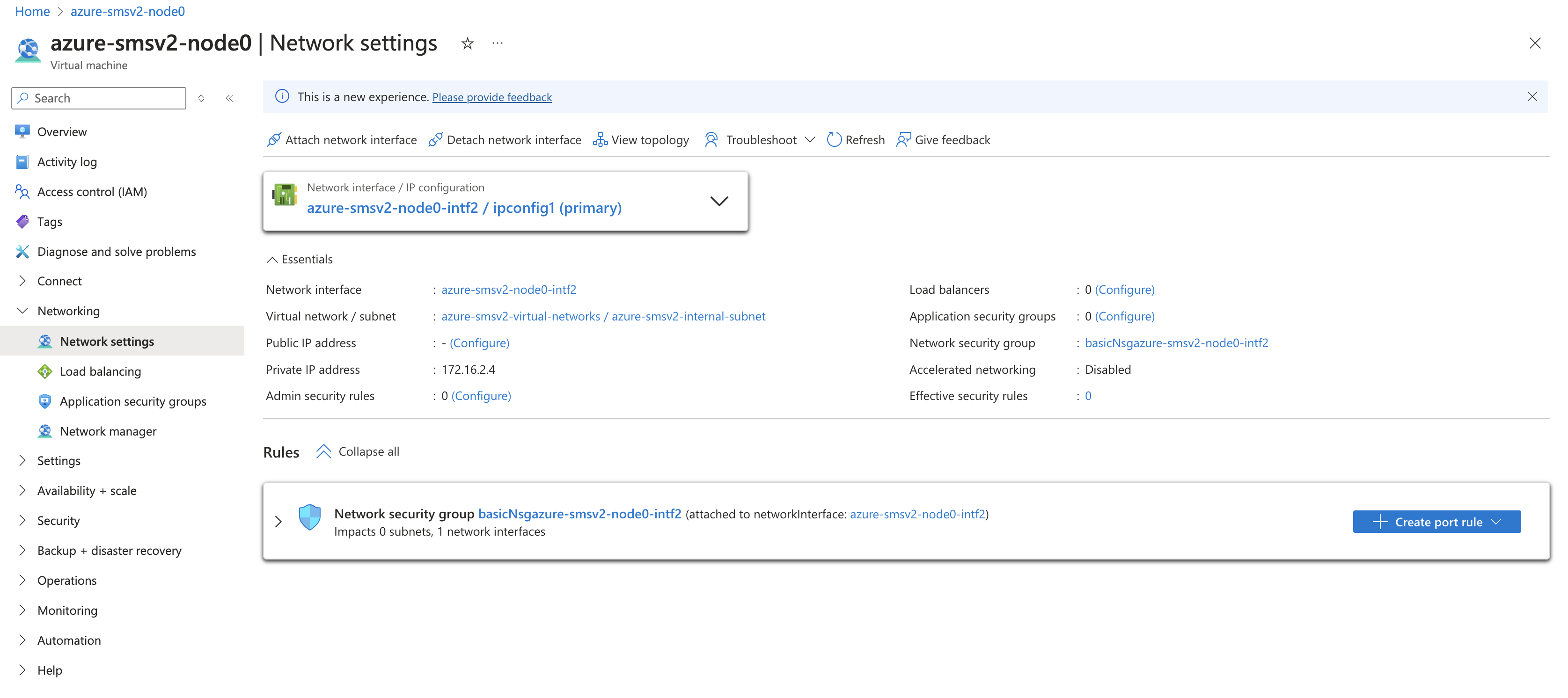
Figure: Node NIC Settings
- Select Settings > IP configurations and enable the Enable IP forwarding checkbox.
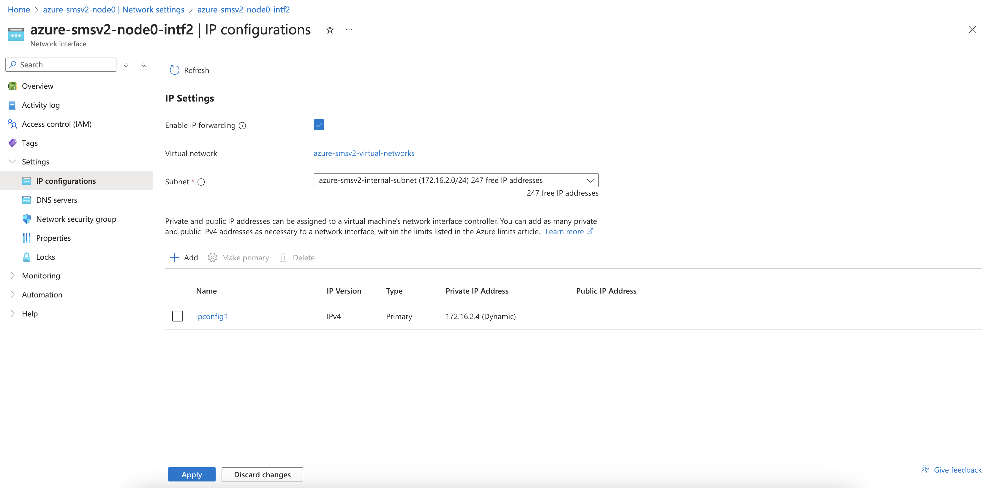
Figure: Enable IP Forwarding
Day 2 Operations
- To monitor your Site, see the Monitor Site guide.
- To manage your Site software and OS updates, see the Manage Site guide.
- For troubleshooting issues, see the Troubleshooting Guide for Secure Mesh Site v2 Deployment guide. It provides step-by-step instructions to debug and resolve the issues that may arise due to registration and provisioning errors.
- For the latest on Distributed Cloud Services releases, see Changelogs.
- To view the various types of events generated, see the Events Reference guide.
Related Guides
To create a load balancer on the CE Site, see the HTTP Load Balancer or the TCP Load Balancer guides.
Concepts
On this page:
- Objective
- Planning
- General Prerequisites
- Configuration Overview
- Procedure
- Create Site Object
- Create Network Security Group
- Create SSH Key Pair
- Prepare VNet Resources
- Create Public IP Address
- Generate Node Token
- Create Azure Virtual Machine
- Launch Node VM Instance from Azure Marketplace
- Terraform Example for Azure VM Creation Using Azure Marketplace Image
- Launch Node VM Instance from Downloaded File
- Verify CE Site Registration
- Manage Network Interfaces (Optional)
- Add New Interface
- Enable Additional Settings for Application Traffic Flow
- Day 2 Operations
- Related Guides
- Concepts