Create Secure Mesh Site
Objective
Important: This is a legacy workflow for deploying Customer Edge (CE) sites and is not recommended to use. A new workflow for deploying Customer Edge (CE) sites has been introduced and is now Generally Available (GA). F5 recommends you use the new Secure Mesh Site (v2) workflow for all your Customer Edge deployments. You can find this workflow here.
This document provides instructions on how to create an F5® Distributed Cloud single-node or multi-node F5 Distributed Cloud Secure Mesh Site. A Secure Mesh Site can be used to register and manage a site deployed on-premises (on VMware, KVM, or baremetal) or manual site deployments on public clouds (AWS, Azure, and GCP) using the cloud provider's console or using the cloud provider's Terraform.
A Secure Mesh Site is a Distributed Cloud Customer Edge (CE) engineered specifically to provide ease for you to create sites with any F5® Distributed Cloud Mesh certified hardware.
Prerequisites
-
An F5 Distributed Cloud Account. If you do not have an account, see Getting Started with Console.
-
One or more devices or VMs consisting of interfaces with Internet reachability for Site installation.
-
Resources required per node: Minimum 8 vCPUs, 32 GB RAM, and 80 GB disk storage. For a full listing of the resources required, see the Customer Edge Site Sizing Reference guide. All the nodes in a given CE Site should have the same resources regarding the compute, memory, and disk storage. When deploying in cloud environments, these nodes should use the same instance flavor.
-
Allow traffic from and to the Distributed Cloud public IP addresses to your network and allowlist related domain names. See F5 Customer Edge IP Address and Domain Reference for Firewall or Proxy Settings guide for the list of IP addresses and domain names.
-
Internet Control Message Protocol (ICMP) needs to be opened between the CE nodes on the Site Local Outside (SLO) interfaces. This is needed to ensure intra-cluster communication checks.
Important: After you deploy the CE Site, the IP address for the SLO interface cannot be changed. Also, the MAC address cannot be changed.
Create Site Token
Create a site token or use an existing token. If you are configuring a multi-node site, use the same token for all nodes.
Step 1: Navigate to site tokens page.
-
Log into F5® Distributed Cloud Console.
-
Click
Multi-Cloud Network Connect.
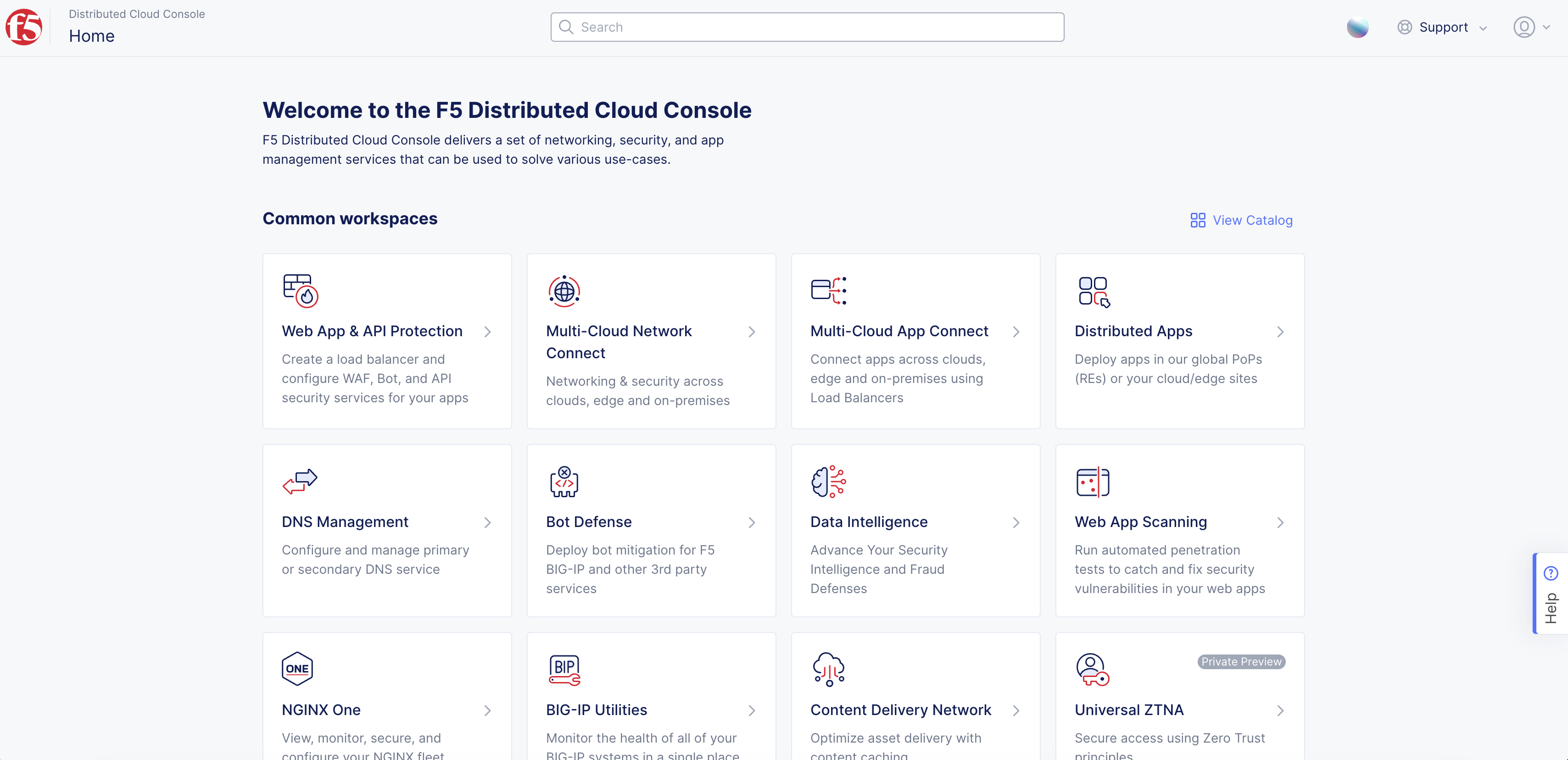
Figure: Console Homepage
-
Select
Manage>Site Management>Site Tokens. -
Click
Add Site Tokento create a new token.
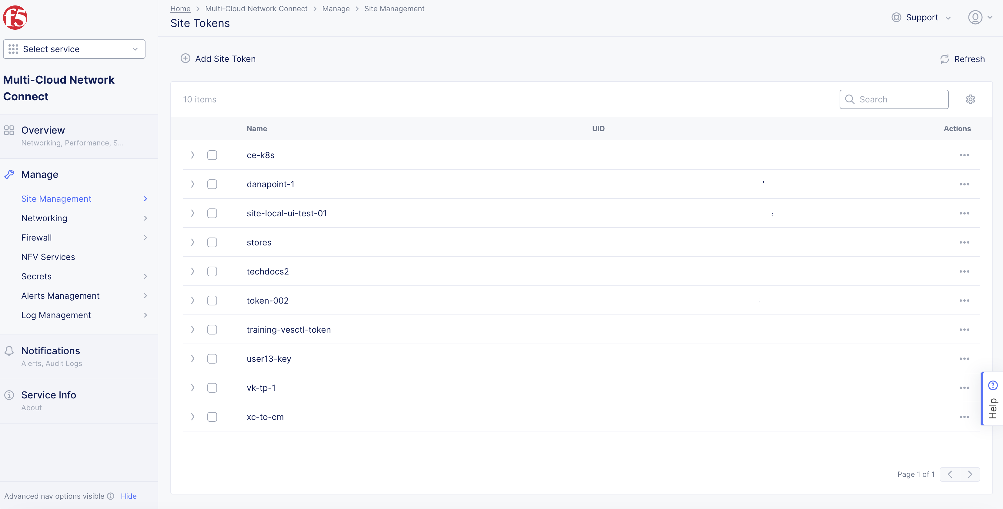
Figure: Site Tokens
Step 2: Generate a new site token.
-
In the
Namefield, enter the token name. -
In the
Descriptionfield, enter a description for the token. -
Click
Add Secure Mesh Site.
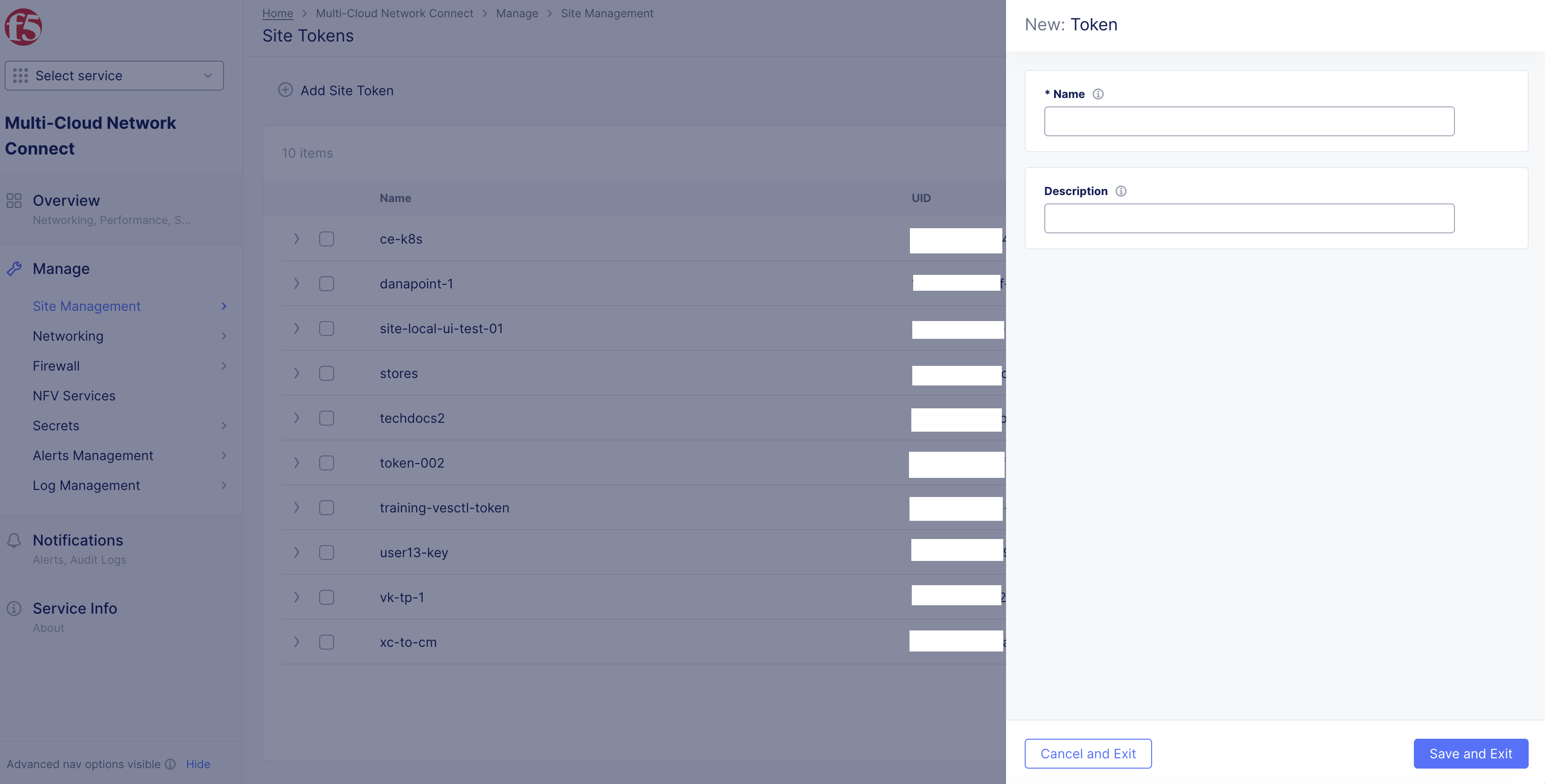
Figure: Site Token Form
Step 3: Note down the new token.
-
Find the token previously created or choose an existing token from the list of tokens displayed.
-
Click
>to expand the token details in JSON format and note down the value of theuidfield.
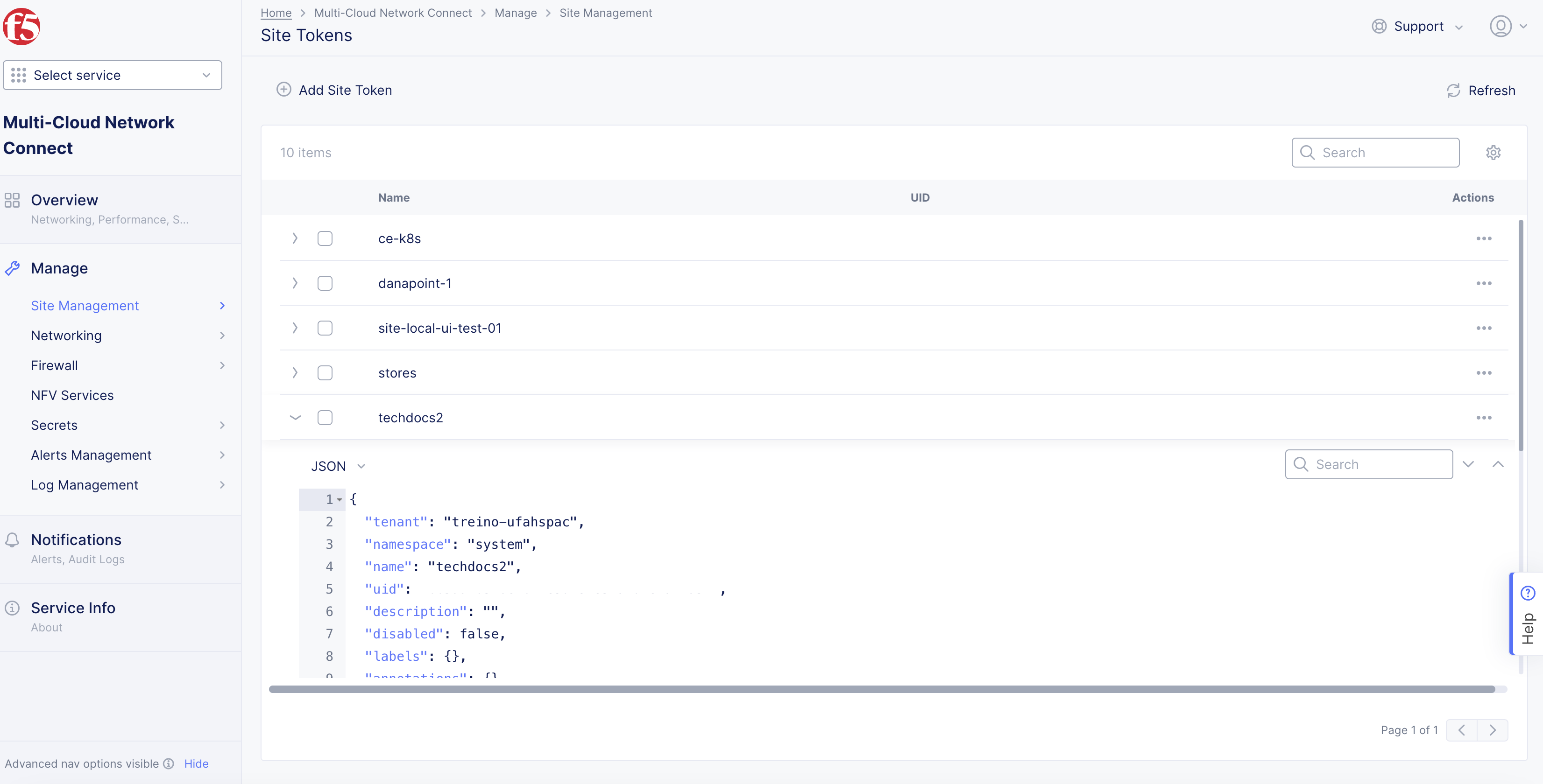
Figure: UID Field
Create Secure Mesh Site Object
Log into F5 Distributed Cloud Console and perform the following steps to create a single-node or a three-node secure mesh site:
Create Three-Node Secure Mesh Site
Step 1: Start creating Secure Mesh Site object.
-
In
Multi-Cloud Network Connectworkspace, navigate toManage>Site Management>Secure Mesh Sites. -
Select
Add Secure Mesh Siteto open the Secure Mesh Site configuration form.
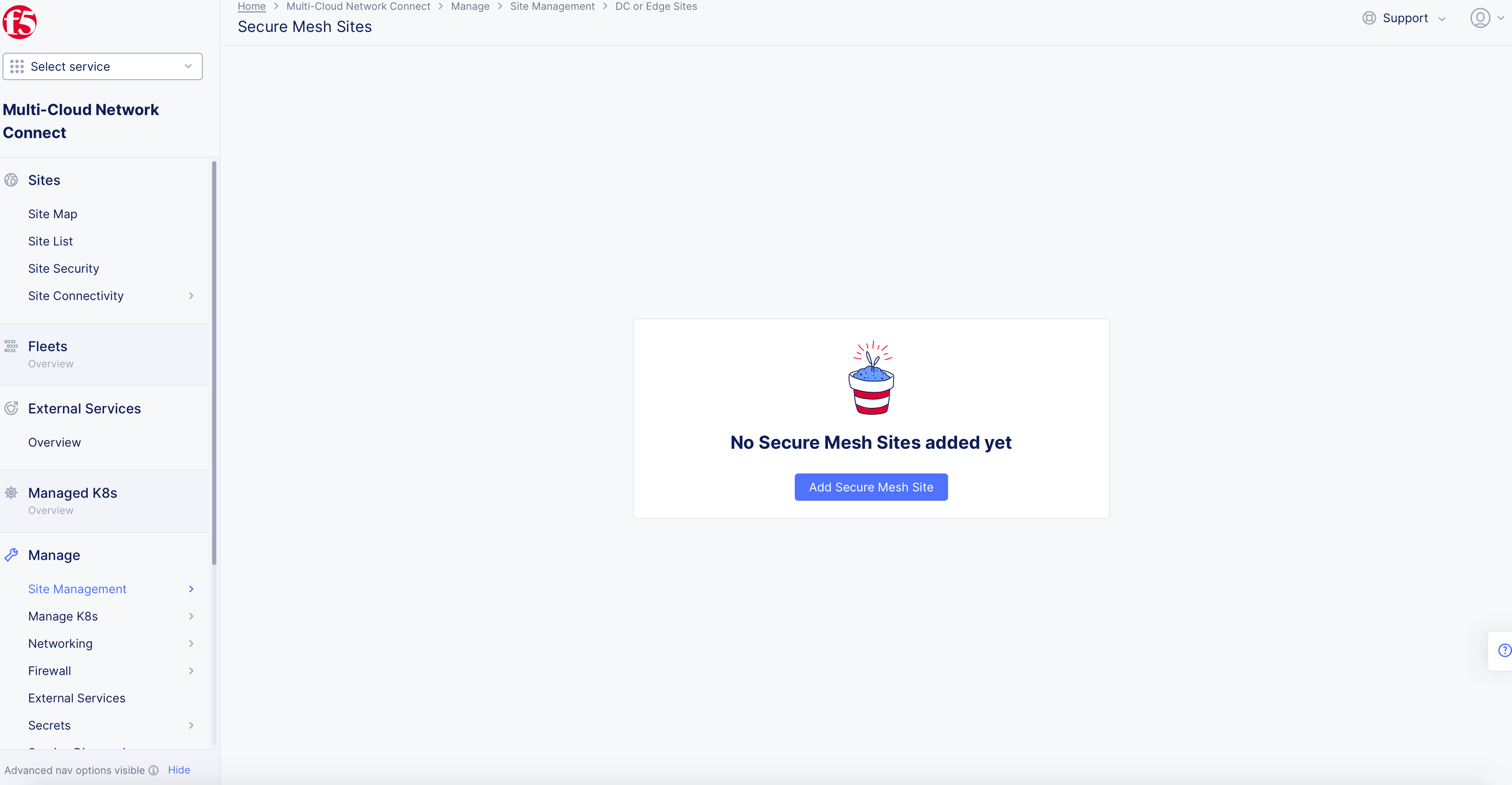
Figure: Navigate to Secure Mesh Site Configuration
-
Enter a name in the
Metadatasection for your Secure Mesh Site object. -
Optionally, select labels and add a description.
Step 2: Set the fields for basic configuration.
-
From the
Generic Server Certified Hardwaremenu, select an option. Theisv-8000-series-voltmeshis selected by default. If theGeneric Server Certified Hardwareis not listed in the drop-down menu, type in the name for your deployment. This may be needed if you are manually deploying a site in the public cloud using the ClickOps method. -
Enter the names of the master nodes in the
Master Nodesfield. SelectAdd Itemto add the second and third nodes.
Important: The name of the VM should not have "." in it. For example, the hostname can be node-0 or node0, but it cannot be node.f5.com since it is not supported. Your node VM name must adhere to DNS-1035 label requirements. This means the name must consist of lower case alphanumeric characters or “-“, start with an alphabetic character, and end with an alphanumeric character.
If configuring a multi-node Site, each node hostname must be unique.
-
Enter the public IP in the
Public IPfield for the master nodes. The IP addresses are only used when a site is part of a Site Mesh Group, and you have selected theSite Mesh Group Connection Via Public Ipoption for theSite Mesh Group Connection Typefield as shown in Step 4.6. You can leave this blank if your site nodes do not have a public IP address. -
Optionally, enter the names of worker nodes in the
Worker Nodesfield. SelectAdd Itemto add more than one node.
Important: The name of the VM should not have "." in it. For example, the hostname can be node-0 or node0, but it cannot be node.f5.com since it is not supported. Your node VM name must adhere to DNS-1035 label requirements. This means the name must consist of lower case alphanumeric characters or “-“, start with an alphabetic character, and end with an alphanumeric character.
If configuring a multi-node Site, each node hostname must be unique.
-
Optionally, enter the following fields:
-
Geographical Address: This derives geographical coordinates.
-
Coordinates: Latitude and longitude.
-
Important: F5 recommends that you enter the coordinates so that the CE connects to the geographically closest REs.
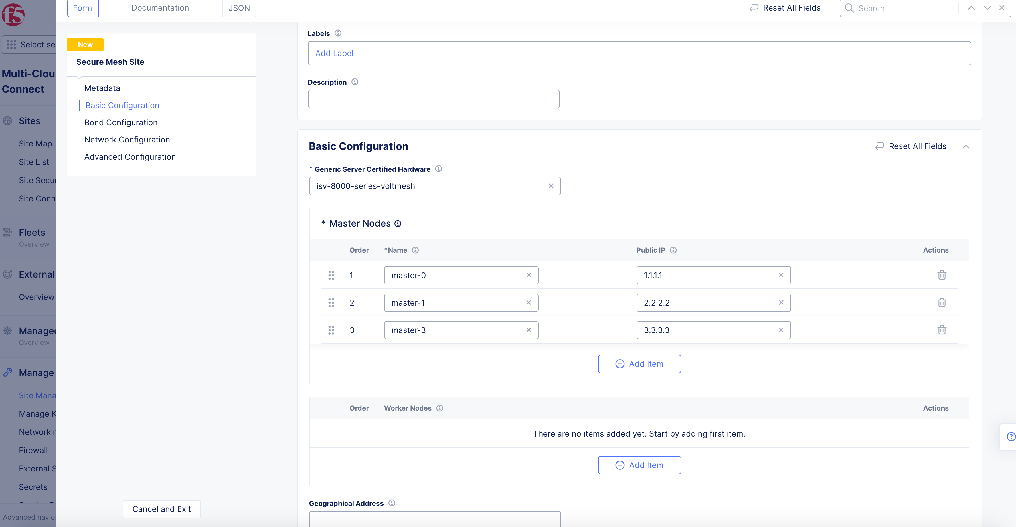
Figure: Secure Mesh Site Basic Configuration Section
Step 3: Optionally, configure bond interfaces.
In the Bond Configuration section, perform the following:
-
From the
Select Bond Configurationmenu, selectConfigure Bond Interfaces. -
Select
Configureto open bond interface configuration page. -
Select
Add Itemunder theBond Devices Listfield. -
Select on the
Bond Device Namefield and selectSee Common Values. You can also type a custom name and clickAdd Itemto set the device name while also adding it to the existing options. -
Select on the
Member Ethernet Devicesfield and selectSee Common Valuesfor the Ethernet device that is part of this bond. UseAdd Itemoption to add more devices. -
From the
Select Bond Modemenu, select the bonding mode.LACP (802.3ad)is selected by default for the bonding mode with the default LACP packet interval as 30 seconds. You can set the bond mode toActive/Backupto set the bond members function in active and backup combination. -
Select
Add Item.
Note: Use the
Add Itemoption in theBond Devices Listto add more than one bond device.
- Select
Applyin theBond Devicespage to apply the bond configuration.
Step 4: Optionally, configure network settings.
The network configuration is applied with default settings. To customize network settings, do the following:
-
In the
Network Configurationsection, selectCustom Network Configurationfrom theSelect to Configure Networkingmenu. -
Select
View Configurationto open the network configuration page and do the following:
Step 4.1: Configure site local network settings.
Site local network is applied with default configuration. Perform the following set of steps to apply custom configuration:
-
Select
Configure Site Local Networkfrom theSelect Configuration For Site Local Networkmenu. -
Select
View Configuration. -
Optionally, set labels for the
Network Labelsfield in theNetwork Metadatasection. -
Select
Manage Static Routesfrom theManage Static Routesmenu. -
Select
Add Itemand perform the following:-
Enter IP prefixes for the
IP Prefixessection. These prefixes are mapped to the same next-hop and attributes. -
Select
IP AddressorInterfaceorDefault Gatewayfrom theSelect Type of Next Hopmenu and specify IP address or interface accordingly. In the case ofInterface, you can select an existing interface or create a new interface using the options for the interface field. -
Optionally, select one or more options for the
Attributesfield to set attributes for the static route. -
Select
Apply.
-
Note: Use
Add Itemin theStatic Routessection to add more than one static route.
-
Optionally, configure
DC Cluster Groupusing the following guidelines:-
Select
Member of DC Cluster Groupfrom theSelect DC Cluster Groupmenu. -
In the
Member of DC Cluster Groupfield, select a DC cluster group. You can also selectCreate New DC Cluster Groupto create a new cluster group. Performing this adds this site to a DC cluster group, enabling full connectivity between the members of the group.
-
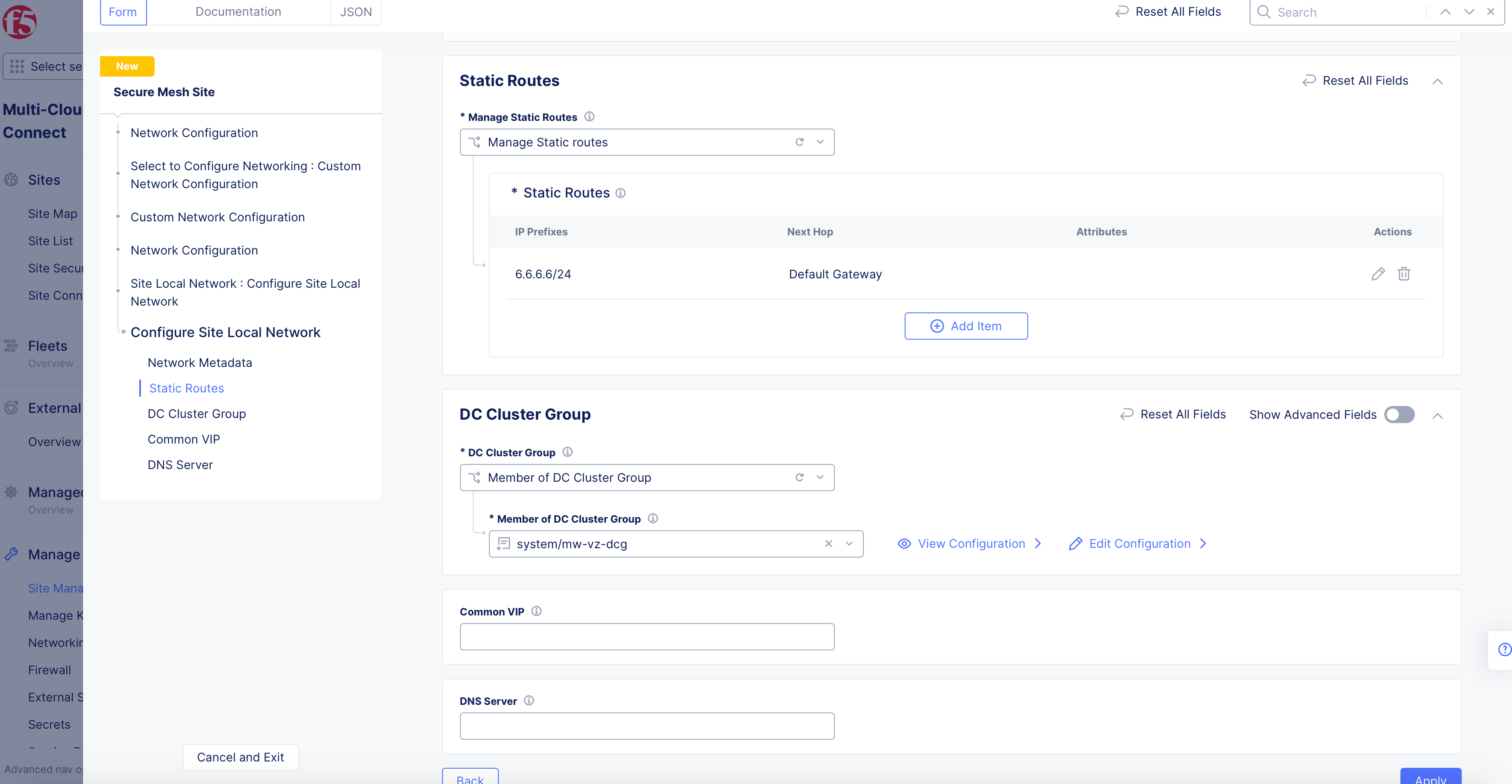
Figure: Site Local Network Configuration
- Select
Apply.
Note: For more information, see the Configure DC Cluster Group guide.
Step 4.2: Configure site local inside network settings.
Site local inside network is applied with default configuration. Perform the following set of steps to apply custom configuration:
-
Select
Configure Site Local Inside Networkfrom theSelect Configuration For Site Local Networkmenu. -
Select
Configure. -
Optionally, set labels for the
Network Labelsfield in theNetwork Metadatasection. -
Select
Manage Static Routesfrom theManage Static Routesmenu. -
Select
Add Itemand perform the following:-
Enter IP prefixes for the
IP Prefixessection. These prefixes are mapped to the same next-hop and attributes. -
Select
IP AddressorInterfaceorDefault Gatewayfrom theSelect Type of Next Hopmenu and specify IP address or interface accordingly. In the case ofInterface, you can select an existing interface or create a new interface using the options for the interface field. -
Optionally, select one or more options for the
Attributesfield to set attributes for the static route. -
Select
Apply.
-
Note: Use
Add Itemin theStatic Routessection to add more than one static route.
-
Optionally, configure
DC Cluster Groupusing the following guidelines:-
Select
Member of DC Cluster Groupfrom theSelect DC Cluster Groupmenu. -
In the
Member of DC Cluster Groupfield, select a DC cluster group. You can also selectCreate New DC Cluster Groupto create a new cluster group. Performing this adds this site to a DC cluster group, enabling full connectivity between the members of the group.
-
-
Select
Apply.
Note: For more information, see the Configure DC Cluster Group guide.
Step 4.3: Configure interface settings.
Bootstrap interface configuration is applied by default, and it is based on the certified hardware.
Perform the following to apply custom interface configuration:
-
Select
List of Interfacefrom theSelect Interface Configurationmenu. -
Click
Configure. This opens another interface list configuration page. -
Select
Add Itemin theList of Interfacetable. -
Optionally, enter an interface description and select labels.
-
Select an option from the
Interface Config Typemenu, and set one of the interface types using the following instructions:
Ethernet Interface:
-
Select
Ethernet Interfaceand clickConfigure. This opens Ethernet interface configuration page. -
Select an option from the
Ethernet Devicemenu usingSee Common Values. You can also type a custom name to set the device name while also adding it to the existing options. -
Select
Cluster, All Nodes of the SiteorSpecific Nodefrom theSelect Configuration for Cluster or Specific Nodemenu. In case of specific node, select the specific node from the displayed options of theSpecific Nodefield. You can also type a custom name to set the device name while also adding it to the existing options. -
Select
UntaggedorVLAN Idfrom theSelect Untagged or VLAN taggedmenu. In case of VLAN ID, enter the VLAN ID in theVLAN Idfield. -
Select an option from the
Select Interface Address Methodmenu in theIP Configurationsection. TheDHCP Clientis selected by default. In case you select a DHCP server, clickConfigureand set the DHCP server configuration per the options displayed on the DHCP server configuration page and clickApply. This example shows the interface as DHCP client for brevity. -
Select
Site Local Network (Outside),Site Local Network (Inside), orSegmentfrom theSelect Virtual Networkmenu in theVirtual Networksection. If you chooseSegment, you must also select the segment from the drop-down list.Site Local Network (Outside)is selected by default. -
Select if the interface is primary from the
Select Primary Interfacemenu. Default is not a primary interface. Ensure that you set only one interface as primary. -
Select
Apply.
Dedicated Interface:
-
Select
Dedicated Interfacefrom theInterface Config Typemenu. -
Select a device name from the
Interface Devicemenu usingSee Common Values. You can also type a custom name to set the device name while also adding it to the existing options. -
Select
Cluster, All Nodes of the SiteorSpecific Nodefrom theSelect Configuration for Cluster or Specific Nodemenu. In case of specific node, select the specific node from the displayed options from theSpecific Nodemenu. You can also type a custom name to set the device name while also adding it to the existing options. -
Select if the interface is primary in the
Select Primary Interfacefield. Default is not a primary interface. Ensure that you set only one interface as primary. -
Select
Add Item. -
Optionally, add more than one interface using the
Add Itemoption in theList of Interfacepage. -
Select
Apply.
Step 4.4: Configure security settings.
In case of security configuration, the firewall policies and forward policies are disabled by default.
In the Security Configuration section, perform the following to apply network and forward policies:
-
Select
Active Enhanced Firewall Policiesfrom theFirewall Policymenu and do the following:- Click
ConfigureunderEnhanced Firewall Policyto switch to enhanced firewall policies list page. - Select an enhanced firewall policy object from the
Enhanced Firewall Policydrop-down. You can also create and apply a new enhanced firewall policy using theAdd Itemin the drop-down. - Use
Add Itemin the list page to add more than one enhanced firewall policy.
- Click
-
Select
Active Firewall Policiesfrom theFirewall Policymenu and do the following:- Select a firewall policy object from the
Firewall Policydrop-down. You can also create and apply a new firewall policy using theAdd Itemoption. - Use
Add Itemin the list section to add more than one firewall policy.
- Select a firewall policy object from the
-
Select one of the following options from the
Forward Proxymenu:-
Select
Enable Forward Proxy and Manage Policiesto apply specific forward proxy policies. Select a forward proxy policy from theForward Proxy Policiesdrop-down. You can also create and apply a new forward proxy policy using theAdd Itemoption. You can apply more than one forward proxy policy using theAdd Itemoption in the list section. -
Select
Enable Forward Proxy With Allow All Policyto allow all requests.
-
Step 4.5: Configure global networks.
-
Enable
Show Advanced Fieldsin theGlobal Connectionssection. -
Select
Connect Global Networksfrom theGlobal Network Connectionsdrop-down. -
Click
Add Itemin theGlobal Network Connectionssection to open the global network connections page. -
Select one of the following for the
Select Network Connection Typefield:-
Direct, Site Local Inside to a Global Networkto connect site local inside network to global network. -
Direct, Site Local Outside to a Global Networkto connect site local outside network to global network.
-
-
Select a virtual global network from the
Global Virtual Networkdrop-down. You can also create and apply a new virtual global network usingAdd Item. -
Click
Applyto add global network connection to the Secure Mesh Site configuration.
Note: Use
Add Itemin theGlobal Network Connectionssection to add more than one global network connection.
Step 4.6: Configure Site Mesh Group Connection Type.
The default connection type for incoming tunnels for Site Mesh Group (SMG) is via private IP. This option uses the Site Local Outside interface addresses for creating IPsec tunnels between two sites that are part of the SMG.
To change the connection type, select Site Mesh Group Connection Via Public Ip from the Site Mesh Group Connection Type field. This option uses the statically configured public IPs of each master node for creating IPsec between two sites that are part of the SMG.
Step 4.7: Configure advanced settings.
In the Advanced Configuration section, do the following:
-
Select
Enable VRRP for VIP(s)forVIP Advertisement Mode. F5 recommends that you enable this and BGP if Outside VIP/Inside VIP are configured. -
Enter a value in milliseconds in the
Tunnel Dead Timeout (msec)field to detect dead tunnels within this time. By default, 10000 milliseconds is set.
Click Apply to add the custom network settings to the Secure Mesh Site configuration.
Step 5: Optionally, configure advanced features.
Do the following in the Advanced Configuration section of Secure Mesh Site main configuration page:
-
Select
Enable Logs Streamingfrom theLogs Streamingdrop-down and choose a log streaming object from the displayedEnable Logs Streamingdrop-down. This enables streaming of logs from the Site to the configured log receiver. For more information on log streaming configuration, see Logs Streaming. -
Select
F5XC Software Versionfrom theF5XC Software Versionfield and enter a specific version in the enabledF5XC Software Versionfield. By default, the latest software version is used. -
Select
Operating System Versionfrom theOperating System Versionfield and enter a specific version in the enabledOperating System Versionfield. By default, the latest OS version is used. -
Select
Custom Blocked Services Configurationfrom theBlocked Servicesfield, clickAdd Itemto customize the service type and port you want to block, and clickApplyto add the custom blocking configuration. -
Select
Enable Offline Survivability Modefrom theOffline Survivability Modefield to enable offline survivability mode.

Figure: Advanced Features
- Select
L3 Mode Enhanced Performancefrom thePerformance Modefield and choose to enable or disable jumbo frames using theL3 Mode Enhanced Performance Optionsfield options. The L7 Enhanced Mode is enabled by default for the performance mode.
Step 6: Complete creating the Secure Mesh Site.
Select Add Secure Mesh Site to complete creating the Secure Mesh Site.
Create Single-Node Secure Mesh Site
Step 1: Start creating Secure Mesh Site object.
-
In
Multi-Cloud Network Connectworkspace, navigate toManage>Site Management>Secure Mesh Sites. -
Select
Add Secure Mesh Siteto open the Secure Mesh Site configuration form.
Figure: Navigate to Secure Mesh Site Configuration
-
Enter a name in the
Metadatasection for your Secure Mesh Site object. -
Optionally, select labels and add a description.
Step 2: Set the fields for basic configuration.
-
From the
Generic Server Certified Hardwaremenu, select an option. Theisv-8000-series-voltmeshis selected by default. If theGeneric Server Certified Hardwareis not listed in the drop-down menu, type in the name for your deployment. This may be needed if you are manually deploying a site in the public cloud using the ClickOps method. -
Enter the name of the master node in the
Master Nodesfield.
Important: The name of the VM should not have "." in it. For example, the hostname can be node-0 or node0, but it cannot be node.f5.com since it is not supported. Your node VM name must adhere to DNS-1035 label requirements. This means the name must consist of lower case alphanumeric characters or “-“, start with an alphabetic character, and end with an alphanumeric character.
-
Enter the public IP in the
Public IPfield for the master node. The IP address is only used when a site is part of a Site Mesh Group, and you have selected theSite Mesh Group Connection Via Public Ipoption for theSite Mesh Group Connection Typefield as shown in Step 4.6. -
Leave the
Worker Nodessection empty, as worker nodes are not supported for single-node sites. -
Optionally, enter the following fields:
-
Geographical Address: This derives geographical coordinates.
-
Coordinates: Latitude and longitude.
-
Important: F5 recommends that you enter the coordinates so that the CE connects to the geographically closest REs.
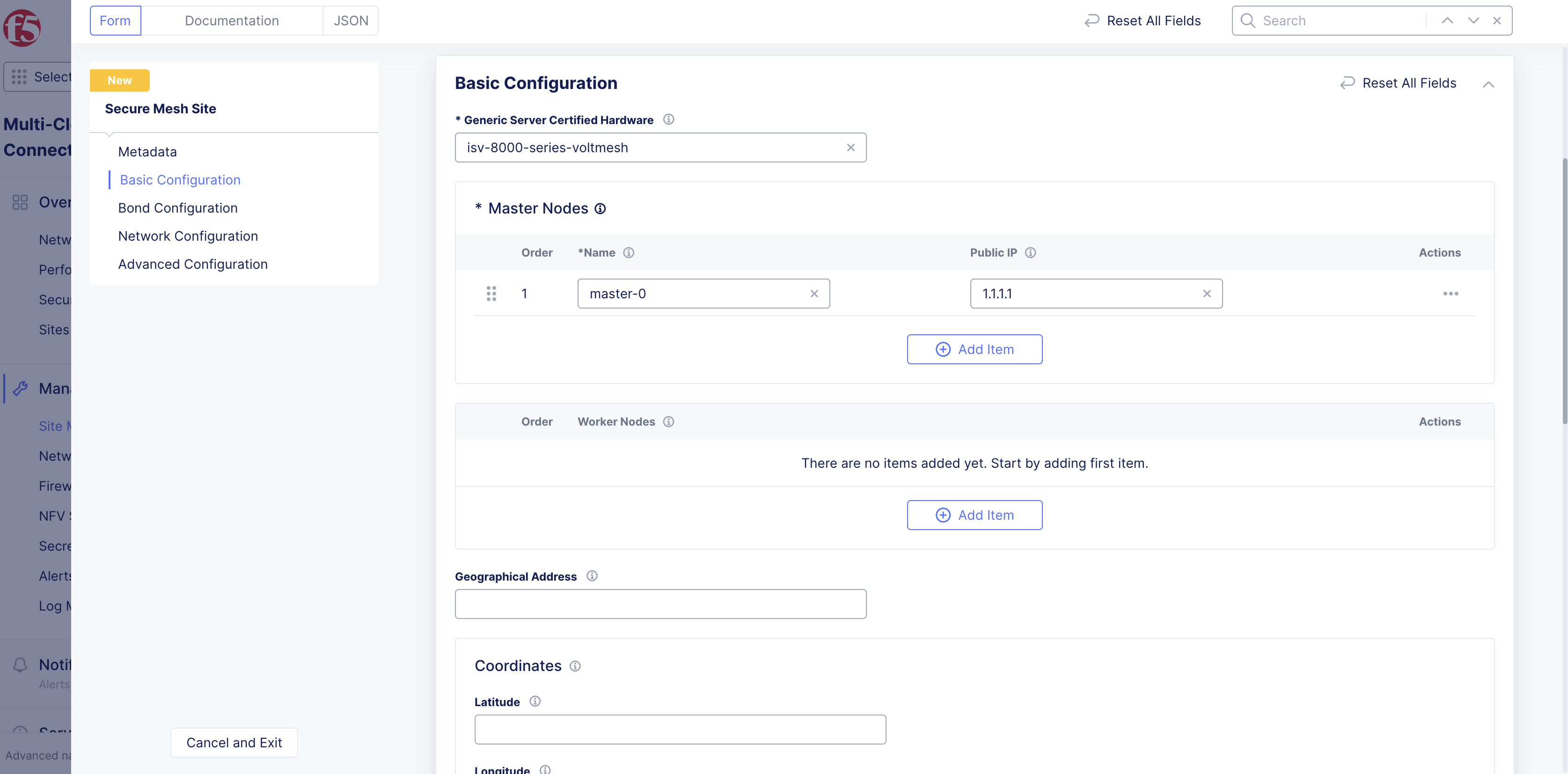
Figure: Single-Node Basic Configuration Section
Step 3: Optionally, configure bond interfaces.
In the Bond Configuration section, perform the following:
-
From the
Select Bond Configurationmenu, selectConfigure Bond Interfaces. -
Select
Configureto open bond interface configuration page. -
Select
Add Itemunder theBond Devices Listfield. -
Select on the
Bond Device Namefield and selectSee Common Values. You can also type a custom name and clickAdd Itemto set the device name while also adding it to the existing options. -
Select on the
Member Ethernet Devicesfield and selectSee Common Valuesfor the Ethernet device that is part of this bond. UseAdd Itemoption to add more devices. -
From the
Select Bond Modemenu, select the bonding mode.LACP (802.3ad)is selected by default for the bonding mode with the default LACP packet interval as 30 seconds. You can set the bond mode toActive/Backupto set the bond members function in active and backup combination. -
Select
Add Item.
Note: Use the
Add Itemoption in theBond Devices Listto add more than one bond device.
- Select
Applyin theBond Devicespage to apply the bond configuration.
Step 4: Optionally, configure network settings.
The network configuration is applied with default settings. To customize network settings, do the following:
-
In the
Network Configurationsection, selectCustom Network Configurationfrom theSelect to Configure Networkingmenu. -
Select
View Configurationto open the network configuration page and do the following:
Step 4.1: Configure site local network settings.
Site local network is applied with default configuration. Perform the following set of steps to apply custom configuration:
-
Select
Configure Site Local Networkfrom theSelect Configuration For Site Local Networkmenu. -
Select
View Configuration. -
Optionally, set labels for the
Network Labelsfield in theNetwork Metadatasection. -
Select
Manage Static Routesfrom theManage Static Routesmenu. -
Select
Add Itemand perform the following:-
Enter IP prefixes for the
IP Prefixessection. These prefixes are mapped to the same next-hop and attributes. -
Select
IP AddressorInterfaceorDefault Gatewayfrom theSelect Type of Next Hopmenu and specify IP address or interface accordingly. In the case ofInterface, you can select an existing interface or create a new interface using the options for the interface field. -
Optionally, select one or more options for the
Attributesfield to set attributes for the static route. -
Select
Apply.
-
Note: Use
Add Itemin theStatic Routessection to add more than one static route.
-
Optionally, configure
DC Cluster Groupusing the following guidelines:-
Select
Member of DC Cluster Groupfrom theSelect DC Cluster Groupmenu. -
In the
Member of DC Cluster Groupfield, select a DC cluster group. You can also selectCreate New DC Cluster Groupto create a new cluster group. Performing this adds this site to a DC cluster group, enabling full connectivity between the members of the group.
-
Figure: Site Local Network Configuration
- Select
Apply.
Note: For more information, see the Configure DC Cluster Group guide.
Step 4.2: Configure site local inside network settings.
Site local inside network is applied with default configuration. Perform the following set of steps to apply custom configuration:
-
Select
Configure Site Local Inside Networkfrom theSelect Configuration For Site Local Networkmenu. -
Select
Configure. -
Optionally, set labels for the
Network Labelsfield in theNetwork Metadatasection. -
Select
Manage Static Routesfrom theManage Static Routesmenu. -
Select
Add Itemand perform the following:-
Enter IP prefixes for the
IP Prefixessection. These prefixes are mapped to the same next-hop and attributes. -
Select
IP AddressorInterfaceorDefault Gatewayfrom theSelect Type of Next Hopmenu and specify IP address or interface accordingly. In the case ofInterface, you can select an existing interface or create a new interface using the options for the interface field. -
Optionally, select one or more options for the
Attributesfield to set attributes for the static route. -
Select
Apply.
-
Note: Use
Add Itemin theStatic Routessection to add more than one static route.
-
Optionally, configure
DC Cluster Groupusing the following guidelines:-
Select
Member of DC Cluster Groupfrom theSelect DC Cluster Groupmenu. -
In the
Member of DC Cluster Groupfield, select a DC cluster group. You can also selectCreate New DC Cluster Groupto create a new cluster group. Performing this adds this site to a DC cluster group, enabling full connectivity between the members of the group.
-
-
Select
Apply.
Note: For more information, see the Configure DC Cluster Group guide.
Step 4.3: Configure interface settings.
Bootstrap interface configuration is applied by default, and it is based on the certified hardware.
Perform the following to apply custom interface configuration:
-
Select
List of Interfacefrom theSelect Interface Configurationmenu. -
Click
Configure. This opens another interface list configuration page. -
Select
Add Itemin theList of Interfacetable. -
Optionally, enter an interface description and select labels.
-
Select an option from the
Interface Config Typemenu, and set one of the interface types using the following instructions:
Ethernet Interface:
-
Select
Ethernet Interfaceand clickConfigure. This opens Ethernet interface configuration page. -
Select an option from the
Ethernet Devicemenu usingSee Common Values. You can also type a custom name to set the device name while also adding it to the existing options. -
Select
Cluster, All Nodes of the SiteorSpecific Nodefrom theSelect Configuration for Cluster or Specific Nodemenu. In case of specific node, select the specific node from the displayed options of theSpecific Nodefield. You can also type a custom name to set the device name while also adding it to the existing options. -
Select
UntaggedorVLAN Idfrom theSelect Untagged or VLAN taggedmenu. In case of VLAN ID, enter the VLAN ID in theVLAN Idfield. -
Select an option from the
Select Interface Address Methodmenu in theIP Configurationsection. TheDHCP Clientis selected by default. In case you select a DHCP server, clickConfigureand set the DHCP server configuration per the options displayed on the DHCP server configuration page and clickApply. This example shows the interface as DHCP client for brevity. -
Select site local outside or site local inside network from the
Select Virtual Networkmenu in theVirtual Networksection.Site Local Network (Outside)is selected by default. -
Select if the interface is primary from the
Select Primary Interfacemenu. Default is not a primary interface. Ensure that you set only one interface as primary. -
Select
Apply.
Dedicated Interface:
-
Select
Dedicated Interfacefrom theInterface Config Typemenu. -
Select a device name from the
Interface Devicemenu usingSee Common Values. You can also type a custom name to set the device name while also adding it to the existing options. -
Select
Cluster, All Nodes of the SiteorSpecific Nodefrom theSelect Configuration for Cluster or Specific Nodemenu. In case of specific node, select the specific node from the displayed options from theSpecific Nodemenu. You can also type a custom name to set the device name while also adding it to the existing options. -
Select if the interface is primary in the
Select Primary Interfacefield. Default is not a primary interface. Ensure that you set only one interface as primary. -
Select
Add Item. -
Optionally, add more than one interface using the
Add Itemoption in theList of Interfacepage. -
Select
Apply.
Step 4.4: Configure security settings.
In case of security configuration, the firewall policies and forward policies are disabled by default.
In the Security Configuration section, perform the following to apply network and forward policies:
-
Select
Active Enhanced Firewall Policiesfrom theFirewall Policymenu and do the following:- Click
ConfigureunderEnhanced Firewall Policyto switch to enhanced firewall policies list page. - Select an enhanced firewall policy object from the
Enhanced Firewall Policydrop-down. You can also create and apply a new enhanced firewall policy using theAdd Itemin the drop-down. - Use
Add Itemin the list page to add more than one enhanced firewall policy.
- Click
-
Select
Active Firewall Policiesfrom theFirewall Policymenu and do the following:- Select a firewall policy object from the
Firewall Policydrop-down. You can also create and apply a new firewall policy using theAdd Itemoption. - Use
Add Itemin the list section to add more than one firewall policy.
- Select a firewall policy object from the
-
Select one of the following options from the
Forward Proxymenu:-
Select
Enable Forward Proxy and Manage Policiesto apply specific forward proxy policies. Select a forward proxy policy from theForward Proxy Policiesdrop-down. You can also create and apply a new forward proxy policy using theAdd Itemoption. You can apply more than one forward proxy policy using theAdd Itemoption in the list section. -
Select
Enable Forward Proxy With Allow All Policyto allow all requests.
-
Step 4.5: Configure global networks.
-
Enable
Show Advanced Fieldsin theGlobal Connectionssection. -
Select
Connect Global Networksfrom theGlobal Network Connectionsdrop-down. -
Click
Add Itemin theGlobal Network Connectionssection to open the global network connections page. -
Select one of the following for the
Select Network Connection Typefield:-
Direct, Site Local Inside to a Global Networkto connect site local inside network to global network. -
Direct, Site Local Outside to a Global Networkto connect site local outside network to global network.
-
-
Select a virtual global network from the
Global Virtual Networkdrop-down. You can also create and apply a new virtual global network usingAdd Item. -
Click
Applyto add global network connection to the Secure Mesh Site configuration.
Note: Use
Add Itemin theGlobal Network Connectionssection to add more than one global network connection.
Step 4.6: Configure Site Mesh Group Connection Type.
The default connection type for incoming tunnels for Site Mesh Group (SMG) is via private IP. This option uses the Site Local Outside interface addresses for creating IPsec tunnels between two sites that are part of the SMG.
To change the connection type, select Site Mesh Group Connection Via Public Ip from the Site Mesh Group Connection Type field. This option uses the statically configured public IPs of each master node for creating IPsec between two sites that are part of the SMG.
Step 4.7: Configure advanced settings.
In the Advanced Configuration section, do the following:
-
Select
Enable VRRP for VIP(s)forVIP Advertisement Mode. F5 recommends that you enable this and BGP if Outside VIP/Inside VIP are configured. -
Enter a value in milliseconds in the
Tunnel Dead Timeout (msec)field to detect dead tunnels within this time. By default, 10000 milliseconds is set.
Click Apply to add the custom network settings to the Secure Mesh Site configuration.
Step 5: Optionally, configure advanced features.
Do the following in the Advanced Configuration section of Secure Mesh Site main configuration page:
-
Select
Enable Logs Streamingfrom theLogs Streamingdrop-down and choose a log streaming object from the displayedEnable Logs Streamingdrop-down. This enables streaming of logs from the Site to the configured log receiver. For more information on log streaming configuration, see Logs Streaming. -
Select
F5XC Software Versionfrom theF5XC Software Versionfield and enter a specific version in the enabledF5XC Software Versionfield. By default, the latest software version is used. -
Select
Operating System Versionfrom theOperating System Versionfield and enter a specific version in the enabledOperating System Versionfield. By default, the latest OS version is used. -
Select
Custom Blocked Services Configurationfrom theBlocked Servicesfield, clickAdd Itemto customize the service type and port you want to block, and clickApplyto add the custom blocking configuration. -
Select
Enable Offline Survivability Modefrom theOffline Survivability Modefield to enable offline survivability mode.
Figure: Advanced Features
- Select
L3 Mode Enhanced Performancefrom thePerformance Modefield and choose to enable or disable jumbo frames using theL3 Mode Enhanced Performance Optionsfield options. The L7 Enhanced Mode is enabled by default for the performance mode.
Step 6: Complete creating the Secure Mesh Site.
Select Add Secure Mesh Site to complete creating the Secure Mesh Site.
Deploy the Site Nodes
A secure mesh site can be created on any supported provider. The steps to create the actual site nodes differ based on your environment/cloud environment (where your site is created).
Follow the deployment steps in the document appropriate for your provider environment:
- Create VMware Site
- Create KVM Site
- Create Baremetal Site
- Deploy Site in AWS (ClickOps)
- Deploy Site in Azure (ClickOps)
- Deploy Site in GCP (ClickOps)
Register Site
After you install the Distributed Cloud Services Node, you must register it as a site in the Distributed Cloud Console.
Perform registration per the following instructions:
Register Multi-Node Site
Step 1: Navigate to the site registration page.
-
Log into Console.
-
Click
Multi-Cloud Network Connect. -
Click
Manage>Site Management>Registrations.
Step 2: Accept the registration requests.
Registration requests are displayed in the Pending Registrations tab.
-
Click
Acceptto accept the registration requests from themaster-0,master-1, andmaster-2nodes. The node names differ. -
Enter the same values for the following parameters for all the registration requests:
-
In the
Cluster namefield, enter a name for the cluster. Ensure that all master nodes have the same name. -
In the
Cluster sizefield, enter3. Ensure that all master nodes have the same cluster size.
-
-
Enter all mandatory fields marked with the asterisk (
*) character. -
Click
Save Secure Mesh Site.
Step 3: Check site status and health.
It may take a few minutes for the site health and connectivity score information to update.
-
Click
Overview>Infrastructure>Sites. -
Click on your site name. The
Dashboardtab appears, along with many other tabs to inspect your site. -
Click the
Site Statustab to verify the following:-
The
Update Statusfield has aSuccessfulvalue for theF5 OS Statussection. -
The
Update Statusfield has aSuccessfulvalue for theF5 Software Statussection. -
The
Tunnel statusandControl Planefields under theRE Connectivitysection haveupvalues.
-
Note: The factory reset functionality is not supported. To update a site node, power off and then destroy it. Perform the same procedure as above to recreate a virtual machine (VM).
Register Single-Node Site
Step 1: Navigate to the site registration page.
-
Log into Console.
-
Click
Multi-Cloud Network Connect. -
Click
Manage>Site Management>Registrations.
Step 2: Accept the registration requests.
Registration requests are displayed in the Pending Registrations tab.
-
Click
Acceptto accept the registration request for the node. -
In the form that appears, enter all mandatory fields marked with the asterisk (
*) character. -
Enter latitude and longitude values if you did not previously.
-
Enter other configuration information, if needed.
-
Click
Save Secure Mesh Site.
Step 3: Check site status and health.
It may take a few minutes for the site health and connectivity score information to update.
-
Click
Overview>Infrastructure>Sites. -
Click on your site name. The
Dashboardtab appears, along with many other tabs to inspect your site. -
Click the
Site Statustab to verify the following:-
The
Update Statusfield has aSuccessfulvalue for theF5 OS Statussection. -
The
Update Statusfield has aSuccessfulvalue for theF5 Software Statussection. -
The
Tunnel statusandControl Planefields under theRE Connectivitysection haveupvalues.
-
Note: The factory reset functionality is not supported. To update a site node, power off and then destroy it. Perform the same procedure as above to recreate a virtual machine (VM).