Create AWS Site with TGW (Orchestrated)
Objective
This guide provides instructions on how to create an F5® Distributed Cloud Services Amazon Web Services (AWS) Transit Gateway (TGW) site using F5® Distributed Cloud Console (Console).
You can create an AWS TGW site if you want to secure, connect, or load balance workloads across multiple Virtual Private Clouds (VPCs) in an AWS region from a single service VPC that connects to the workload VPCs using the TGW. This site type allows you to centrally enforce and manage security policies for traffic from one spoke VPC to another (East-West) and also form a spoke VPC to any other site on the F5 Distributed Cloud fabric or to the Internet.
Important: This site type does not support App Stack mode.
Customer Edge Node Clustering
An AWS TGW site can be deployed as a single-node site or as a three-node site. These nodes host the control processes, data plane processes, and the IPsec connections to the Regional Edges (REs). For production deployments, a three-node site is recommended as it provides high availability. Additional worker nodes can also be deployed after the site is created for additional capacity for L7 features, like load balancing, WAAP, and more.
Note: Worker nodes are only supported for three-node sites.
Design
The figure below shows the AWS TGW site deployment with TGW attachments and route tables. A single-node deployment diagram is shown for simplicity.
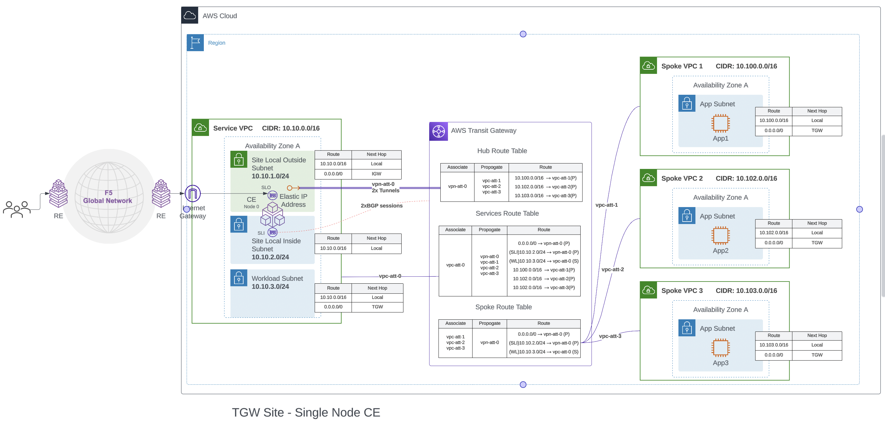
Figure: Single-Node Deployment
AWS Orchestration
The AWS TGW site automates the creation of the following objects:
-
The service VPC, with associated objects:
- Site Local Outside (SLO), Site Local Inside (SLI), Workload subnets, and associated route tables
- Internet Gateway (IGW)
- CE instances
-
Transit Gateway (TGW)
-
Elastic IP for each node
-
VPN attachments between CE and TGW with two tunnels
-
VPC attachments attaching the service and spoke VPC to TGW
-
TGW route tables
-
Update routes in the main route table of every spoke VPC
The CE peers with the TGW using BGP to exchange routes. The VPN tunnels are between the TGW and elastic IP on the SLO of the CE nodes, but the TGW peers using BGP with the CE to its internal tunnel interface on the SLI side. Thus, the BGP routes are learned on the SLI.
The automation process also creates a static route on the TGW pointing to the workload subnet on the service VPC. This is required because the TGW only learns about the CE’s internal fabric routes over BGP and not the service VPC routes. This route is used when network functions virtualization (NFV) services are configured on the service VPC.
VPC Attachments
You can add spoke VPCs to the site configuration during the initial site object creation or after the site is created. If the spoke is added after the site is created, it requires an apply action on the Console for the VPC attachment to be created for that spoke. Site deployment workflow will also create a default route pointing to the transit gateway in the main route table of all VPCs attached to the TGW.
Note: The deployment automation process will only update the main route table. You must associate the application subnet with the main route table for the proper routing of traffic to the site. If the spoke application subnet is associated with other user-created route tables, it must be updated to have the default route point to the TGW for proper operation.
TGW Routing Details
The AWS TGW site creates routes on spoke VPCs, service VPCs, and the TGW to direct all traffic from the spokes to the CE nodes.
The TGW has three route tables:
-
Hub route table: The hub route table is associated to the VPN connection between the site and the TGW. The routes of spoke VPCs attached to the TGW will be propagated into this route table. The site will learn these routes via the BGP peering to the TGW over the VPN.
-
Spoke route table: The spoke route table is associated with all the spoke VPC attachments. The routes learned from the site via BGP over VPN attachment are propagated to this route table. The site-advertised default route will be installed in the VPC route table so that it can attract all the traffic coming from the spoke VPC attachments. The automation process also creates a static route towards the workload subnet in the service VPC with the VPC attachment to the service VPC as the next hop. This route is used for traffic flows when an NFV service is enabled on the site.
-
Service route table: The services route table is associated to the VPN connection to the site. The routes of spoke VPCs attachments and site VPN attachments to the TGW will be propagated into the services route table.
Only the hub route table and the spoke route table are used for regular L3 traffic routing to and from the spoke VPCs. The service route table is used only when an NFV service is configured and an external service instance is running on the workload subnet. Using these route tables, the AWS TGW directs the traffic.
As an example, we take traffic to and from spoke VPC 1 (CIDR 10.100.0.0/16):
- Egress from spoke VPC: Traffic originating from source 10.100.0.0/16 lands in the spoke route table. All traffic will match the 0.0.0.0/0 route pointing to vpn-att-0 toward the CE nodes installed in the service VPC. The traffic will be Equal Cost Multi-Path (ECMP) over the two tunnels on the VPN.
Note: For a three-node CE, there will be three VPN attachments in total (one for each node), with a total of six tunnels (two tunnels per VPN). In this case, the 0.0.0.0/0 route will point to all three VPN attachments (vpn-att-0 to vpn-att-3). The AWS TGW will use ECMP to distribute the traffic over the tunnel endpoints as the next hops.
- Ingress to spoke VPC: Traffic originating from source (anywhere) coming via the CE node will land on the hub route table over the VPN attachment. It will match destination 10.100.0.0/16 with the next hop of vpc-att-1. Traffic is then forwarded to the spoke VPC 1.
Application Traffic Flow In AWS TGW Site
The below scenarios show how workload traffic is routed through the CE.
East-West Traffic
For a VM on a spoke VPC sending traffic to a VM on another spoke VPC:
- The traffic will match the default route of the VPC’s main routing table and will be sent to the TGW.
- The TGW’s spoke route table will forward traffic to the CE nodes as the default route points to the VPN attachments.
- The site’s routing table has VPC routes learned from TGW. This will forward the traffic back to the TGW.
- The TGW hub route table will look up the destination address and match it to the correct spoke VPC attachment.
- On the spoke VPC, the traffic will be routed to the correct instance.
North-South Egress Traffic
For a VM on a spoke VPC sending traffic to the Internet:
- The traffic will match the default route of the VPC’s main routing table and will be sent to the TGW.
- The TGW’s spoke route table will forward traffic to the CE site as the default route points to the VPN attachments.
- In the site route table, the default route points to the forward proxy if it is enabled or to the default gateway via the outside interface otherwise. Source Network Address Translation (SNAT) is performed on the outside interface and traffic is sent to the IGW.
North-South Ingress Traffic
For external traffic coming over global network or local public VIP on the site to a VM in a spoke VPC, the traffic will first land on the CE data path:
- The traffic will match the VPC routes learned from the TGW and will be routed to the TGW over VPN attachment
- The TGW hub route table will look up the destination address and match it to the correct spoke VPC attachment. On the spoke VPC, the traffic will be routed to the correct instance.
Centralized Security
All east-west and north-south traffic passes through the AWS TGW site. Therefore, it can centrally enforce security policies and other network functions for all spokes by configuring it on the site.
Network Policies Between Attached VPCs (East-West Traffic)
It is a common use case for enterprises to have workloads of one department or environment spread across multiple VPCs, and one must be able to create a single network policy that could be applied to multiple VPCs attached. For such scenarios, you can assign the same labels to the required VPCs attached to the TGW. The same labels can be used as the label selector while selecting an endpoint during network policy. You can then define ingress and egress policies concerning that endpoint. This network policy will be applied for all traffic going towards or coming from the VPCs that match the label selector labels.
Network Policies for Ingress/Egress Traffic
Even for ingress/egress traffic, you can use a label selector to select the VPCs for which you are defining the network policy. You can define the egress policy by adding the egress rules from the point of VPC to deny/allow a specific traffic pattern. You can also add ingress rules to deny/allow traffic coming toward the endpoint based on the intent.
Forward Proxy Policy for Attached VPCs
Using a forward proxy policy, you can specify allowed/denied TLS domains or HTTP URLs. The traffic from workloads on private subnets toward the Internet via the AWS TGW site will be filtered accordingly.
Private Connectivity
Private connectivity enables you to privately connect your on-premises data centers to the service VPC in which the Distributed Cloud Services sites are hosted so that the traffic does not flow over the public Internet. If this private connectivity is provisioned to the F5 Distributed Cloud Services REs, the site registration can be configured to go over the private connection.
There are two private connectivity options available: AWS Direct Connect (Legacy) and CloudLink.
AWS Direct Connect (Legacy): Distributed Cloud Services can orchestrate AWS Direct Connect to a VPC site. The automation orchestrates the creation of the Virtual Private Gateway and Direct Connect Gateway (DCGW) in addition to the regular site creation. The prerequisite is that the Direct Connect connection is created and managed by the user.
The on-premises data center routes are advertised by on-premises routers connected to AWS routers via Direct Connect. These routes are propagated to the VGW by the Direct Connect Gateway. VGW configures these routes in the VPC route table from where it is learned on the inside network of the site.
There are two supported modes of Direct Connect private Virtual Interface (VIF):
-
Standard VIF: In this mode, the whole Direct connect connection is used for the site. After site creation, you must associate the VIF on the DCGW using the AWS Console and configure BGP peering.
-
Hosted VIF: In this mode, site orchestration accepts the configured list of VIFs delegated from the Direct Connect connection owner account to the hosted VIF acceptor account. You can set a list of VIF IDs to be accepted. The site orchestration automates the association of the VIFs to the DCGW.
A single-node deployment diagram is shown for simplicity.
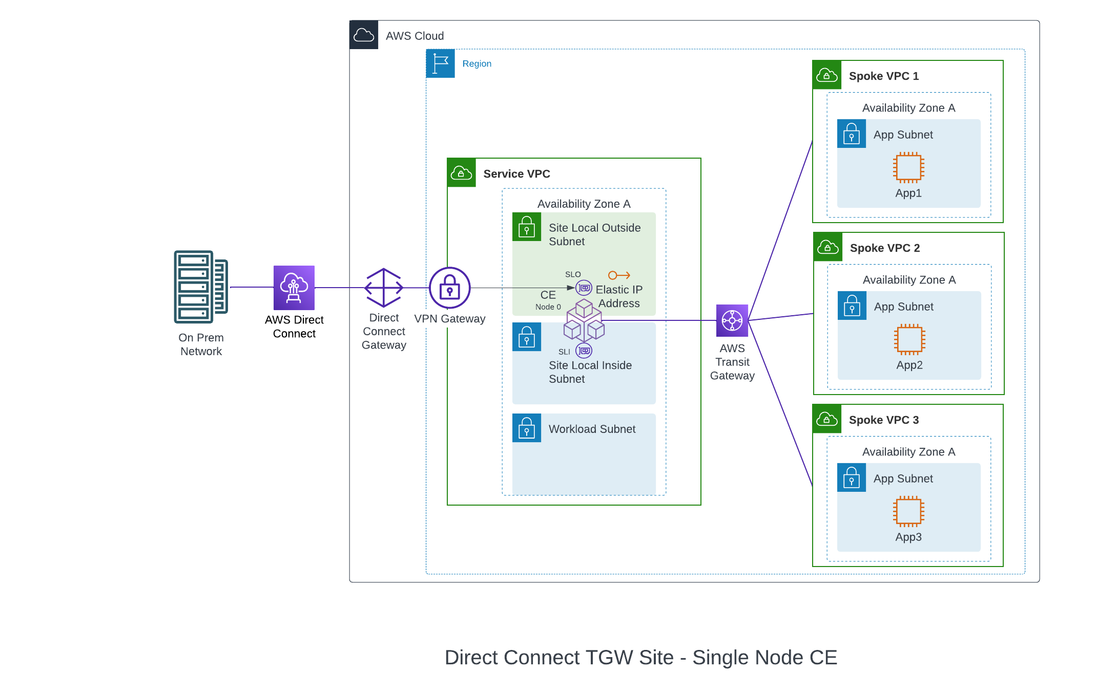
Figure: Single-Node Deployment with Direct Connect
CloudLink: A CloudLink allows Distributed Cloud Services to orchestrate an already provisioned direct connection, establish a multi-cloud networking fabric, and then connect, deliver, secure, and operate networks and apps across hybrid environments. For more information, see CloudLink.
Site Status Descriptions
These descriptions provide information for the various stages of site deployment in Distributed Cloud Console. They also provide information to help you troubleshoot errors that may occur during the deployment and registration stages.
PLANNING: Site resources are being planned for creation.
PLAN_INIT_ERRORED: Planning of site resources failed at init stage.
PLAN_ERRORED: Planning of site failed with errors.
PLAN_QUEUED: Planning of site resources queued to be implemented.
APPLIED: Site resources are created, and site is waiting to come online.
APPLY_ERRORED: Creation of site resources failed with errors.
APPLY_INIT_ERRORED: Creation of site resources failed with errors at initial stage.
APPLYING: Site creation is in progress.
APPLY_PLANNING: Site resources are being planned.
APPLY_PLAN_ERRORED: Planning of site failed with errors.
APPLY_QUEUED: Creation of site resources queued to be implemented.
DESTROYED: Site resources are destroyed and site is OFFLINE.
DESTROY_ERRORED: Destroying of site resources failed with errors.
DESTROYING: Destroying of site resources in progress.
DESTROY_QUEUED: Destroying of site resources queued to be destroyed.
GENERATED: Site Object created in F5 Distributed Cloud Console database as per configuration.
TIMED_OUT: Creation/Destroying of site resources is failed with a timeout.
ERRORED: Creation/Destroying of site resources is failed with errors.
PROVISIONING: Site resources are created and waiting for site to come online.
Prerequisites
The following prerequisites apply:
General
-
A Distributed Cloud Services Account. If you do not have an account, see Getting Started with Console.
-
An AWS Account. See Required Access Policies for permissions needed to deploy site. To create a cloud credentials object, see Create Cloud Credentials.
-
Resources required per node:
- vCPUs: Minimum 8 vCPUs.
- Memory: 32 GB RAM.
- Disk storage: Minimum 80 GB for Mesh site.
Note: For a full listing of the resources required, see the Customer Edge Site Sizing Reference guide. All the nodes in a given CE Site should have the same resources regarding the compute, memory, and disk storage. When deploying in cloud environments, these nodes should use the same instance flavor.
-
Instance type with Intel x86-based processor. ARM and Mac instances are not supported. Recommended instance types are:
- m5.2xlarge
- m5.4xlarge
-
Allow traffic from and to the Distributed Cloud public IP addresses to your network and allowlist related domain names. See F5 Customer Edge IP Address and Domain Reference for Firewall or Proxy Settings guide for the list of IP addresses and domain names.
-
Internet Control Message Protocol (ICMP) needs to be opened between the CE nodes on the Site Local Outside (SLO) interfaces. This is needed to ensure intra-cluster communication checks.
Important: After you deploy the CE Site, the IP address for the SLO interface cannot be changed. Also, the MAC address cannot be changed.
Existing VPC
VPC ID, subnet IDs, and AZ to be used for the deployment.
The existing subnets selected for Site Local Outside, Site Local Inside, and Workload subnets must not have an explicit association with any route tables. New route tables will be created and associated with these subnets. The deployment will fail if the subnets have existing custom route table associations.
Private Connectivity
- Direct Connect connection.
- VIF IDs if you are using hosted VIF mode.
Deploy Using Console
You can create and manage an AWS TGW site in Console by first creating the site object using the guided wizard and then deploying it using the automated method.
Create AWS TGW Site Object
The wizard to create the AWS TGW site object guides you through the steps for required configuration.
Step 1: Start site object creation.
-
Log into Console.
-
Click
Multi-Cloud Network Connect.
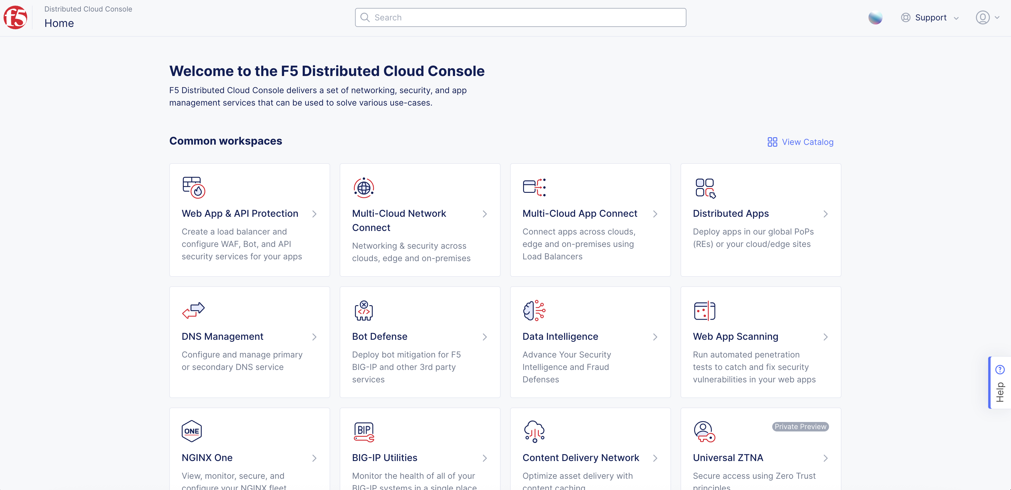
Figure: Console Homepage
-
Click
Manage>Site Management>AWS TGW Sites. -
Click
Add AWS TGW Site.
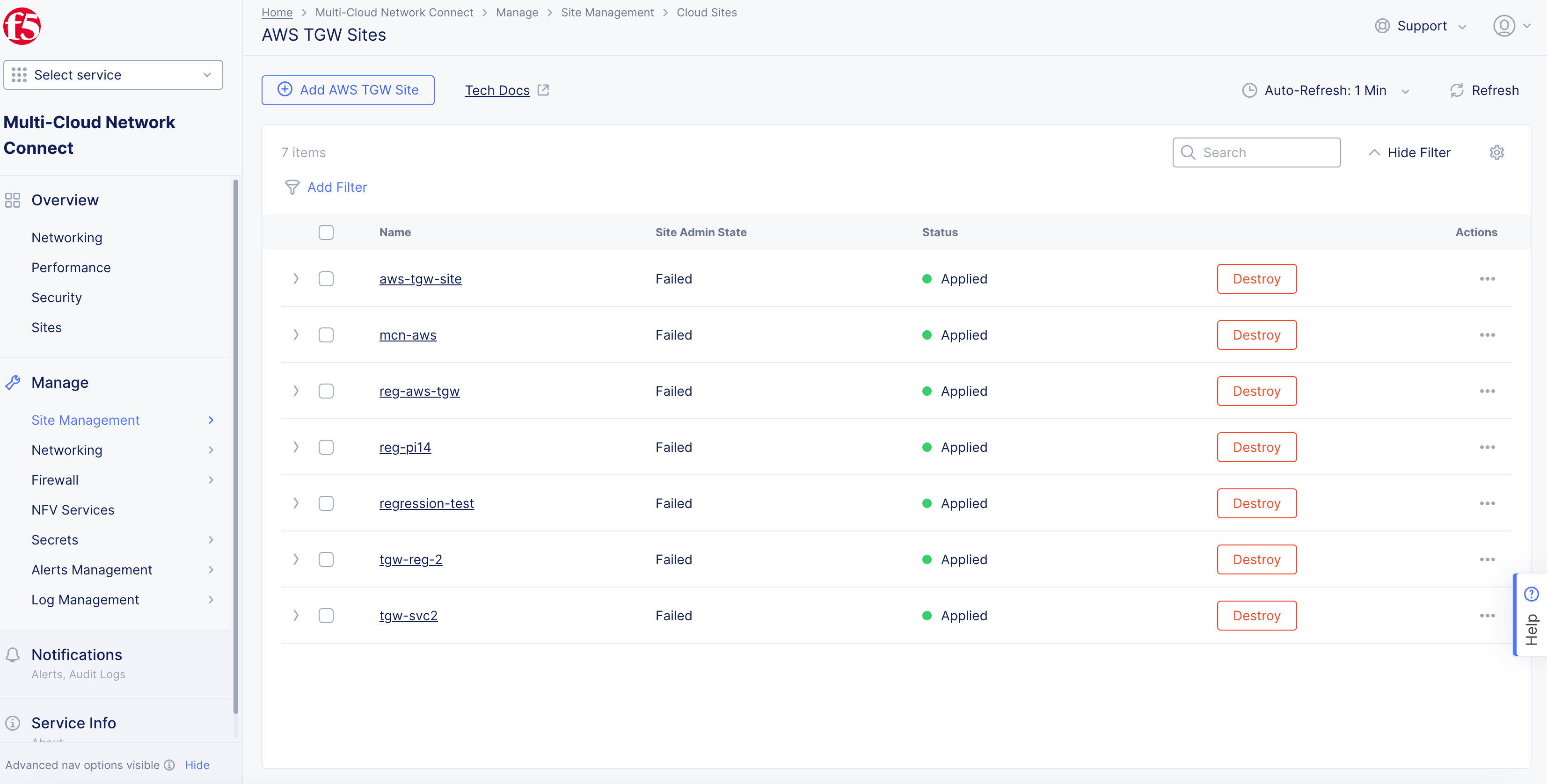
Figure: Create AWS TGW Object
-
In the
Metadatasection, enter a name for the TGW site object. -
Optionally, in the
Labelsfield, clickAdd Labelto select an existing label from the drop-down menu or type to add new labels. -
Optionally, add a description for the site.
Step 2: Configure region and services VPC settings.
-
In the
AWS Resourcessection, clickConfigureunderAWS Credentials and Resources. -
From the
Credential Referencemenu, select an existing AWS credentials object or clickAdd Itemto load the new credential creation wizard. Refer to the Cloud Credentials guide for more information. Ensure that the AWS credentials are applied with required access policies in accordance with the Policy Requirements document. -
From the
AWS Regionmenu, select the region based on your AWS account.
Step 2.1: Configure services VPC.
-
From the
New/Existing Services VPCmenu, select an option and configure per the following guidelines:- For the
New VPCoption, select an option from theNew VPCmenu. TheAutogenerate VPC Nameoption is selected by default. If you select theChoose VPC Nameoption, enter a VPC name in theExisting VPC Namefield.
- For the
Note: If you are using an existing VPC, ensure that you enable the
Enable DNS hostnamescheckbox in AWS Management Console (underEdit VPC settings) and ensure that the EC2 hostname is inip-*format in the subnet settings. The deployment will fail if the AWS subnet settings have the EC2 hostname type set to the resource name.
-
Enter the Classless Inter-Domain Routing (CIDR) block in the
Primary IPv4 CIDR blockfield. -
From the
Security Groupmenu, choose an automated or user-defined security group for the site:-
Choose the
Select this option to create and attach F5XC default security groupoption to allow automated security group creation for SLI and SLO interfaces. Auto-created security group allows all traffic on incoming and outgoing directions and security is enforced on the CE’s data path. -
Choose the
Select this option to specify custom security groups for SLO and SLI interfacesoption to use existing security groups for site deployment in existing VPC. This allows you to define security rules for the site on the cloud in addition to security enforcement on the CE’s data path. Check prerequisites for the list of ports and protocols to which CE access is required.
-
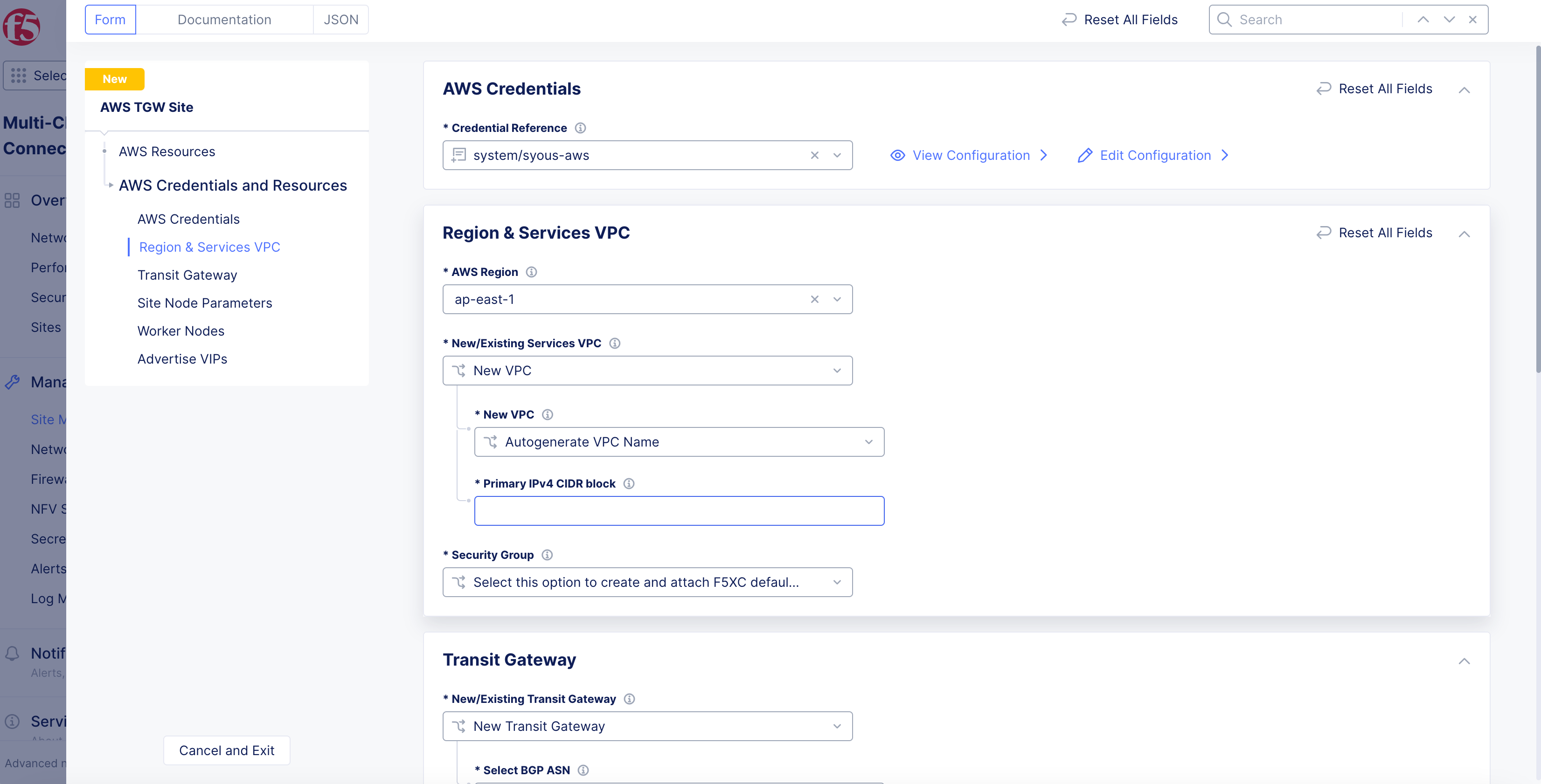
Figure: New Services VPC Configuration
Step 2.2: Configure the TGW settings.
-
In the
Transit Gatewaysection, select an option from theNew/Existing Transit Gatewaymenu, and configure per the following guidelines:-
For the
New Transit Gatewayoption, select an option from theSelect BGP ASNmenu. If you selectAutomatic, Distributed Cloud Services assign the ASNs for the TGW and site. For theUser will assign ASN for TGW and F5XC Siteoption, enter the ASNs forEnter TGW ASNandEnter F5XC Site ASNfields. The supported ASN range is from 64513 to 65534. -
For the
Existing TGWoption, enter the TGW ID in theExisting TGW IDfield. Enter the ASNs forEnter TGW ASNandEnter F5XC Site ASNfields.
-
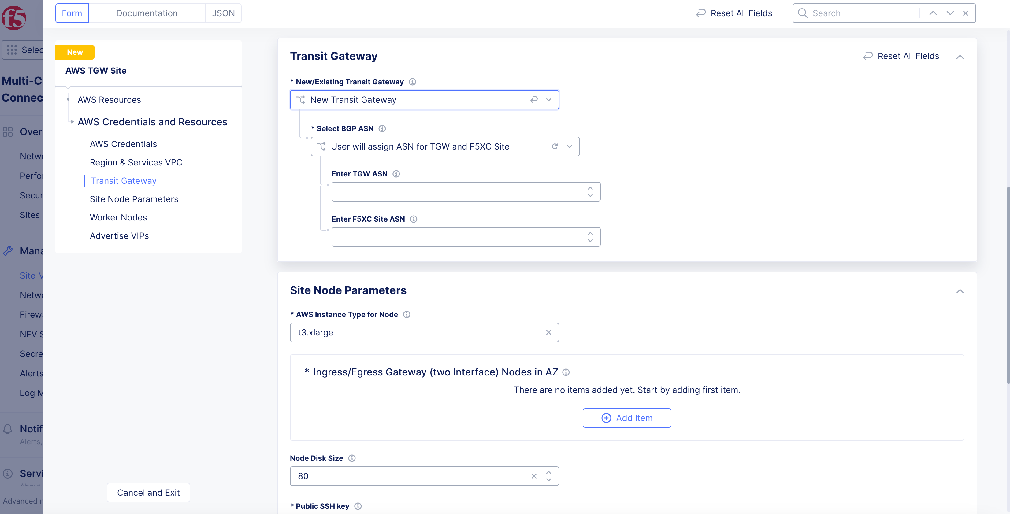
Figure: TGW Configuration
Step 2.3: Configure site node parameters.
-
In the
Site Node Parameterssection, configure per the following guidelines:-
From the
AWS Instance Type for Nodemenu, select an option. See the Prerequisites section for more information. -
In the
Node Disk Sizefield, leave the default value of80or enter a custom amount in gigabytes (GB). See the Prerequisites section for more information. -
In the
Ingress/Egress Gateway (two Interface) Nodes in AZfield, clickAdd Item.
-
Note: Either a single control node site or a multi-node site with three (3) control nodes is supported. Therefore, if you are adding more than one node, ensure that there are three (3) control nodes for your site. Use
Add Itemto add more control nodes.
-
Select an option from the
AWS AZ Namemenu that matches the configuredAWS Region. -
From the
Workload Subnetmenu, selectNew SubnetorExisting Subnet ID.
Note: Workload subnet is the network where your application workloads are hosted. For successful routing toward applications running in workload subnet, an inside static route to the workload subnet CIDR needs to be added on the respective site object.
-
Enter a subnet address in the
IPv4 Subnetfield or a subnet ID inExisting Subnet IDfield. Confirm the subnet is part of the VPC and CIDR block set for the site. -
From the
Subnet for Outside Interfacemenu, selectNew SubnetorExisting Subnet ID. -
Enter a subnet address in the
IPv4 Subnetfield or a subnet ID in theExisting Subnet IDfield. Confirm the subnet is part of the VPC and CIDR block set for the site. -
From the
Subnet for Inside Interfacemenu, select if you want the subnet details to be auto-generated or user-specified. For user-specified subnet, SelectNew SubnetorExisting Subnet IDfrom theSpecify Subnetmenu. -
Enter a new subnet address in the
IPv4 Subnetfield or a subnet ID in theExisting Subnet IDfield. Confirm the subnet is part of the VPC and CIDR block set for the site.
Note: New subnet creation is not supported for brownfield deployment with existing VPC selected for the site. An existing subnet ID must be provided in this case.
-
Click
Apply. -
For a three-node cluster, click on
Add Itemand repeat the above steps to specify AZ details for the other two nodes. Configure a different AZ for each node (for a total of three AZs). -
In the
Public SSH keybox, enter the public key used for SSH purposes.
Step 2.4: Configure worker nodes.
In the Worker Nodes section, select an option to add more nodes based on site or availability zone (AZ) from the Desired Worker Nodes for the site menu:
-
Select
Desired Worker Nodes Per AZand enter the number of worker nodes. The number of worker nodes you set here will be created per the availability zone in which you created nodes. For example, if you configure three nodes in three availability zones, and set theDesired Worker Nodes Per AZbox as 3, then 3 worker nodes per availability zone are created and the total number of worker nodes for this site will be 9. -
Select
Total Number of Worker Nodes for a Siteand specify the number of worker nodes if you want automation to automatically place the nodes evenly across the AZs. -
No Worker Nodes: default option selected.
Important: Worker nodes are only supported for sites with three (3) control nodes and will be deployed on the same AZs that were selected for the control nodes.
Step 2.5: Configure advertise VIP.
-
In the
Advertise VIPssection, select whether to enable advertising the site IP to the Internet from theAdvertise VIPs to Internet on Sitemenu. See the following options:-
Disable VIP Advertisement to Internet on Site: This is the default selection to disable public VIP creation directly on the service VPC. Apps can be advertised to the Internet using anycast VIP on the RE when you select advertising to the Internet for the load balancer advertise policy. -
Enable VIP Advertisement to the Internet on Site: This option enables public VIP creation directly on the service VPC. You may choose this if you want a unicast VIP owned by your AWS account and do not want to advertise to the Internet over the REs.
-
-
Click
Apply.
Step 3: Optionally, configure VPC attachments.
-
In the
VPC Attachmentssection, perform the following: -
Click
Configure. -
Click
Add Item. -
Enter the VPC ID of the spoke VPC you want to attach to the AWS TGW site, in the
VPC IDfield. Add any required labels usingAdd Label. The labels can be used to configure network policies for the spoke VPC. -
Click
Applyto save the VPC settings. -
Click
Applyto apply the VPC settings. -
Add multiple VPC attachments using
Add Item.
Note: You can also add VPCs after the site is created by editing the TGW site and adding a new VPC attachment. Apply action is required after this config change.
Step 4: Optionally, perform site network configuration.
- In the
Site Network and Securitysection, clickConfigureforSite Networking.
Step 4.1: Configure site-to-site L3 connectivity.
-
From the
Select Global Networks to Connectmenu, selectConnect Global Networksand then perform the following:-
Click
Add Item. -
From the
Select Network Connection Typemenu, select an option:-
Select
Direct Site Local Inside to a Global Networkto allow subnets on the site’s VPC and subnets on other sites on the same global network to be routable to each other without NAT. -
Select
Direct Site Local Outside to a Global Networkto allow subnets on the site’s VPC to route to subnets on other sites without NAT, but disable other sites to have a route to the current site’s subnets other than the outside subnet.
-
-
From the
Global Virtual Networkmenu, select an existing global network or create a new network usingAdd Item. See the Virtual Networks guide for more information. -
Click
Apply.
-
Step 4.2: Configure SMG.
-
From the
Site Mesh Group Connection Typemenu, select an option:-
Select
Site Mesh Group Connection via Public IPif other sites in SMG are accessible only over the Internet. -
Select
Site Mesh Group Connection via Private IPif other sites in SMG are accessible over private connectivity.
-
Step 4.3: Configure DCCG.
-
From the
Select DC Cluster Groupmenu, select an option to set your site in a DC cluster group:-
Not a Member of DC Cluster Group: Default option. -
Member of DC Cluster Group via Outside Network: Select this option if other sites are reachable via SLO interface. -
Member of DC Cluster Group via Inside Network: Select this option if other sites are reachable via SLI interface.
-
Note: For more information, see the Configure DC Cluster Group guide.
Step 4.4: Configure static routes.
-
From the
Manage Static Routes for Inside NetworkandManage Static Routes for Outside Networkmenus:-
Select
Disable Static Routesif you do not want to add any new routes. -
Select
Manage Static Routesif you want to add static routes. To add static routes, clickAdd Item:-
Select
Simple Static RouteorCustom Static Route. For a simple static route, specify the destination ina.b.c.d/mformat. The route is always added on the SLI and ARP for the destination must resolve from the CE’s SLI. -
For custom static route, click
Configure. In theSubnetssection, clickAdd Itemand then selectIPv4 SubnetorIPv6 Subnetfrom theVersionmenu. Enter a prefix and prefix length for your subnet. ClickApply. -
Select a next-hop type from the
Typemenu. SelectIPv4 AddressorIPv6 Addressfrom theVersionmenu in theNexthopsection, and enter an IP address accordingly. -
From the
Network Interfacemenu, select a network interface or clickAdd Itemto create and apply a new network interface. -
In the
Static Route Labelssection, select supported labels usingAdd Label. You can select more than one from this list. -
In the
Attributessection, select supported attributes from theAttributesmenu. You can select more than one from this list. -
Click
Applyto save. -
Click
Applyto add the custom route.
-
-
Step 4.5: Configure virtual IP address (VIP).
-
From the
Allowed VIP Port Configuration for Inside NetworkandAllowed VIP Port Configurationmenus, select which ports can be used to connect to the TCP/HTTP load balancer advertised to the site. See the following options:-
Disable Allowed VIP Port: Ports 80 and 443 will be not allowed. -
Allow HTTP Port: Allows only port 80. -
Allow HTTPS Port: Allows only port 443. -
Allow HTTP & HTTPS Port: Allows only ports 80 and 443. This is populated by default. -
Ports Allowed on Public: Allows specifying custom ports or port ranges. Enter port or port range in thePort Rangesfield.
-
-
Click
Applyto apply the site network configuration.
Step 5: Optionally, perform site security configuration.
-
In the
Site Network and Securitysection, clickConfigureforSite Security. -
From the
Manage Forward Proxymenu, select an option to use the site as a forward proxy for outgoing requests. This configuration allows you to filter Internet-bound outgoing traffic from the site:-
Disable Forward Proxyif you want clients on-site to directly connect to services on the Internet. All outbound traffic is allowed. -
Enable Forward Proxy with Allow All Policyif you want all outbound traffic to be allowed and need the CE to proxy the outbound connections and SNAT over the SLO IP. -
Enable Forward Proxy and Manage Policiesif you want the CE to proxy traffic for selected TLS domains or HTTP URLs: Select an existing forward proxy policy or selectAdd Itemto create and apply a forward proxy policy.
-
Note: See the Forward Proxy Policies guide for more information.
- From the
Manage Firewall Policymenu, add a firewall policy by selectingActive Firewall PoliciesorActive Enhanced Firewall Policies. Select an existing firewall policy, or selectAdd Itemto create and apply a firewall policy orConfigurefor an enhanced version.
Note: See the Create Firewall Policy guide for more information.
-
From the
Manage East-West Service Policymenu, select a policy:-
Disable East-West Service Policy: This is the default option and will not use a proxy for East-West traffic. -
Enable East-West Service Policy: This option uses a proxy for East-West traffic. ClickAdd Itemto create a policy. See the Service Policy guide for more information. -
Enable East-West traffic Proxy with Allow All Policy: This option allows all East-West traffic through a proxy and can be used for monitoring.
-
-
Click
Apply.
Step 6: Optionally, configure private link or Direct Connect.
Configure these options under the Private Connectivity section.
-
From the
Private Connectivity To Sitedrop-down menu, select an option:-
Disable Private Connectivity: Default option that allows the site to connect to other sites and RE over the Internet. -
Enable Private Connectivity via CloudLink: Enables a private link to your cloud site. For more information, see the CloudLink guide. -
Enable Private Connectivity via Direct Connect (Legacy): ClickView Configurationto configure for your site.
-
Direct Connect (Legacy)
-
To view and change the default settings:
-
Click
View Configuration. -
From the
AWS Direct Connect VIF Configurationdrop-down menu, select an option for the Virtual Interface (VIF):-
Hosted VIF mode: With this mode, F5 will provision an AWS Direct Connect Gateway and a Virtual Private Gateway. The hosted VIP you provide will be automatically associated and will set up BGP peering. -
Standard VIF mode: With this mode, F5 will provision an AWS Direct Connect Gateway and a Virtual Private Gateway, a user-associated VIP, and will set up BGP peering.
-
-
For the
Hosted VIF modeoption:-
Click
Add Item. -
Enter a VIF ID.
-
Select the
Region of the VIF.
-
-
Click
Apply. -
From the
Site Registration & Connectivity to REmenu, select how the tunneling will traffic data between site and regional edge (RE). If you select the AWS option, provide the CloudLink ADN name. -
From the
ASN Configurationmenu, select whether to assign a custom autonomous system number (ASN) or use the default option. -
Click
Apply.
-
Step 7: Optionally, configure software information.
-
In the
Software Versionsection, perform the following:-
From the
F5XC Software Versionmenu, keep the default selection ofLatest SW Versionor selectF5XC Software Versionto specify an older version number. -
From the
Operating System Versionmenu, keep the default selection ofLatest OS Versionor selectOperating System Versionto specify an older version number.
-
Step 8: Optionally, configure more advanced settings.
In the Advanced section, enable the Show Advanced Fields option.
Step 8.1: Add site tags.
For the AWS Tags, click Add Label to specify AWS instance tags. A maximum of 30 AWS tags are supported per instance.
Step 8.2: Configure log streaming.
From the Logs Streaming menu, select Enable Logs Streaming to configure the syslog server. Keep Disable Logs Streaming selected if streaming is not required.
Step 8.3: Configure node upgrade process.
From the Node by Node Upgrade menu, keep the default selection of Enable to ensure your CE nodes are updated efficiently and in parallel with one another. Configure the corresponding options to suite your requirements.
Step 8.4: Set site coordinates.
Set the values for where the site will be deployed using the Latitude and Longitude fields. The coordinates will be auto-populated based on the AWS region selected, but you have the option to override these values. The coordinates allow the site to be shown in a proper location on the site map on the dashboard.
Step 8.5: Block services.
-
From the
Services to be blocked on sitemenu, select the service you want to be blocked/allowed on the CE node. This configuration only blocks access to the services running on the CE nodes and not to the services to which the CE is acting as a load balancer or a default gateway. See the following options:-
Block DNS, SSH & WebUI services on Site: Default option. -
Allow access to DNS, SSH & WebUI services on Site: Select this option to allow incoming traffic to these services. -
Custom Blocked Services Configuration: Select this option and clickAdd Itemto block specific services. Select the service to block (DNS or SSH) on the SLO or SLI network from theBlocked Services Value Typemenu.
-
Step 8.6: Enable offline survivability.
From the Offline Survivability Mode menu, select Enable Offline Survivability Mode if the network connection is expected to have intermittent issues causing the site to be isolated from the RE and GC. This mode allows the site to remain functional for 7 days with loss of connectivity. This action will restart all pods for your site. For more information, see the Manage Site Offline Survivability guide.
Important: The
Enable Offline Survivability Modeoption must be enabled if the site needs to be a part of a Site Mesh Group, with both control plane and data plane mesh enabled.
Step 8.7: Enable site performance.
-
From the
Performance Modemenu, select an option:-
L7 Enhanced: This option optimizes the site for Layer 7 traffic processing. -
L3 Enhanced: This option optimizes the site for Layer 3 traffic processing. Choose this option if the site is mainly used for L3 connectivity as less CPU resources will be dedicated for L7 features.
-
Step 9: Complete the site object creation.
New VPC Site
Click Add AWS TGW Site to complete creating the site. The Status field for the site object displays Validation in progress. After validation, the field displays Validation Succeeded.
Existing VPC Site
If you used an existing VPC, Console will validate whether certain existing objects are available and valid. This provides current information to help troubleshoot and fix any potential issues without having to wait until the full site deployment process completes.
After you click Save AWS TGW Site, the validation process begins and is displayed as Validation in progress.
If the site deployment validation failed, a message with Validation Failed will be displayed. Click on the tooltip to display a popup message with the error.
If the site deployment validation succeeded, a message with Validation Succeeded will be displayed.
Note: The
QUEUEDstate references site status action that is in process. The site status will remain inQUEUEDstate until the backend service is ready to executeApply/Plan/Destroycommands. The site status (under theStatuscolumn) is updated on the Console once the execution begins. After a maximum duration of 15 minutes, the site will stay in theQUEUEDstate until the status times out after which a new state is set asPROVISION_TIMEOUT.
Deploy Site
Creating the AWS TGW site object in Console generates the Terraform parameters.
Step 1: Deploy site.
-
Navigate to the AWS TGW site object by clicking
Manage>Site Management>AWS TGW Sites. -
Find your AWS TGW site object and click
Applyunder theStatuscolumn. TheStatuscolumn for the site object changes first toQueuedand then toApplying.
Note: Optionally, you can perform Terraform plan activity before deployment. Find your AWS TGW site object and click
...>Planto start the action of Terraform plan. This creates the execution plan for Terraform.
-
Wait for the status to change to
Applied. -
To check the status for the apply action, click
...>Terraform Parametersfor site object, and select theApply Statustab.
Step 2: Confirm site deployed and online.
-
Navigate to
Multi-Cloud Network Connect>Overview>Infrastructure>Sites. -
Verify status is
Online. It takes a few minutes for the site to deploy and status to change toOnline.
Note: When you update worker nodes for a site object, the Terraform
Applybutton is enabled. ClickApply. You can use SSH to log in to your node with usernamecloud-userand your private key.
Additional Steps To Connect Workloads
The automation process will only update the main routing table in the spoke VPC. You must make sure the subnets on which the workloads are deployed in these VPCs have a route table association with the main routing table for the routing to work correctly.
Delete VPC Site
You have two options when deleting a site in Console. You delete the site entirely, with all its resources and configuration. Or you can simply delete the site, its resources, but maintain the existing configuration (so that it can be re-applied at a later time).
Note: Deleting the VPC object deletes the sites, nodes, the VPC, and other objects created in the cloud for the site. This action also removes the site object from Console and cannot be undone.
Destroying a site deployed on an existing VPC will leave the subnets used for Site Local Outside, Site Local Inside, and Workload subnets without any explicit route associations.
Delete Site Completely
-
Navigate to
Manage>Site Management>AWS TGW Sites. -
Locate the site object.
-
Select
...>Delete. -
Click
Deletein pop-up confirmation window. In case the delete operation does not remove the object and returns any error, check the error from the status, fix the error, and re-attempt the delete operation. If the problem persists, contact technical support. You can check the status using the...>Terraform Parameters>Apply statusoption.
Delete Site but Maintain Configuration
-
Navigate to
Manage>Site Management>AWS TGW Sites. -
Locate the site object.
-
Click
Destroyfor your site. Alternately, click...>Destroy. -
In the pop-up window, type
DELETE. -
Click
Destroyto confirm the action. On successful operation, the site status will showDestroyedand theApplybutton will appear on the row of your site. This can be used to create the site again at later time, if required. The site object is no longer required and can be removed from Console by clickingDeletein theActionsmenu for the site.
Deploy Site Using Terraform
This chapter provides instructions on how to create a single-node or multi-node site on Amazon Elastic Compute Cloud (EC2) using a custom Amazon Machine Image (AMI) with Terraform.
Perform the following procedure to deploy a site using Terraform:
Step 1: Confirm Terraform is installed.
In a terminal, enter terraform version. If you need to install, follow the instructions at the official guide.
Step 2: Create API credentials file.
Log into Console and create an API 12 certificate file and then download it. Use the instructions at Credentials for more help.
Step 3: Create a new directory on your system to place files for deployment.
Create a new directory on your system to place files for deployment.
Step 4: Download the deployment file.
-
Download the
main.tffile from the official repository and place it in the newly created directory. -
Open the file and configure any necessary fields.
-
Save the changes.
Step 5: Create file for variables.
In the same directory, create another file for variables and name it terraform.vars.
Step 6: Create and assign values for variables.
-
In the
terraform.vars, create and assign the following variables:-
For your site name, type a name within double quotes:
site_name = "<site-name>" -
For the region, type the name within double quotes:
aws_region = "<region>" -
For the region subtype, type the name within double quotes:
aws_az = "<region-subtype>"
-
Step 7: Create and export variables for credentials and secret keys.
-
In the terminal, create and export the following variables:
-
Create this variable and assign it your API credentials password:
export VES_P12_PASSWORD=<credential password> -
Create this variable and assign it the path to the API credential file previously created and downloaded from Console:
export VOLT_API_P12_FILE=<path to your local p12 file> -
Create this variable and assign it the URL for your tenant. For example:
export VOLT_API_URL=https://example.console.ves.volterra.io/api -
Create this variable and assign it your AWS secret key:
export aws_access_key=<access key> -
Create this variable and assign it your AWS secret key that has been encoded with Base64:
export b64_aws_secret_key=<base64 encoded value>
-
Note: You can also create and save these variables in the
terraform.varsfile. However, this may pose a security risk. Use caution when working with your credentials and secret keys.
Step 8: Initiate Terraform process.
Enter terraform init.
Step 9: Apply Terraform process.
-
Enter
terraform apply. -
If prompted for the secret key and secret key encoded in Base64, enter both.
-
Enter
yesto confirm. This may take a few minutes to complete. After the process is complete, the output will stateApply complete!. -
In Console, navigate to the list of sites and confirm the site was applied.
Destroy Site
Perform the following procedure to destroy the site using Terraform:
-
Enter
terraform destroy. -
If prompted for the secret key and secret key encoded in Base64, enter both.
-
Enter
yesto confirm. This may take a few minutes to complete. After the process is complete, the output will stateDestroy complete!. -
In Console, navigate to the list of sites and confirm the site was destroyed.
Next Steps
After you have successfully deployed your site, you can choose to upgrade it or create a site mesh group (SMG).
- To update your site to the latest OS version, click
Upgradeunder theSoftware Versiontile on the dashboard.
Note: Site upgrades may take up to 10 minutes per site node. Once site upgrade has completed, you must apply the Terraform parameters to site via
Actionmenu on cloud site management page.
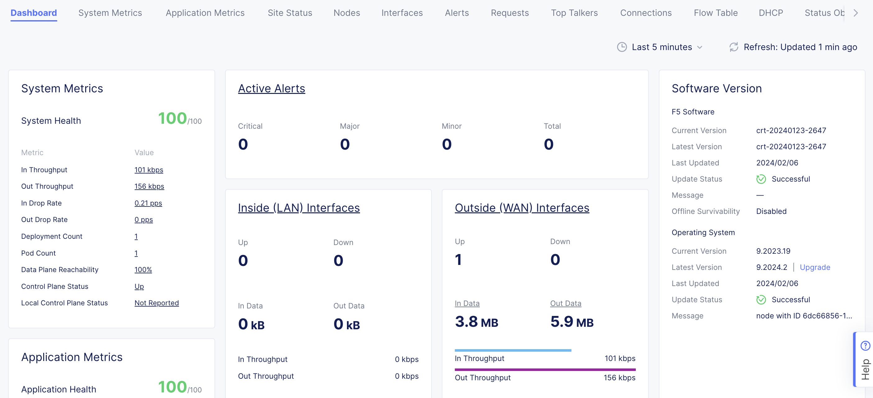
Figure: Site OS Upgrade
- To create an SMG, see the Site Mesh Group guide for more information.
Concepts
API References
On this page:
- Objective
- Customer Edge Node Clustering
- Design
- AWS Orchestration
- VPC Attachments
- TGW Routing Details
- Application Traffic Flow In AWS TGW Site
- East-West Traffic
- North-South Egress Traffic
- North-South Ingress Traffic
- Centralized Security
- Private Connectivity
- Site Status Descriptions
- Prerequisites
- General
- Existing VPC
- Private Connectivity
- Deploy Using Console
- Create AWS TGW Site Object
- Deploy Site
- Additional Steps To Connect Workloads
- Delete VPC Site
- Deploy Site Using Terraform
- Destroy Site
- Next Steps
- Concepts
- API References