Create AWS Site (Orchestrated)
Objective
Important: F5 highly recommends you use the new Secure Mesh Site (v2) workflow for AWS, Azure, and GCP using this guide. This workflow is only recommended when you want F5 Distributed Cloud Services to orchestrate cloud resources needed for Customer Edge (CE) Site deployments in public clouds.
This guide provides instructions on how to create and deploy a Virtual Private Cloud (VPC) site to Amazon Web Services (AWS).
You can deploy a VPC site if the workload you want to secure, connect, or load balance is present on or will be deployed in the same VPC. You may also choose to deploy a VPC site if you want to use the F5® managed Kubernetes offering by creating an App Stack site.
If you want to secure, connect, or load balance workloads across multiple VPCs in an AWS region from a single service VPC, see Create AWS Site with TGW site.
You can deploy an AWS VPC site using one of the following methods:
Deployment Environments
F5® Distributed Cloud supports AWS VPC site creation in both greenfield and brownfield environments. In a greenfield environment, Distributed Cloud Services can automate the creation of a VPC, subnets, route tables, security groups, and other networking features. In a brownfield environment, you can choose existing resources from your VPC or choose to create new resources using the site creation wizard.
Customer Edge Node Clustering
AWS VPC sites can be deployed as a single node or as a three-node site. These nodes host the control processes, data plane processes, and the Internet Protocol Security (IPsec) connections to the Regional Edges (REs). For production deployments, F5 recommends a three-node site as it provides high availability. Additional worker nodes can also be deployed after the site is created for additional capacity for L7 features, like load balancing, WAAP, and more.
Note: Worker nodes are only supported for three-node sites.
AWS VPC Site Deployment Modes
A site can be deployed in three different modes, as explained below. For a generic network topology of a site, see Network Topology of a Site.
Ingress Gateway (One Interface): This mode can provide discovery of services and endpoints reachable from this subnet and deliver it to any other site in the customer tenant. The site can provide TCP or HTTP load balancing and L7 security services for the apps that it discovers on the VPC. This mode can be used for application delivery or IP address overlap use cases. Since this mode functions only as an ingress gateway, it cannot provide L3 connectivity to networks on other sites in the tenant. Also, this mode can provide Secure Kubernetes Gateway (SKG) functionality to Kubernetes clusters deployed on the same VPC.
The CE node is attached to a single subnet called Site Local Outside (SLO), per Availability Zone (AZ), in a VPC. For a three-node cluster, the nodes are distributed across three AZs. The VPC route table associated with SLO must point the default route to the Internet Gateway (IGW). This ensures that the CE can reach the public Internet and open the IPsec connections to the REs. The default configuration is to use an Internet Gateway for this, but NAT Gateway and Virtual Private Gateway are also supported egress gateway options.
A one interface three-node deployment diagram is shown for simplicity.
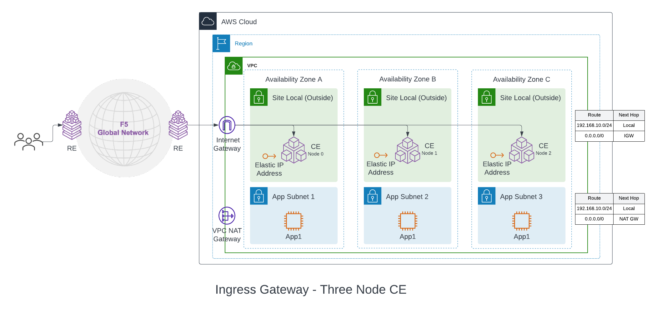
Figure: Ingress Gateway (One Interface) for Three-Node AWS VPC Site
The workloads can be deployed on a private subnet with default route pointing to the NAT Gateway or on a public subnet with default route pointing to the Internet Gateway. These subnets and routes are not auto-created.
Ingress/Egress Gateway (Two Interfaces): In this mode, the CE functions as a default gateway for the VPC. It can provide egress connectivity to the public Internet and L3 connectivity from the instances and subnets on the VPC to subnets on other sites, if a global network is configured. It can also provide the load balancing, Secure Kubernetes Gateway (SKG) and other L7 security features, like ingress gateway mode.
A two interface three-node deployment diagram is shown for simplicity.
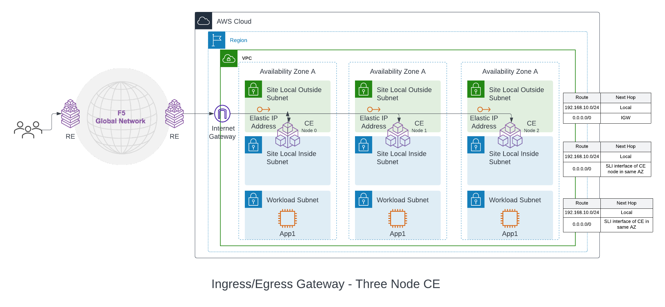
Figure: Ingress/Egress Gateway (Two Interfaces) for Three-Node AWS VPC Site
With this mode, the CE node is attached with at least two interfaces on different subnets per Availability Zone (AZ) on a VPC. One subnet is labeled as Site Local Outside (SLO), and the other as Site Local Inside (SLI). The automation also creates a workload subnet, which can be used to deploy application instances. The VPC SLO route table points to the IGW as the default gateway (NAT gateway and Virtual Private Gateway are also supported). This provides Internet connectivity to the CE nodes. The SLI and the workload route table in the VPC points the default route to the SLI interface of the CE in each AZ.
F5® Distributed Cloud App Stack Cluster (App Stack) (One Interface): This deployment mode must be used if you want to use the site as a F5-managed Kubernetes site to host your applications. The site mode also provides a Secure Kubernetes Gateway (SKG) for the applications deployed on it by discovering the services, providing load balancing and L7 security features like WAAP, Bot Detection, DDoS protection, and more.
A one interface three-node deployment diagram is shown for simplicity.
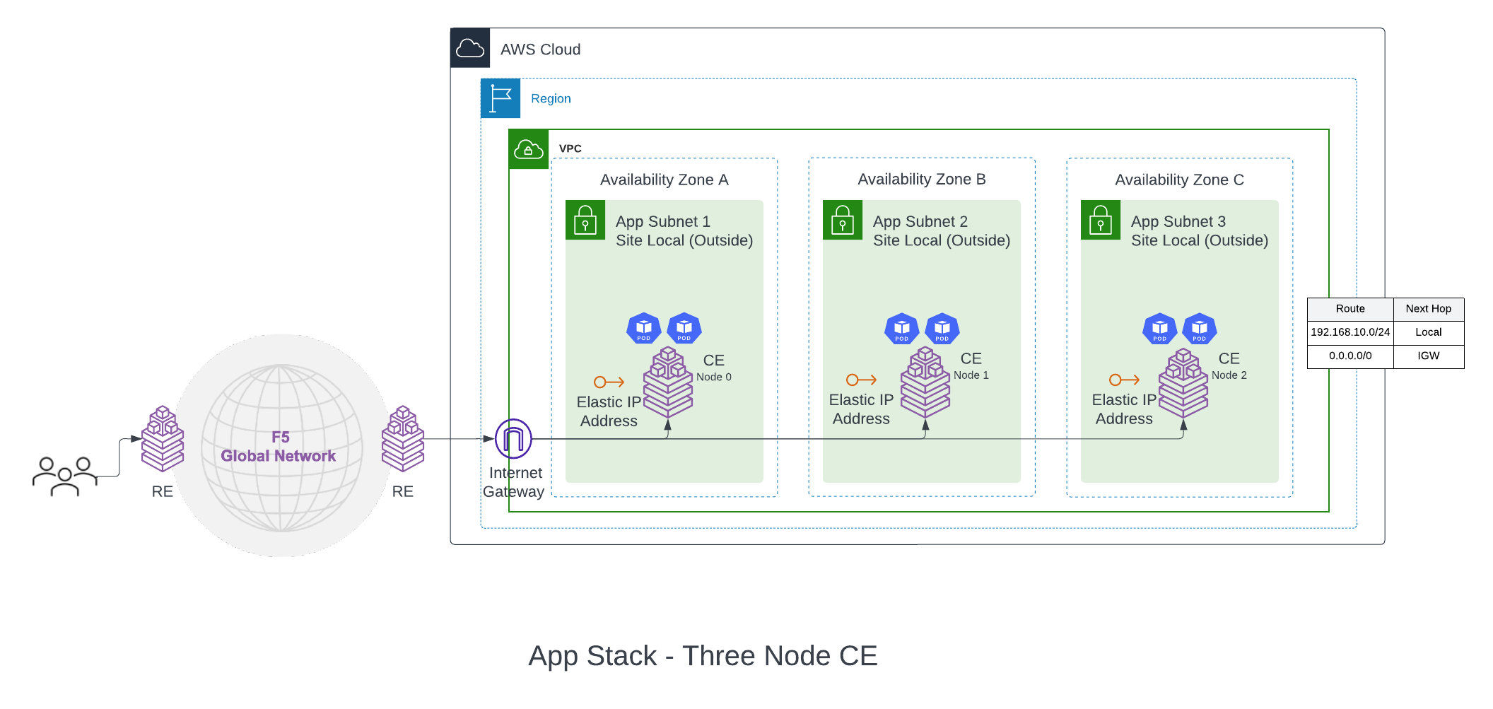
Figure: App Stack Cluster (One Interface) for Three-Node AWS VPC Site
The deployment and configuration of this site mode is identical to Ingress Gateway (One Interface). The difference with this deployment is that the certified hardware Type is aws-byol-voltstack-combo. This configures and deploys an instance type that allows the site to have Kubernetes pods or VMs deployed on the site using Kubernetes API (via managed K8s or virtual K8s endpoints).
Private Connectivity
Private connectivity enables you to privately connect your on-premises data centers to a VPC in which the Distributed Cloud Services sites are hosted so that the traffic does not flow over public Internet. This also gives the option to configure connectivity to REs and site registration to go over the private connection.
Note: The private connectivity option is only supported for
Ingress/Egress Gateway (Two Interfaces)option for a VPC site.
There are two private connectivity options available: AWS Direct Connect (Legacy) and CloudLink.
AWS Direct Connect (Legacy): Distributed Cloud Services can orchestrate AWS Direct Connect to a VPC site. The automation orchestrates the creation of the Virtual Private Gateway and Direct Connect Gateway (DCGW) in addition to the regular site creation. The prerequisite is that the Direct Connect connection is created and managed by the user.
The on-premises data center routes are advertised by the on-premises routers connected to AWS routers via Direct Connect. These routes are propagated to the VGW by the Direct Connect Gateway (DCGW). VGW configures these routes on the VPC route table from where it is learned on the inside network of the site.
There are two supported modes of Direct Connect private Virtual Interface (VIF):
-
Standard VIF: In this mode, the whole Direct Connect connection is used for the site. After site creation, you must associate the VIF on the DCGW using AWS Console and configure BGP peering.
-
Hosted VIF: In this mode, site orchestration accepts the configured list of VIFs delegated from the Direct Connect connection owner account to the hosted VIF acceptor account. You can set a list of VIF IDs to be accepted. The site orchestration automates the association of the VIFs to the DCGW.
CloudLink: A CloudLink allows Distributed Cloud Services to orchestrate an already provisioned direct connection, establish a multi-cloud networking fabric, and then connect, deliver, secure, and operate networks and apps across hybrid environments. For more information, see CloudLink.
Site Status Descriptions
These descriptions provide information for the various stages of site deployment in Distributed Cloud Console. They also provide information to help you troubleshoot errors that may occur during the deployment and registration stages.
PLANNING: Site resources are being planned for creation.
PLAN_INIT_ERRORED: Planning of site resources failed at init stage.
PLAN_ERRORED: Planning of site failed with errors.
PLAN_QUEUED: Planning of site resources queued to be implemented.
APPLIED: Site resources are created, and site is waiting to come online.
APPLY_ERRORED: Creation of site resources failed with errors.
APPLY_INIT_ERRORED: Creation of site resources failed with errors at initial stage.
APPLYING: Site creation is in progress.
APPLY_PLANNING: Site resources are being planned.
APPLY_PLAN_ERRORED: Planning of site failed with errors.
APPLY_QUEUED: Creation of site resources queued to be implemented.
DESTROYED: Site resources are destroyed and site is OFFLINE.
DESTROY_ERRORED: Destroying of site resources failed with errors.
DESTROYING: Destroying of site resources in progress.
DESTROY_QUEUED: Destroying of site resources queued to be destroyed.
GENERATED: Site Object created in F5 Distributed Cloud Console database as per configuration.
TIMED_OUT: Creation/Destroying of site resources is failed with a timeout.
ERRORED: Creation/Destroying of site resources is failed with errors.
PROVISIONING: Site resources are created and waiting for site to come online.
Prerequisites
The following prerequisites apply:
General
-
A Distributed Cloud Services Account. If you do not have an account, see Getting Started with Console.
-
An AWS Account. See Required Access Policies for permissions needed to deploy site. To create a cloud credentials object, see Create Cloud Credentials.
-
Resources required per node:
- vCPUs: Minimum 8 vCPUs.
- Memory: 32 GB RAM.
- Disk storage:
- Minimum 80 GB for Mesh site.
- Minimum 100 GB for App Stack site.
Note: For a full listing of the resources required, see the Customer Edge Site Sizing Reference guide. All the nodes in a given CE Site should have the same resources regarding the compute, memory, and disk storage. When deploying in cloud environments, these nodes should use the same instance flavor.
-
Instance type with Intel x86-based processor. ARM and Mac instances are not supported. Recommended instance types are:
- m5.2xlarge
- m5.4xlarge
-
Allow traffic from and to the Distributed Cloud public IP addresses to your network and allowlist related domain names. See F5 Customer Edge IP Address and Domain Reference for Firewall or Proxy Settings guide for the list of IP addresses and domain names.
-
Internet Control Message Protocol (ICMP) needs to be opened between the CE nodes on the Site Local Outside (SLO) interfaces. This is needed to ensure intra-cluster communication checks.
Important: After you deploy the CE Site, the IP address for the SLO interface cannot be changed. Also, the MAC address cannot be changed.
Existing VPC
VPC ID, subnet IDs and AZ to be used for the deployment.
The existing subnets selected for Site Local Outside, Site Local Inside, and Workload subnets must not have an explicit association with any route tables. New route tables will be created and associated with these subnets. The deployment will fail if the subnets have existing custom route table associations.
Manually Created Site
The configurations below are created by Distributed Cloud Services automation. But for manually created sites using Terraform, you must address the following conditions for the site to get deployed correctly:
-
Security group on the SLO interface must allow outgoing traffic to the internet.
-
UDP port 6080 needs to be opened between all the nodes of the site for inter-node tunnel. See the F5 Customer Edge IP Address and Domain Reference for Firewall or Proxy Settings guide for the complete list of IPs, ports, and URLs that a CE needs to connect with.
Private Connectivity
-
Direct Connect connection.
-
VIF IDs if you are using hosted VIF mode.
Deploy Using Console
AWS VPC site creation using Console is a two-step process:
-
Create a VPC site object on Console, where you provide the necessary configurations using a guided wizard.
-
Deploy site, where you initiate the automation which deploys the site resources on AWS.
Create AWS VPC Site Object
The wizard to create the AWS VPC site object guides you through the steps for required configuration.
Step 1: Start site object creation.
-
Log into Console.
-
From the Console homepage, select
Multi-Cloud Network Connect.
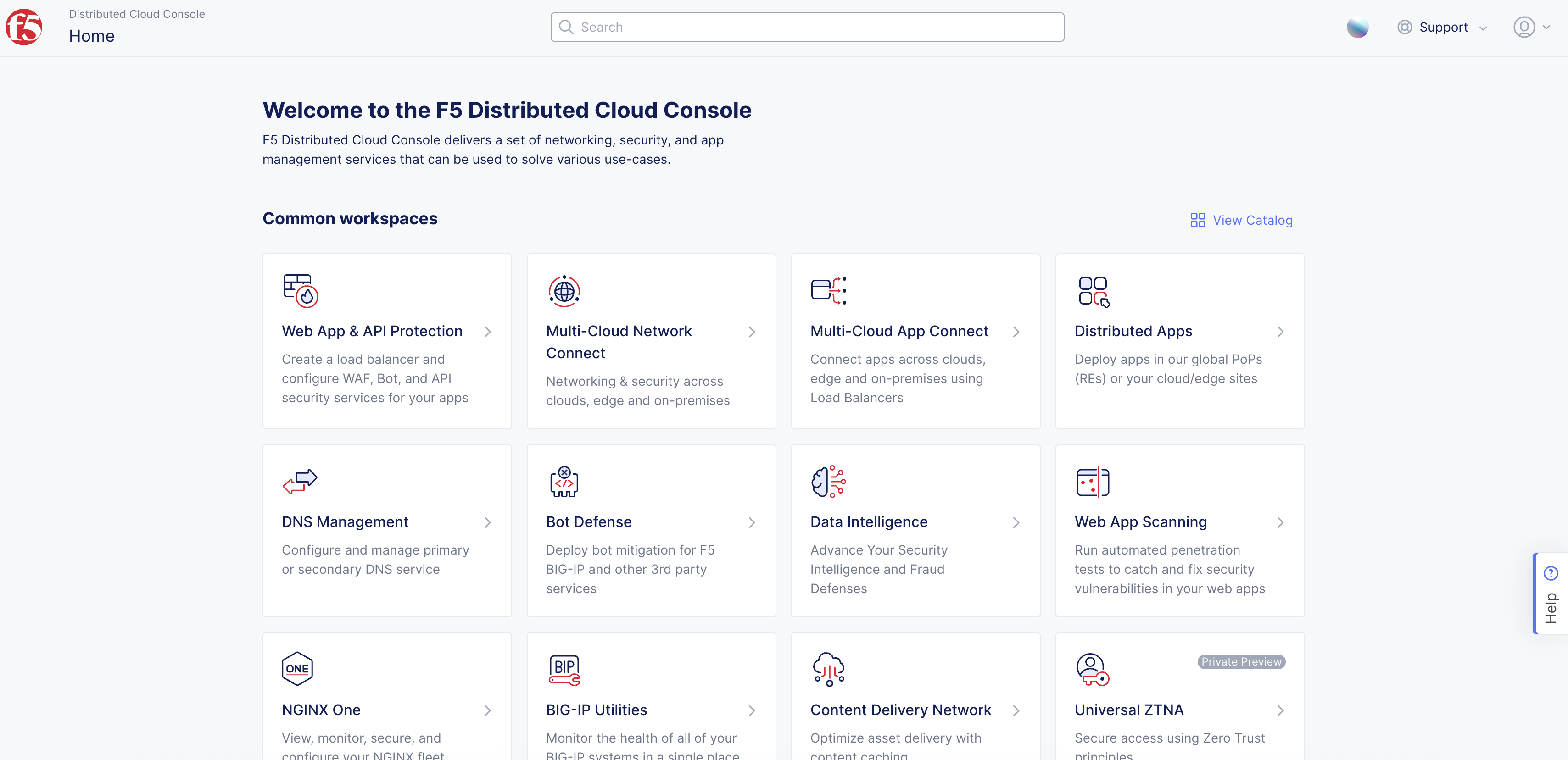
Figure: Console Homepage
-
Click
Manage>Site Management>AWS VPC Sites. -
Click
Add AWS VPC Site.
- Enter
Name, enterLabels, andDescriptionas needed.
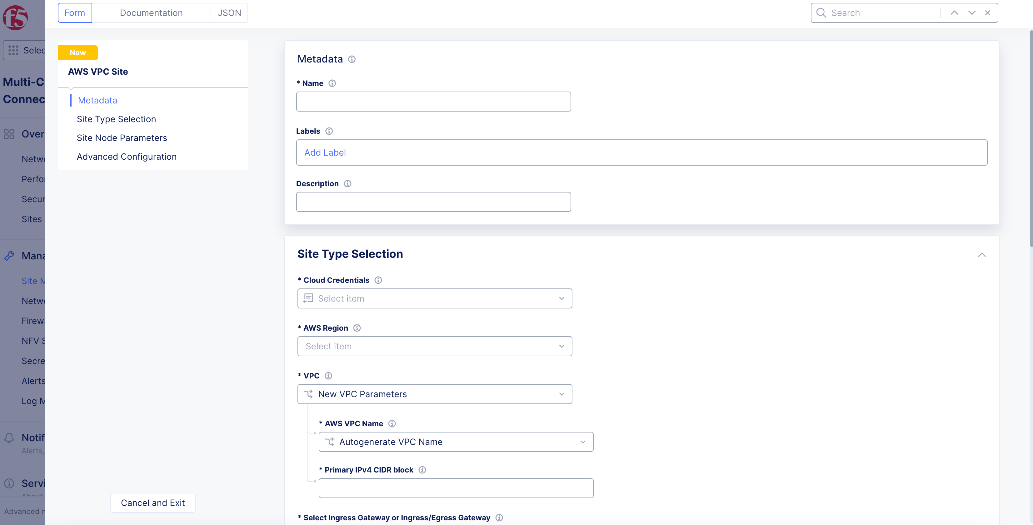
Figure: AWS Site Set Up
Step 2: Select cloud credentials.
Refer to the Cloud Credentials guide for more information. Ensure that the AWS credentials are applied with required access policies per the Policy Requirements document.
- From the
Cloud Credentialsmenu in theSite Type Selectionsection, select an existing AWS credentials object, or clickAdd Itemto load form.
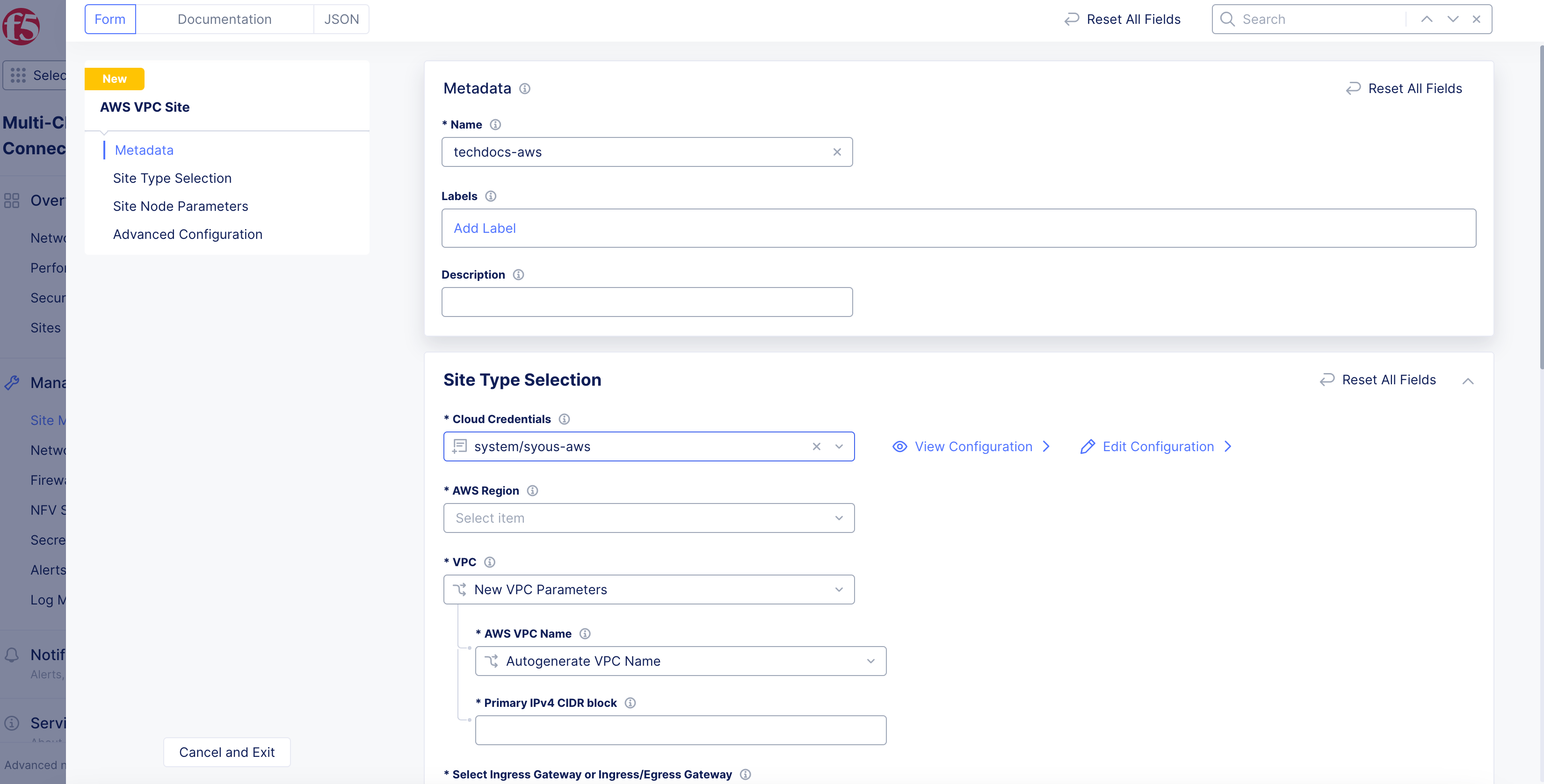
Figure: Deployment Configuration
-
To create new credentials:
-
Enter
Name,Labels, andDescriptionas needed. -
From the
Select Cloud Credential Typemenu, selectAWS Programmatic Access Credentials. -
Enter AWS access ID in the
Access Key IDfield. -
Click
Configurein theSecret Access Keyfield. -
From the
Secret Typemenu:-
Blindfold Secret: Enter secret in theTypebox. -
Clear Secret: Enter secret inClear Secretbox in eitherTextorBase64formats. -
Click
Apply.
-
-
Click
Continueto add the new credentials.
-
Step 3: Configure AWS region and VPC parameters.
-
From the
AWS Regiondrop-down menu, select a region. -
From the
VPCmenu, select an option:-
New VPC Parameters: TheAutogenerate VPC Nameoption is selected by default. -
Existing VPC ID: Enter existing VPC ID inExisting VPC IDbox. If you are using an existing VPC, ensure that you enable theEnable DNS hostnamescheckbox in AWS Management Console (underEdit VPC settings).
-
Note: If you are deploying a new AWS VPC site into an existing VPC, the deployment will fail if the AWS subnet has the EC2 hostname type set to the resource name. In AWS Management Console, ensure that the hostname is in
ip-*format in the subnet settings.
- In the
Primary IPv4 CIDR blockfield, enter the CIDR subnet with slash notation.
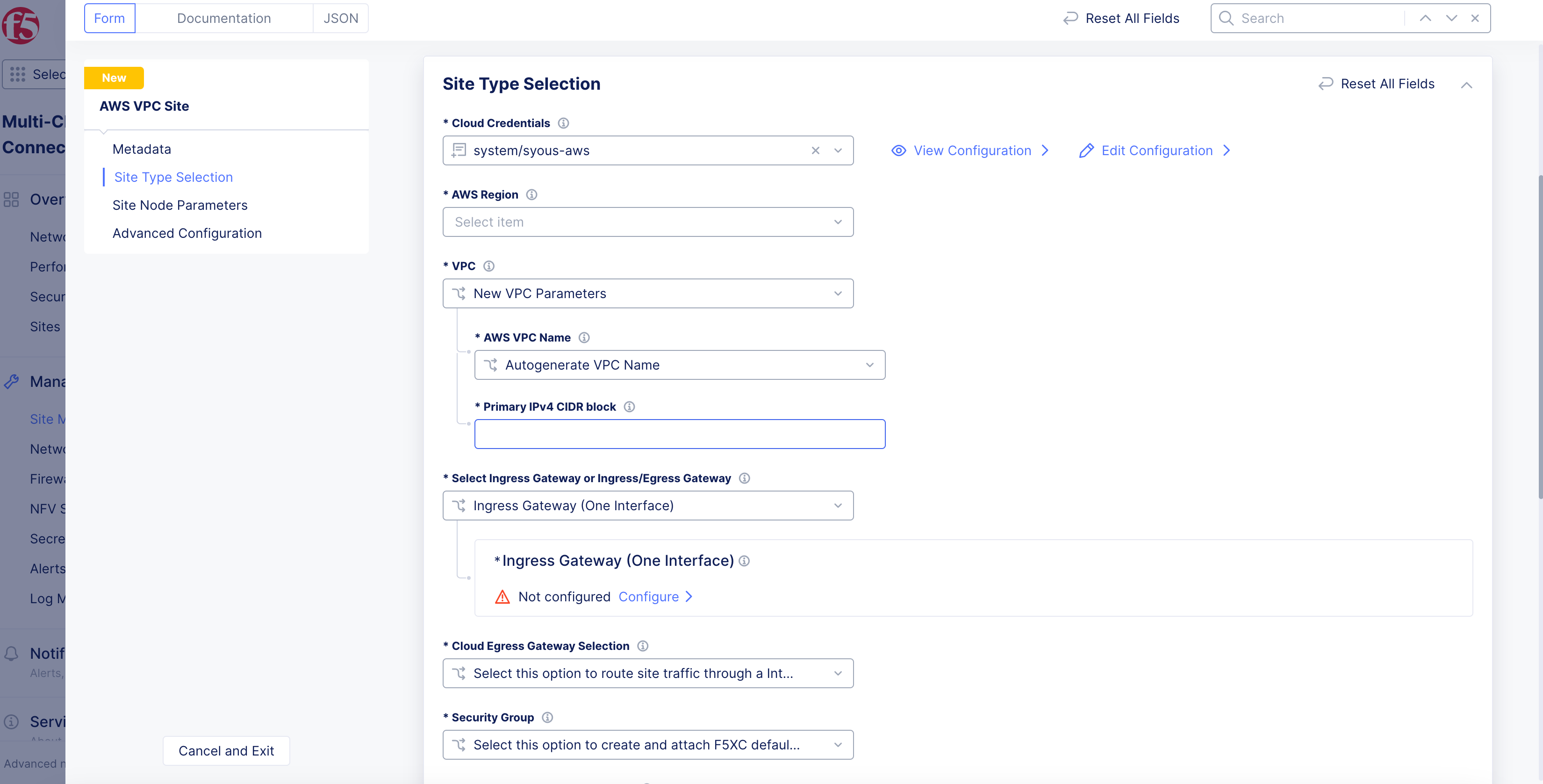
Figure: VPC and Node Type Configuration
Step 4: Set and configure VPC interface.
-
From the
Select Ingress Gateway or Ingress/Egress Gatewaymenu, select an option:-
Ingress Gateway (One Interface) -
Ingress/Egress Gateway (Two Interface) -
App Stack Cluster (One Interface)
-
Ingress Gateway (one interface)
For the Ingress Gateway (One Interface) option:
-
Click
Configure. -
Click
Add Item.
Note: Either a single control node site or a multi-node site with three (3) control nodes is supported. Therefore, if you are adding more than one node, ensure that there are three (3) control nodes for your site. Use
Add Itemto add more control nodes.
-
From the
AWS AZ Namemenu, clickSee Suggestionsto select an option that matches the configuredAWS Region. -
From the
Subnet for local Interfacemenu, selectNew SubnetorExisting Subnet ID.
Note: New subnet creation is not supported for a brownfield deployment with an existing VPC selected for the site. In this case, you must provide an existing subnet ID.
-
Enter subnet address in
IPv4 Subnet, or subnet ID inExisting Subnet ID. -
Confirm subnet is part of the CIDR block set in the previous step.
-
Click
Apply. -
From the
Allowed VIP Port Configurationmenu, configure VIP ports for the load balancer to distribute traffic among all nodes in a multi-node site. See the following options:-
Disable Allowed VIP Port: Ports 80 and 443 will be not allowed. -
Allow HTTP Port: Allows only port 80. -
Allow HTTPS Port: Allows only port 443. -
Allow HTTP & HTTPS Port: Allows only ports 80 and 443. This is populated by default. -
Ports Allowed on Public: Allows specifying custom ports or port ranges. Enter port or port range in thePort Rangesfield.
-
-
In the
Advanced Optionssection, enable theShow Advanced Fieldsoption. -
From the
Performance Modemenu, select an option:-
L7 Enhanced: This option optimizes the site for Layer 7 traffic processing. -
L3 Enhanced: This option optimizes the site for Layer 3 traffic processing. Only choose this option if the site is used for L3 connectivity and not any L7 features. Select whether to use this feature with or without jumbo frames.
-
Note: The
L3 Enhancedfeature works on CE sites with a minimum of 5 cores and a minimum of 3 GB memory.Jumbo frames (Ethernet frames with a larger payload than the Ethernet standard maximum transmission unit of 1,500 bytes) are supported for
L3 Enhanced.If
L3 Enhancedis not enabled on all CE sites in a Site Mesh Group, the MTU configured on the site-to-site tunnel interfaces will not be consistent. Therefore, F5 recommends that you enable L3-focused performance mode on all sites participating in a Site Mesh Group.
- Click
Apply.
Ingress/Egress Gateway (two interfaces)
For the Ingress/Egress Gateway (Two Interface) option:
-
Click
Configure. -
Click
Add Item.
Note: Either a single control node site or a multi-node site with three (3) control nodes is supported. Therefore, if you are adding more than one node, ensure that there are three (3) control nodes for your site. Use
Add Itemto add more control nodes.
-
From the
AWS AZ Namemenu, select an option that matches the configuredAWS Region. -
From the
Workload Subnetmenu, select an option:-
New Subnet: Enter a subnet in theIPv4 Subnetfield. -
Existing Subnet ID: Enter a subnet in theExisting Subnet IDfield.
-
Note: Workload subnet is the network where your application workloads are hosted. For successful routing toward applications running in workload subnet, an inside static route to the workload subnet CIDR needs to be added on the respective site object.
-
From the
Subnet for Outside Interfacemenu, select an option:-
New Subnet: Enter a subnet in theIPv4 Subnetfield. -
Existing Subnet ID: Enter a subnet in theExisting Subnet IDfield.
-
-
From the
Subnet for Inside Interfacemenu, specify the subnet for the node on the inside interface. You can selectAutogenerate Subnetfor automatic assignment orSpecify Subnetfor a custom IPv4 subnet.
Note: New subnet creation is not supported for a brownfield deployment with an existing VPC selected for the site. In this case, you must provide an existing subnet ID.
-
Click
Apply. -
In the
Site Network Firewallsection:- Optionally, add a firewall policy by selecting
Active Firewall PoliciesorActive Enhanced Firewall Policiesfrom theManage Firewall Policymenu. Select an existing firewall policy, or selectAdd Itemto create and apply a firewall policy orConfigurefor an enhanced version.
- Optionally, add a firewall policy by selecting
Note: See the Create Firewall Policy guide for more information.
-
From the
Manage Forward Proxymenu, select an option to use the site as a forward proxy for outgoing requests. This configuration allows you to filter Internet-bound outgoing traffic from the site:-
Disable Forward Proxyif you want clients on-site to directly connect to services on the Internet. All outbound traffic is allowed. -
Enable Forward Proxy with Allow All Policyif you want all outbound traffic to be allowed and need the CE to proxy the outbound connections and SNAT over the SLO IP. -
Enable Forward Proxy and Manage Policiesif you want the CE to proxy traffic for selected TLS domains or HTTP URLs: Select an existing forward proxy policy or selectAdd Itemto create and apply a forward proxy policy.
-
Note: See the Forward Proxy Policies guide for more information.
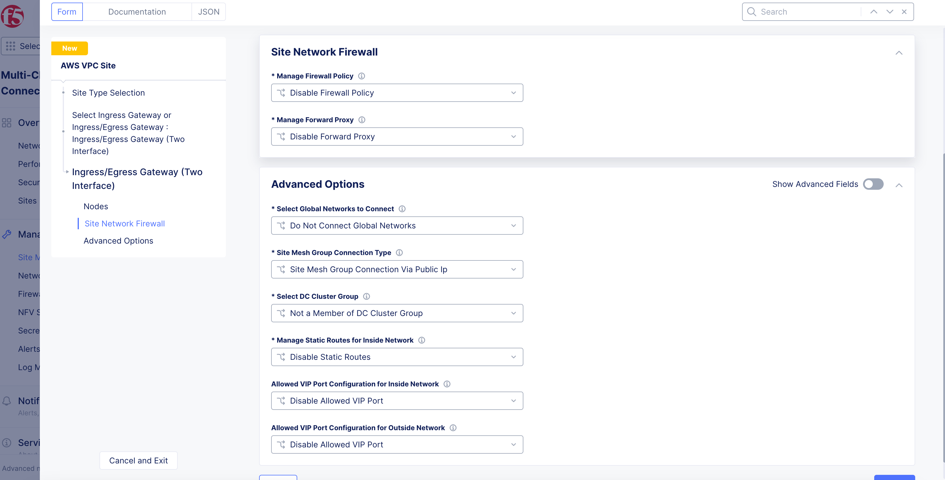
Figure: Network Firewall Configuration for Node
-
Enable
Show Advanced Fieldsin theAdvanced Optionssection. -
Select
Connect Global Networksfrom theSelect Global Networks to Connectmenu, and perform the following:-
Click
Add Item. -
From the
Select Network Connection Typemenu, select an option:-
Select
Direct Site Local Inside to a Global Networkto allow subnets on the site’s VPC and subnets on other sites on the same global network to be routable to each other without NAT. -
Select
Direct Site Local Outside to a Global Networkto allow subnets on the site’s VPC to route to subnets on other sites without NAT, but disable other sites to have a route to the current site’s subnets other than the outside subnet.
-
-
From the
Global Virtual Networkmenu, select an existing global network or create a new network usingAdd Item. See the Virtual Networks guide for more information. -
Click
Apply.
-
-
From the
Site Mesh Group Connection Typemenu, select an option:-
Select
Site Mesh Group Connection via Public IPif other sites in SMG are accessible only over the Internet. -
Select
Site Mesh Group Connection via Private IPif other sites in SMG are accessible over private connectivity.
-
-
From the
Select DC Cluster Groupmenu, select an option to set the site in a DC cluster group:-
Not a Member of DC Cluster Group: Default option. -
Member of DC Cluster Group via Outside Network: Select this option if other sites are reachable via SLO interface. -
Member of DC Cluster Group via Inside Network: Select this option if other sites are reachable via SLI interface.
-
Note: For more information, see the Configure DC Cluster Group guide.
-
From the
Manage Static Routes for Inside Networkmenu, selectManage Static Routes.ClickAdd Itemin theList of Static Routessubsection. Perform one of the following steps:-
Select
Simple Static Routeand then enter a static route in theSimple Static Routefield. Specify the destination ina.b.c.d/mformat. The route is always added on SLI, and the ARP for the destination must resolve from the CE’s SLI. -
Select
Custom Static Routeand then clickConfigure. Perform the following steps:-
In the
Subnetssection, clickAdd Item. Select IPv4 or IPv6 option from theVersionmenu. Enter a prefix and a prefix length for the subnet. ClickApply. You can use theAdd Itemoption to set more subnets. -
In the
Nexthopsection, select a next-hop type from theTypemenu. Select IPv4 or IPv6 from theVersionmenu in theAddresssubsection. Enter an IP address. From theNetwork Interfacemenu, select an option. -
From the
Static Route Labelsfield, select supported labels usingAdd Label. You can select more than one from this list. -
From the
Attributesmenu, select supported attributes from theAttributesmenu. You can select more than one from this list. -
Click
Applyto add the custom route. -
Click
Apply.
-
-
-
Select
Manage Static routesfrom theManage Static Routes for Outside Networkmenu, and clickAdd Item. Follow the same procedure as that of managing the static routes for inside network. -
From the
Allowed VIP Port Configuration for Outside Networkmenu, configure VIP ports for the load balancer to distribute traffic among all nodes in a multi-node site. See the following options:-
Disable Allowed VIP Port: Ports 80 and 443 will be not allowed. -
Allow HTTP Port: Allows only port 80. -
Allow HTTPS Port: Allows only port 443. -
Allow HTTP & HTTPS Port: Allows only ports 80 and 443. This is populated by default. -
Ports Allowed on Public: Allows specifying custom ports or port ranges. Enter port or port range in thePort Rangesfield.
-
-
In the
Allowed VIP Port Configuration for Inside Networkmenu, configure VIP ports for the load balancer to distribute traffic among all nodes in a multi-node site. See the following options:-
Disable Allowed VIP Port: Ports 80 and 443 will be not allowed. -
Allow HTTP Port: Allows only port 80. -
Allow HTTPS Port: Allows only port 443. -
Allow HTTP & HTTPS Port: Allows only ports 80 and 443. This is populated by default. -
Ports Allowed on Public: Allows specifying custom ports or port ranges. Enter port or port range in thePort Rangesfield.
-
-
From the
Performance Modemenu, select an option:-
L7 Enhanced: This option optimizes the site for Layer 7 traffic processing. -
L3 Enhanced: This option optimizes the site for Layer 3 traffic processing. Only choose this option if the site is used for L3 connectivity and not any L7 features. Select whether to use this feature with or without jumbo frames.
-
Note: The
L3 Enhancedfeature works on CE sites with a minimum of 5 cores and a minimum of 3 GB memory.Jumbo frames (Ethernet frames with a larger payload than the Ethernet standard maximum transmission unit of 1,500 bytes) are supported for
L3 Enhanced.If
L3 Enhancedis not enabled on all CE sites in a Site Mesh Group, the MTU configured on the site-to-site tunnel interfaces will not be consistent. Therefore, F5 recommends that you enable L3-focused performance mode on all sites participating in a Site Mesh Group.
- Click
Apply.
App Stack Cluster (one interface)
For the App Stack Cluster (One Interface) option:
-
Click
Configure. -
In the
App Stack Cluster (One Interface) Nodes in AZsection, clickAdd Item. Perform the following:
Note: Either a single control node site or a multi-node site with three (3) control nodes is supported. Therefore, if you are adding more than one node, ensure that there are three (3) control nodes for your site. Use
Add Itemto add more control nodes.
-
From the
AWS AZ Namemenu, select an option that matches the configuredAWS Region. -
Select
New SubnetorExisting Subnet IDfrom theSubnet for local Interfacemenu.
Note: New subnet creation is not supported for a brownfield deployment with an existing VPC selected for the site. In this case, you must provide an existing subnet ID.
-
Enter a subnet address in
IPv4 Subnetor subnet ID inExisting Subnet ID. -
Click
Apply. -
In the
Site Network Firewallsection:- Optionally, add a firewall policy by selecting
Active Firewall PoliciesorActive Enhanced Firewall Policiesfrom theManage Firewall Policymenu. Select an existing firewall policy, or selectAdd Itemto create and apply a firewall policy orConfigurefor an enhanced version.
- Optionally, add a firewall policy by selecting
Note: See the Create Firewall Policy guide for more information.
- Optionally, select
Enable Forward Proxy with Allow All PolicyorEnable Forward Proxy and Manage Policiesfrom theManage Forward Proxymenu. For the latter option, select an existing forward proxy policy, or selectAdd Itemto create and apply a forward proxy policy.
Note: See the Forward Proxy Policies guide for more information.
-
In the
Storage Configurationsection, from theSelect Configuration for Storage Classesmenu, selectAdd Custom Storage Class. -
Click
Add Item. -
In the
Storage Class Namefield, enter a name for the storage class as it will appear in Kubernetes. -
Optionally, enable the
Default Storage Classoption to make this new storage class the default class for all clusters.
Note: By default, a site deployed in AWS supports Amazon Elastic Block Store (EBS).
-
Click
Apply. -
In the
Advanced Optionssection, selectConnect Global Networksfrom theSelect Global Networks to Connectmenu, and perform the following:-
Click
Add Item. -
From the
Select Network Connection Typemenu, select an option:-
Select
Direct Site Local Inside to a Global Networkto allow subnets on the site’s VPC and subnets on other sites on the same global network to be routable to each other without NAT. -
Select
Direct Site Local Outside to a Global Networkto allow subnets on the site’s VPC to route to subnets on other sites without NAT, but disable other sites to have a route to the current site’s subnets other than the outside subnet.
-
-
From the
Global Virtual Networkmenu, select an existing global network or create a new network usingAdd Item. See the Virtual Networks guide for more information. -
Click
Apply. -
To create a new global network, click
Add Itemfrom theGlobal Virtual Networkmenu:-
Complete the form information.
-
Click
Continue. -
Click
Apply.
-
-
From the
Manage Static Routes for Site Local Networkmenu, selectManage Static routes. ClickAdd Itemand perform one of the following steps:-
From the
Static Route Config Modemenu, selectSimple Static Route. Enter a static route inSimple Static Routefield. Specify the destination ina.b.c.d/mformat. The route is always added on SLI, and the ARP for the destination must resolve from the CE’s SLI. -
From the
Static Route Config Modemenu, selectCustom Static Route. ClickConfigure. Perform the following steps:-
In
Subnetssection, clickAdd Item. SelectIPv4 SubnetorIPv6 Subnetfrom theVersionmenu. -
Enter a prefix and prefix length for your subnet.
-
Click
Apply. -
Use the
Add Itemoption to set more subnets.
-
-
In
Nexthopsection, select a next-hop type from theTypemenu. -
Select
IPv4 AddressorIPv6 Addressfrom theVersionmenu. -
Enter an IP address.
-
From the
Network Interfacemenu, select a network interface or selectAdd Itemto create and apply a new network interface. -
From the
Static Route Labelsfield, select supported labels usingAdd Label. You can select more than one from this list. -
From the
Attributesmenu, select supported attributes. You can select more than one from this list. -
Click
Applyto add the custom route. -
Click
Apply.
-
-
-
From the
Site Mesh Group Connection Typemenu, select an option:-
Select
Site Mesh Group Connection via Public IPif other sites in SMG are accessible only over the Internet. -
Select
Site Mesh Group Connection via Private IPif other sites in SMG are accessible over private connectivity.
-
-
From the
Select DC Cluster Groupmenu, select an option to set the site in a DC cluster group:-
Not a Member of DC Cluster Group: Default option. -
Member of DC Cluster Group: Select the DC cluster group from theMember of DC Cluster Group via Outside Networkmenu to connect the site using an outside network.
-
Note: For more information, see the Configure DC Cluster Group guide.
-
From the
Allowed VIP Port Configurationmenu, configure the VIP ports for the load balancer to distribute traffic among all nodes in a multi-node site. See the following options:-
Disable Allowed VIP Port: Ports 80 and 443 will be not allowed. -
Allow HTTP Port: Allows only port 80. -
Allow HTTPS Port: Allows only port 443. -
Allow HTTP & HTTPS Port: Allows only ports 80 and 443. This is populated by default. -
Ports Allowed on Public: Allows specifying custom ports or port ranges. Enter port or port range in thePort Rangesfield.
-
-
From the
Site Local K8s API accessmenu, select an option for API access:-
Select
Disable Site Local K8s API accessif you do not want to access the k8s API for the site directly and instead are using it as one of the sites in virtual Kubernetes (vk8s) and want to access it via vk8s API only. -
Select
Enable Site Local K8s API accessif you want to configure the site for managed K8s and want to access the site’s API endpoint directly. -
From the
Enable Site Local K8s API accessmenu, select an existing managed K8s cluster name or create a new one by clicking onAdd Item. For instructions on K8s cluster creation, see Create K8s Cluster.
-
-
Click
Apply.
Note: The Distributed Cloud Platform supports both mutating and validating webhooks for managed K8s. Webhook support can be enabled in the K8s configuration (Manage > Manage K8s > K8s Clusters). For more information, see Create K8s Cluster in the
Advanced K8s cluster security settingssection.
Step 5: Set the Internet VIP choice.
-
Use the
Advertise VIPs to Internet on Sitedrop-down menu to create a virtual IP address (VIP). See the following options:-
Disable VIP Advertisement to Internet on Siteis selected by default. It disables public VIP creation directly on the site. Instead, the default behavior is to use REs to publish to the Internet. -
Select
Enable VIP Advertisement to Internet on Siteif you want to enable creation of public VIP on the CE site for a load balancer.
-
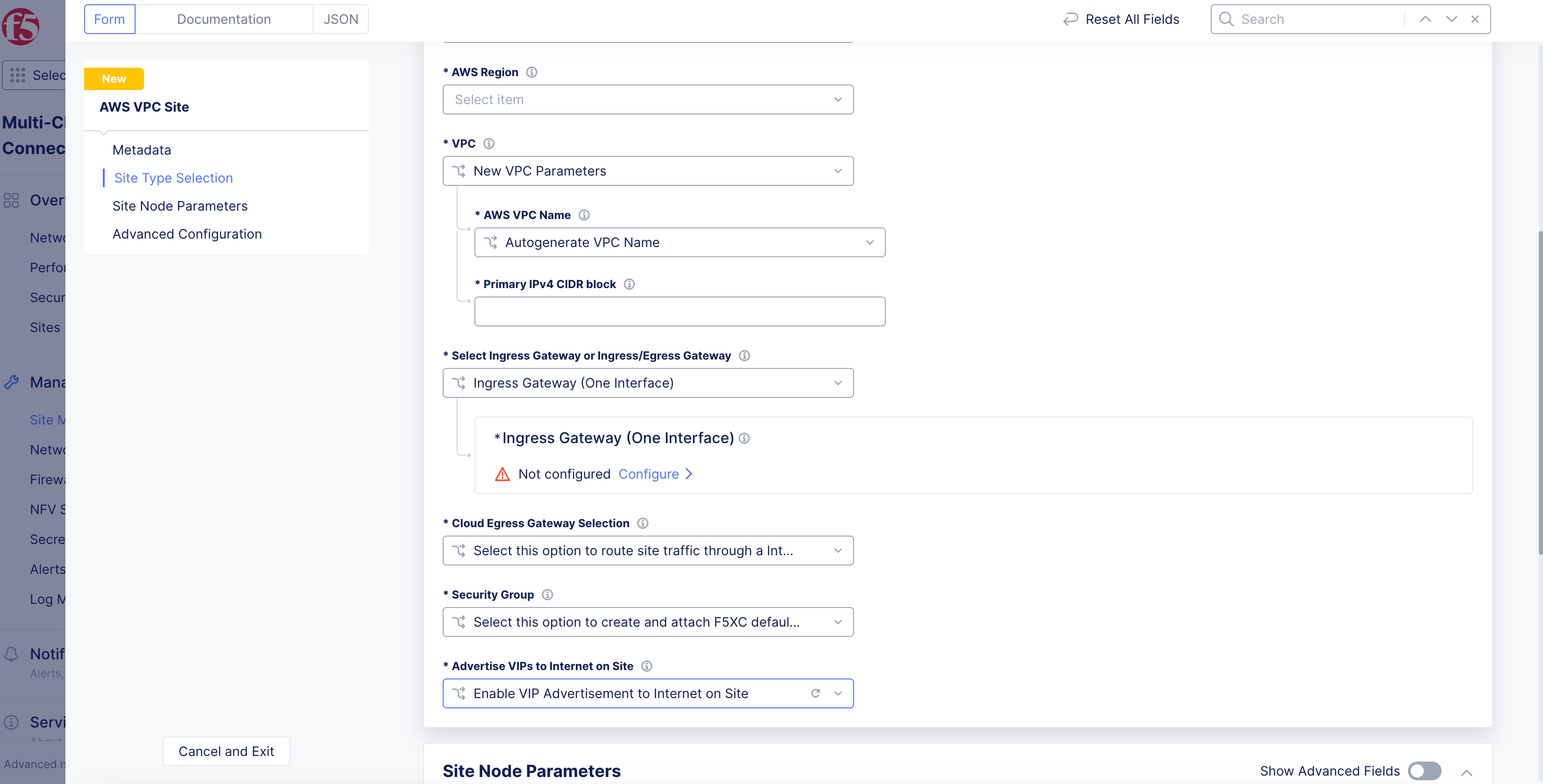
Figure: Internet VIP Configuration
Note: You must enable Internet VIP on the AWS cloud site if you want clients to access the Load Balancer VIP directly from the Internet. Distributed Cloud Console will orchestrate an AWS Internet-facing NLB, causing traffic to be equally distributed to all CE nodes on the site.
You will also need to create an HTTP load balancer with a custom VIP advertisement. Use
SiteorVirtual Siteadvertising withSite Networkset to eitherOutside Network with internet VIPorInside and Outside Network with internet VIP. For more information, see HTTP Load Balancer.
Step 6: Set the routing type for CE VPC.
From the Orchestrate VPC/VNET Routing menu, select an option:
-
F5 Orchestrated Routing: With this option, Distributed Cloud will automatically orchestrate the required routes for the SLO route table toward the public Internet and the SLI route table toward the CE. -
Manual Routing: With this option, Distributed Cloud will not orchestrate or alter any existing route tables or routes within existing VPC subnets. This option is ideal for better integration within existing environments.

Figure: Routing Type Orchestration
Step 7: Set data egress gateway and security group.
-
From the
Cloud Egress Gateway Selectionmenu, select an option to choose the type of egress gateway on the site’s VPC:-
Select this option to route site traffic through a Internet Gateway: Default option. Creates an IGW for the site's VPC. -
Select this option to route site traffic through a Network Address Translation (NAT) Gateway.: This option is for using a NAT gateway for egress use. Provide the NAT gateway’s ID in theExisting NAT Gateway IDfield. -
Select this option to route site traffic through a Virtual Private Gateway.: This option is for using a NAT gateway through VPN for egress use. Provide the VPN gateway’s ID in theExisting Virtual Private Gateway IDfield.
-
-
From the
Security Groupmenu, select the security group option to attach to the SLO/SLI network interfaces. Choose from the following:-
Select this option to create and attach F5XC default security group: This option allows automated security group creation for SLI and SLO interfaces. The auto-created security group allows all traffic on incoming and outgoing directions, and the security is enforced on the CE’s data path. -
Select this option to specify custom security groups for slo and sli interfaces: This option allows existing security groups for site deployment in an existing VPC. You can define security rules for the site on the cloud in addition to security enforcement on the CE’s data path. Check prerequisites for the list of ports and protocols to which CE access is required. You will need to add theOutside Security Group IDandInside Security Group ID.
-
Step 8: Set the site node parameters.
-
In the
Site Node Parameterssection, enable theShow Advanced Fieldsoption. -
From the
AWS Instance Type for Nodemenu, select the instance type according to your CPU and memory requirements usingSee Common Values. -
In the
Public SSH keybox, enter the public key used for SSH purposes. -
Optionally, configure the
Cloud Disk Size(check the prerequisites for minimum size requirements). -
Optionally, add a geographic address and enter the latitude and longitude values. This information is auto-populated based on the AWS region selected previously, but you have the option to override it. The coordinates allow the site to appear at a proper location on the site map, on the dashboard.
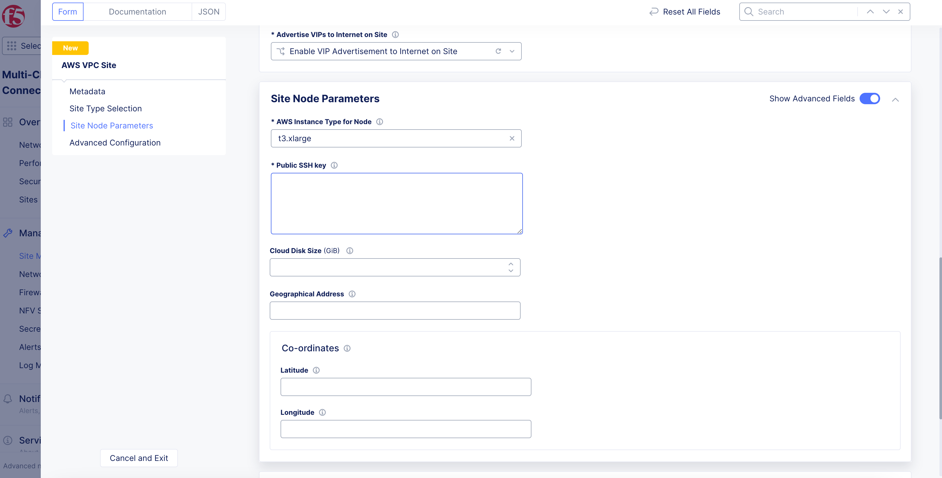
Figure: Site Node Parameters
Step 9: Configure the advanced options.
-
In the
Advanced Configurationsection, enable theShow Advanced Fieldsoption. -
From the
Logs Streamingmenu, selectEnable Logs Streamingto configure the syslog server. KeepDisable Logs Streamingselected if streaming is not required. -
From the
F5XC Software Versionmenu, keep the default selection ofLatest SW Versionor selectF5XC Software Versionto specify an older version number. -
From the
Operating System Versionmenu, keep the default selection ofLatest OS Versionor selectOperating System Versionto specify an older version number. -
From the
Node by Node Upgrademenu, keep the default selection ofEnableto ensure your CE nodes are updated efficiently and in parallel with one another. Configure the corresponding options to suite your requirements. -
For
AWS Tags, useAdd Labelto link sites together using a label. A maximum of thirty (30) tags are supported per instance. -
From the
Desired Worker Nodes Selectionmenu, select an option:-
For the
Desired Worker Nodes Per AZoption, enter the number of worker nodes. The number of worker nodes you set here will be created per the availability zone in which you created nodes. For example, if you configure three nodes in three availability zones, and set theDesired Worker Nodes Per AZbox as 3, then 3 worker nodes per availability zone are created and the total number of worker nodes for this AWS VPC site will be 9. -
For the
Total Number of Worker Nodes for a Siteoption, specify the number of worker nodes if you want automation to automatically place the nodes evenly across the AZs. -
No Worker Nodes: Default option. No worker nodes are selected.
-
-
To enable the offline survivability feature for your site:
- From the
Offline Survivability Modemenu, selectEnable Offline Survivability Modeif the network connection is expected to have intermittent issues causing the site to be isolated from the RE and GC. This mode allows the site to remain functional for 7 days with loss of connectivity. This action will restart all pods for your site. For more information, see the Manage Site Offline Survivability guide.
- From the
Important: The
Enable Offline Survivability Modeoption must be enabled if the site needs to be a part of a Site Mesh Group, with both control plane and data plane mesh enabled.
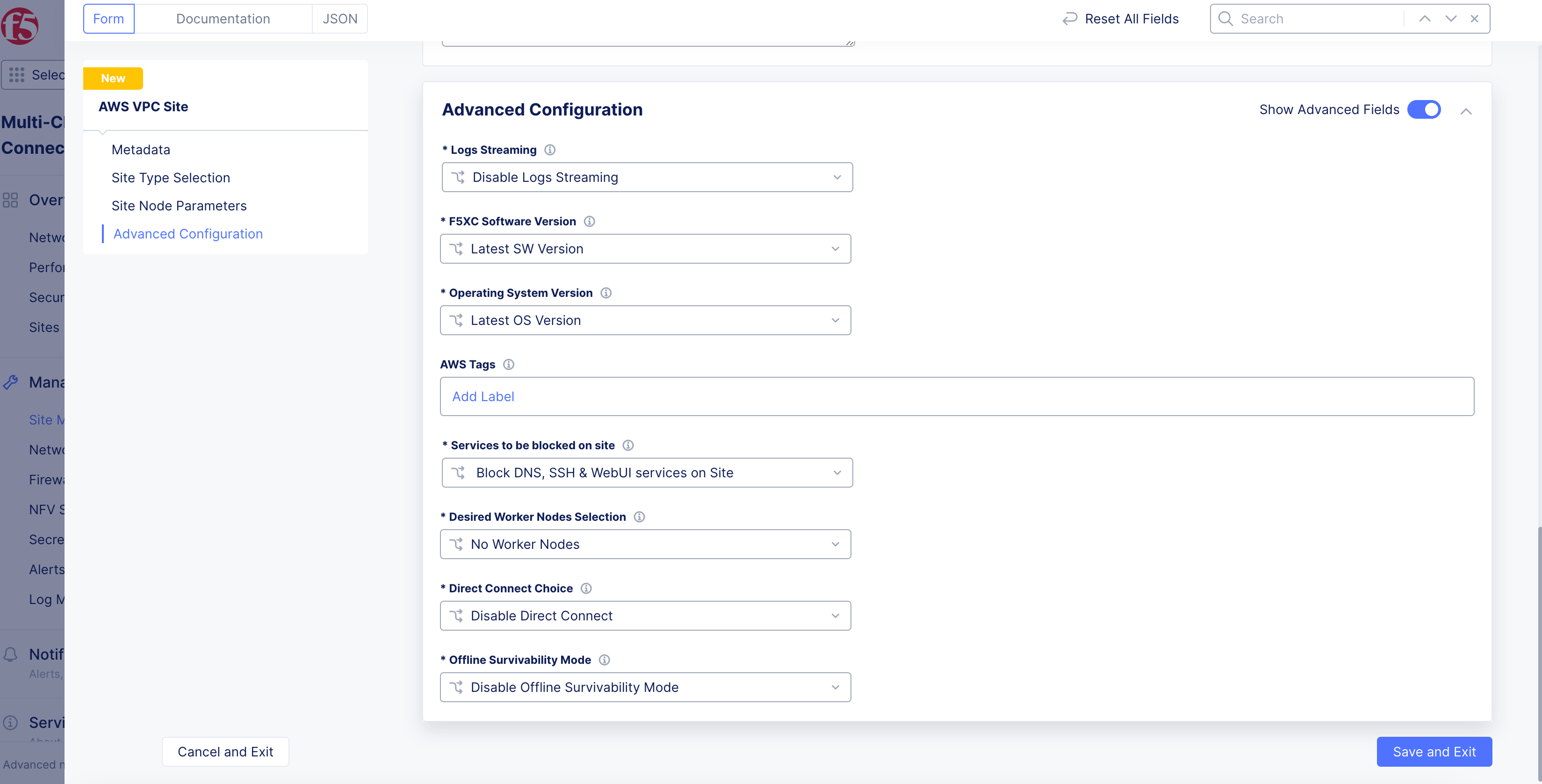
Figure: Advanced Configuration
Step 9.1: Configure blocked services from site.
-
From the
Services to be blocked on sitemenu, select the service you want to be blocked/allowed on the CE node. This configuration only blocks access to the services running on the CE nodes and not to the services to which the CE is acting as a load balancer or a default gateway. See the following options:-
Block DNS, SSH & WebUI services on Site: Default option. -
Allow access to DNS, SSH & WebUI services on Site: Select this option to allow incoming traffic to these services. -
Custom Blocked Services Configuration: Select this option and clickAdd Itemto block specific services. Select the service to block (DNS or SSH) on the SLO or SLI network from theBlocked Services Value Typemenu.
-
Step 10: Optionally, configure private link or Direct Connect.
You can configure these options under the Advanced Configuration section.
-
In the
Advanced Configurationsection, enable theShow Advanced Fieldsoption. -
From the
Private Connectivity To Sitedrop-down menu, select an option:-
Disable Private Connectivity: Default option that allows a site to connect to other sites and the RE over the public Internet. -
Enable Private Connectivity: Enables a private link to your cloud site using CloudLink. For more information, see the CloudLink guide. -
Enable Direct Connect(Legacy): ClickView Configurationto configure AWS Direct Connect for your site.
-
Direct Connect (Legacy)
-
To view and change the default settings:
-
Click
View Configuration. -
From the
AWS Direct Connect VIF Configurationdrop-down menu, select an option for the Virtual Interface (VIF):-
Hosted VIF mode: With this mode, F5 will provision an AWS Direct Connect Gateway and a Virtual Private Gateway. The hosted VIP you provide will be automatically associated and will set up BGP peering. -
Standard VIF mode: With this mode, F5 will provision an AWS Direct Connect Gateway and a Virtual Private Gateway, a user-associated VIP, and will set up BGP peering.
-
-
For the
Hosted VIF modeoption:-
Click
Add Item. -
Enter a VIF ID.
-
Select the
Region of the VIF.
-
-
Click
Apply. -
From the
Site Registration & Connectivity to REmenu, select how the tunneling will traffic data between site and regional edge (RE). If you select the AWS option, provide the CloudLink ADN name. -
From the
ASN Configurationmenu, select whether to assign a custom autonomous system number (ASN) or use the default option. -
Click
Apply.
-
Step 11: Complete the site object creation.
New VPC Site
Click Add AWS VPC Site to complete creating the site. The Status field for the site object displays Validation in progress. After validation, the field displays Validation Succeeded.
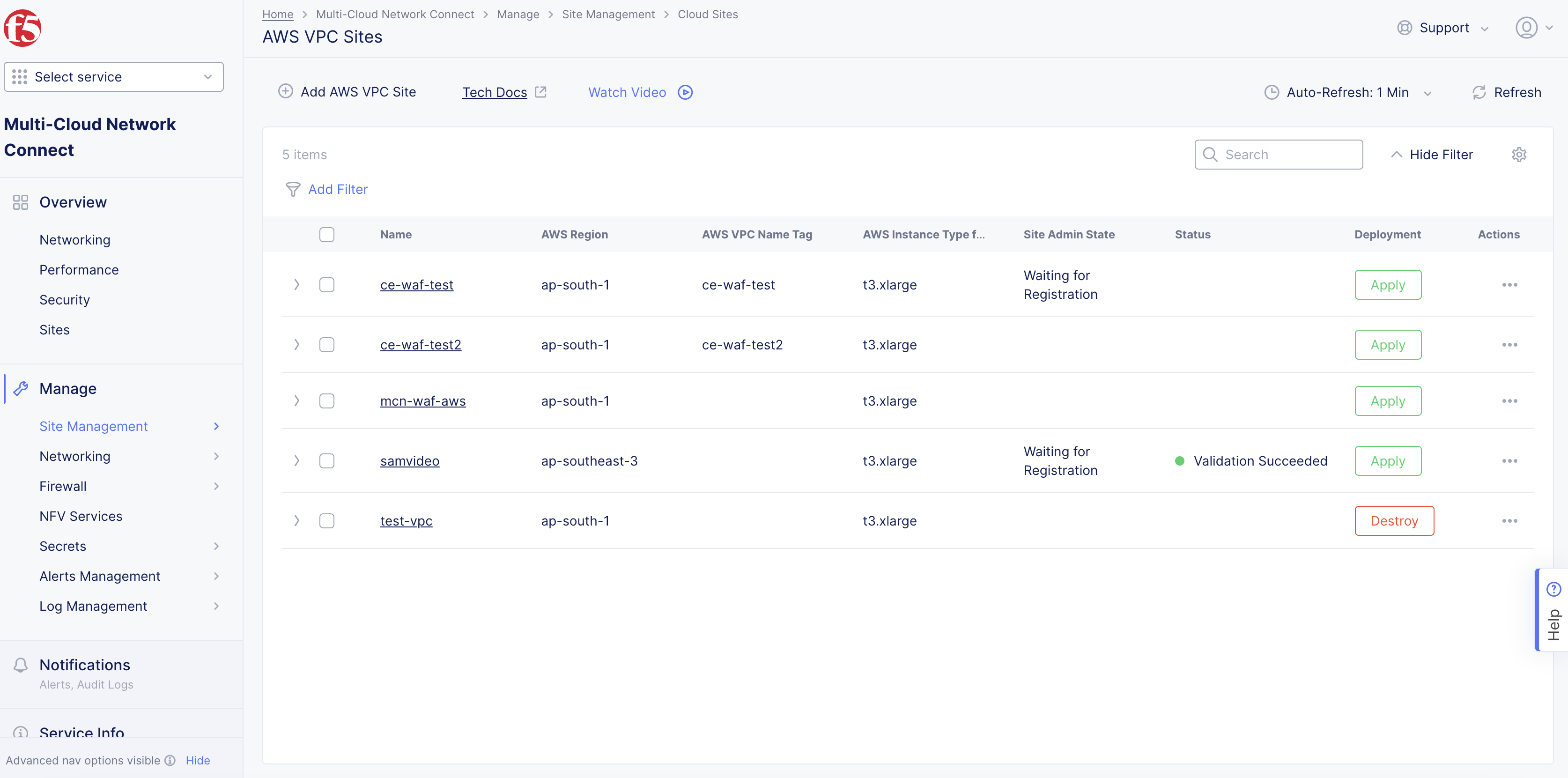
Figure: AWS VPC Object Generated
Existing VPC Site
If you used an existing VPC, Console will validate whether certain existing objects are available and valid. This provides current information to help troubleshoot and fix any potential issues without having to wait until the full site deployment process completes.
After you click Save AWS VPC Site, the validation process begins and is displayed as Validation in progress.
If the site deployment validation failed, a message with Validation Failed will be displayed. Click on the tooltip to display a popup message with the error.
If the site deployment validation succeeded, a message with Validation Succeeded will be displayed.
Note: The
QUEUEDstate references site status action that is in process. The site status will remain inQUEUEDstate until the backend service is ready to executeApply/Plan/Destroycommands. The site status (under theStatuscolumn) is updated on the Console once the execution begins. After a maximum duration of 15 minutes, the site will stay in theQUEUEDstate until the status times out after which a new state is set asPROVISION_TIMEOUT.
Deploy Site
Creating the AWS site VPC object in Console generates the Terraform parameters.
Step 1: Deploy site.
-
Navigate to the AWS VPC object by clicking
Manage>Site Management>AWS VPC Sites. -
Find your AWS VPC object and click
Applyunder theStatuscolumn. TheStatuscolumn for the site object changes first toQueuedand then toApplying.
Figure: AWS VPC Object Apply
Note: Optionally, you can perform Terraform plan activity before the deployment. Find your AWS VPC site object and select
...>Plan (Optional)to start the action of Terraform plan. This creates the execution plan for Terraform.
- Wait for the status to change to
Applied.
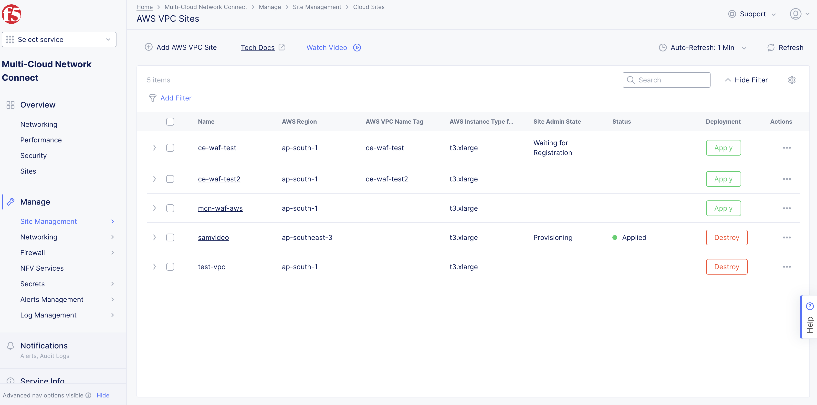
Figure: AWS VPC Object Applied
-
To check the status for the apply action, click
...>Terraform Parametersfor site object, and select theApply Statustab. -
To debug or to run any terminal commands, use SSH to log in to the node with username
cloud-userand your private key.
Note: For ingress/App Stack sites: When you update worker nodes for a site object, scaling happens automatically. For ingress/egress sites: When you update worker nodes for a site object, the Terraform
Applybutton is enabled. ClickApply.
Step 2: Confirm site deployed and online.
-
Navigate to
Multi-Cloud Network Connect>Overview>Infrastructure>Sites. -
Verify status is
Online. It takes a few minutes for the site to deploy and status to change toOnline.
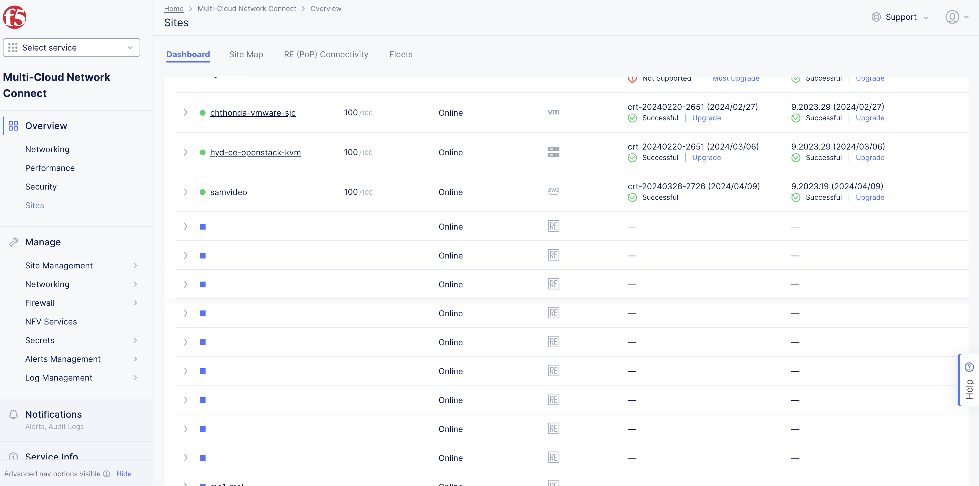
Figure: Site Status Online
Delete VPC Site
You have two options when deleting a site in Console. You delete the site entirely, with all its resources and configuration. Or you can simply delete the site, its resources, but maintain the existing configuration (so that it can be re-applied at a later time).
Note: Deleting the VPC object deletes the sites, nodes, the VPC, and other objects created in the cloud for the site. This action also removes the site object from Console and cannot be undone.
Destroying a site deployed on an existing VPC will leave the AWS subnets used for Site Local Outside, Site Local Inside, and Workload subnets without any explicit route associations.
Delete Site Completely
-
Navigate to
Manage>Site Management>AWS VPC Sites. -
Locate the site object.
-
Select
...>Delete. -
Click
Deletein pop-up confirmation window. In case the delete operation does not remove the object and returns any error, check the error from the status, fix the error, and re-attempt the delete operation. If the problem persists, contact technical support. You can check the status using the...>Terraform Parameters>Apply statusoption.
Delete Site but Maintain Configuration
-
Navigate to
Manage>Site Management>AWS VPC Sites. -
Locate the site object.
-
Click
Destroyfor your site. Alternately, click...>Destroy. -
In the pop-up window, type
DELETE. -
Click
Destroyto confirm the action. On successful operation, the site status will showDestroyedand theApplybutton will appear on the row of your site. This can be used to create the site again at later time, if required. The site object is no longer required and can be removed from Console by clickingDeletein theActionsmenu for the site.
Deploy Using Terraform
You can deploy an F5 Distributed Cloud CE site using Terraform. See Deploy AWS VPC Site with Terraform guide for detailed steps.
Next Steps
After you have successfully deployed your site, you can choose to upgrade it or create a site mesh group (SMG).
- To update your site to the latest OS version, click
Upgradeunder theSoftware Versiontile on the dashboard.
Note: Site upgrades may take up to 10 minutes per site node. Once site upgrade has completed, you must apply the Terraform parameters to site via
Actionmenu on cloud site management page.
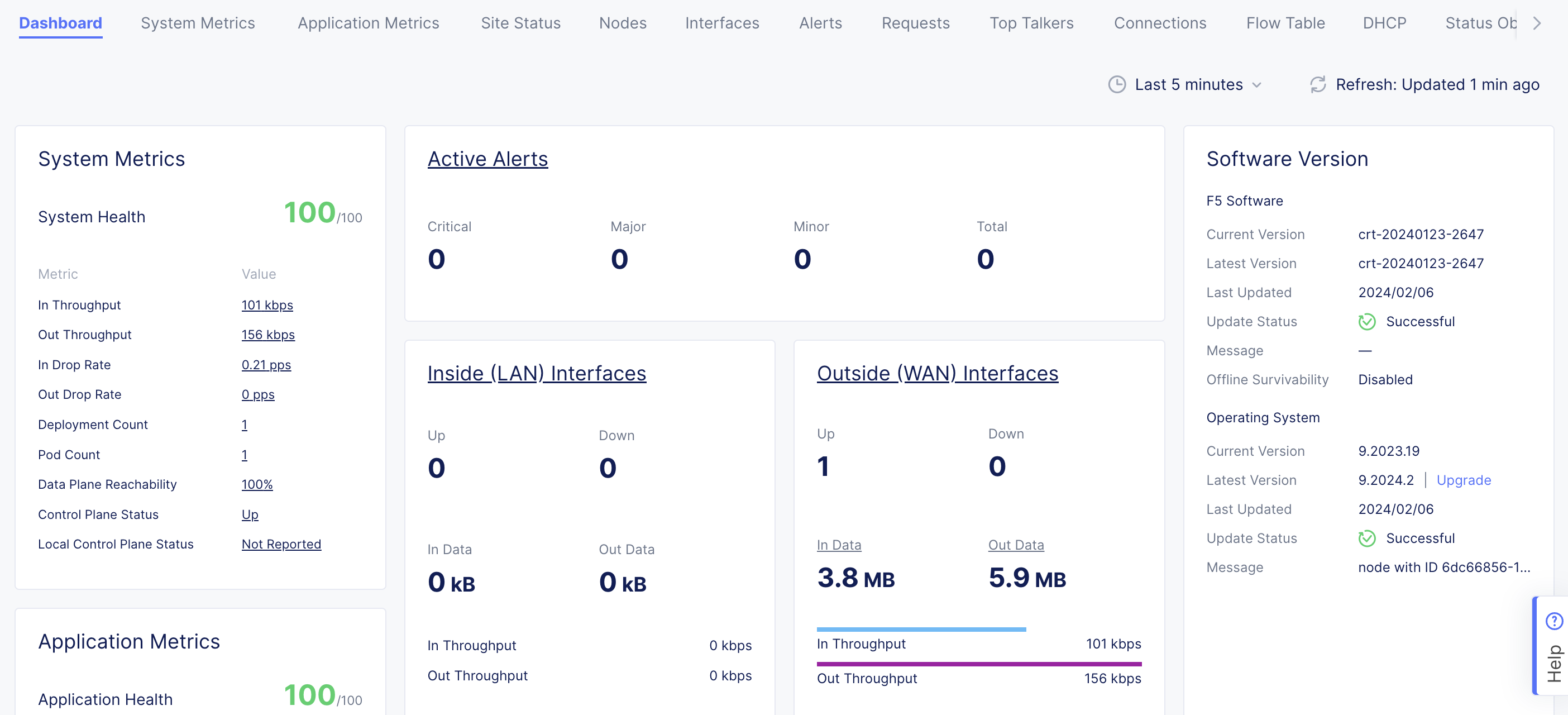
Figure: Site OS Upgrade
- To create an SMG, see the Site Mesh Group guide for more information.
Concepts
API References
On this page:
- Objective
- Deployment Environments
- Customer Edge Node Clustering
- AWS VPC Site Deployment Modes
- Private Connectivity
- Site Status Descriptions
- Prerequisites
- General
- Existing VPC
- Manually Created Site
- Private Connectivity
- Deploy Using Console
- Create AWS VPC Site Object
- Deploy Site
- Delete VPC Site
- Deploy Using Terraform
- Next Steps
- Concepts
- API References