Create Fleet
Objective
This guide provides instructions on how to create a Fleet using F5® Distributed Cloud Console (Console). See Fleet for more information.
Important: This is a legacy workflow for deploying Customer Edge (CE) sites and is not recommended to use. A new workflow for deploying Customer Edge (CE) sites has been introduced and is now Generally Available (GA). It is recommended that you use the new Secure Mesh Site (v2) workflow for all Customer Edge deployments. You can find this new workflow here.
Deprecation of this legacy workflow will be announced soon.
Fleet is used to configure infrastructure components (like nodes) in one or more F5® Distributed Cloud Services Customer Edge (CE) sites homogeneously. Fleet configuration includes the following information:
-
Software image release to be deployed on the Fleet
-
Virtual networks
-
List of interface and devices to be configured on every node
-
Connections between the virtual networks
-
Security policies applied in the Site
Associating Fleet with Site
Fleet has a field called fleet_label. When a Fleet object is created, the system automatically creates a known_label ves.io/fleet=. The known_label is created in the Shared namespace for the tenant. A site is made a "member of Fleet" when this known_label is added to the site. A site can have at most one known_label of type ves.io/fleet and hence belongs to exactly one Fleet at any given time.
When a Site becomes a member of a Fleet, all nodes in the site also become "members of that Fleet". The Fleet configuration is applied on all nodes that are members of the Fleet.
Note: You cannot add a fleet label to the following type of sites:
- F5® Distributed Cloud App Stack (App Stack) Site
- AWS VPC Site
- AWS TGW Site
- Azure VNet Site
- GCP VPC Site
Fleet and Virtual Site
Both Fleet and Virtual Site select a list of sites based on labels. But there is a major difference between Virtual Site and Fleet. Virtual sites are intersecting subsets of available sites. Fleet is a non-intersecting subset of available sites compared to other Fleets. As a result, at most one Fleet configuration is applied on a site. Also, while a Virtual Site selects sites based on their labels (via the Virtual Site configured label selectors), the Fleet must be applied in the sites that you want to be part of that Fleet (it does not select them).
However, to enable other features like monitoring, deploying applications or jobs on sites represented by Fleet, the system will automatically create a Virtual Site in the Shared namespace representing all sites in a Fleet.
Using the instructions provided in this guide, you will be able to create a Fleet, with all its elements, and apply to your site, making it part of this Fleet.
Prerequisites
-
A Distributed Cloud Services Account is required. If you do not have an account, see Getting Started with Console.
-
One or more sites.
Create Fleet
You can create and configure a Fleet label to apply to your sites, to perform software and operating system upgrades as well as other administrative tasks.
Step 1: Start creating Fleet in Console.
-
Log into Console.
-
Click
Multi-Cloud Network Connect.
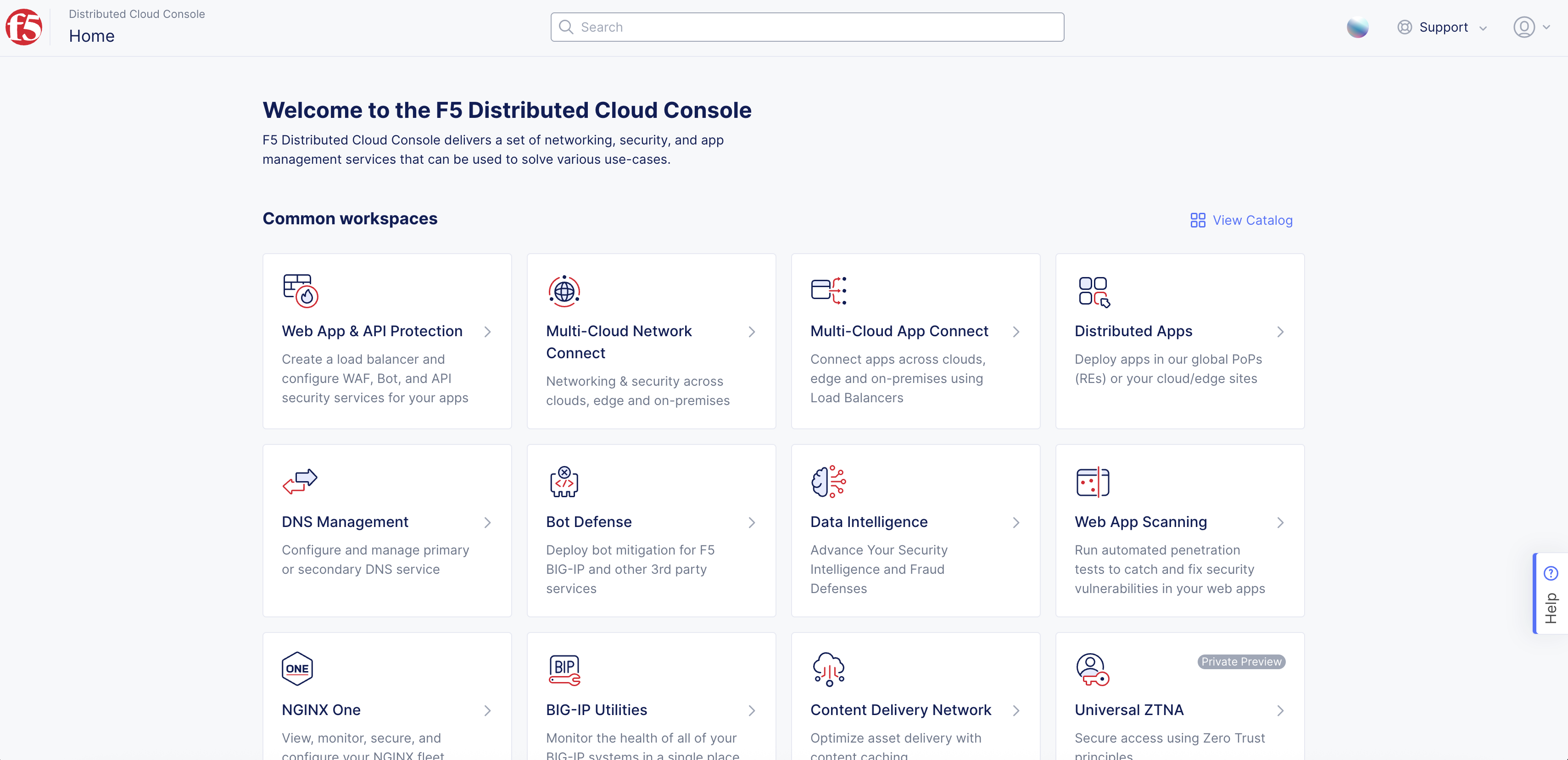
Figure: Console Homepage
-
Click
Manage>Site Management>Fleets. -
Click
Add Fleet.
Step 2: Add your Fleet name and metadata.
-
In the
Metadatasection, enter a mandatory Fleet name in theNamefield. -
Optionally, select a label and enter a short description.
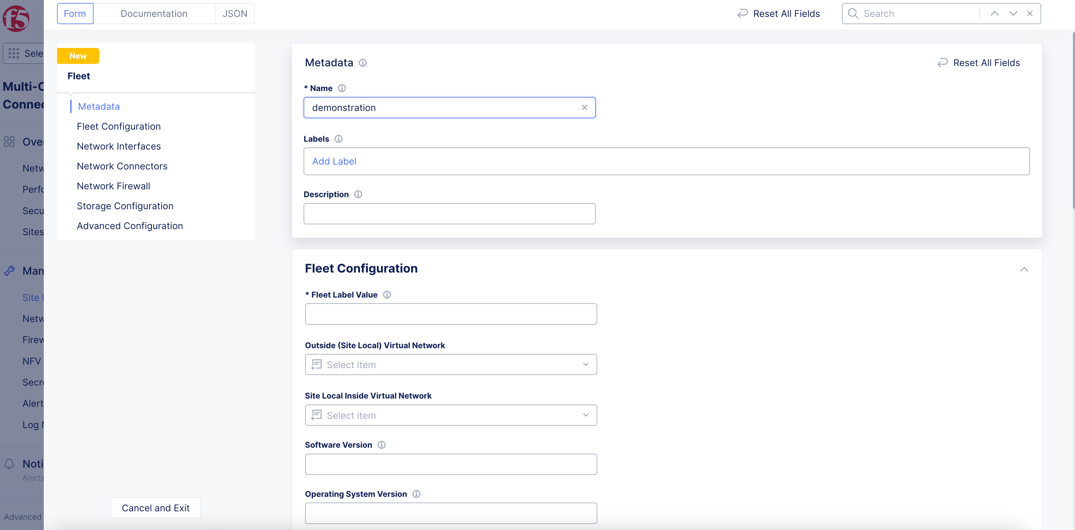
Figure: Add Fleet Name
Step 3: Configure your Fleet label, virtual networks, and software versions.
-
In the
Fleet Configurationsection, enter a mandatory value for the Fleet label in theFleet Label Valuefield. -
Configure the following optional fields:
-
Select an outside virtual network from the
Outside (Site Local) Virtual Networkmenu. To create a new network, clickAdd Item. In the page that appears, configure the fields. After you finish, clickContinue. -
Select an inside virtual network from the
Site Local Inside Virtual Networkmenu. To create a new network, clickAdd Item. In the page that appears, configure the fields. After you finish, clickContinue. -
In the
Software Versionfield, enter a software version. -
In the
Operating System Versionfield, enter an operating system version.
-
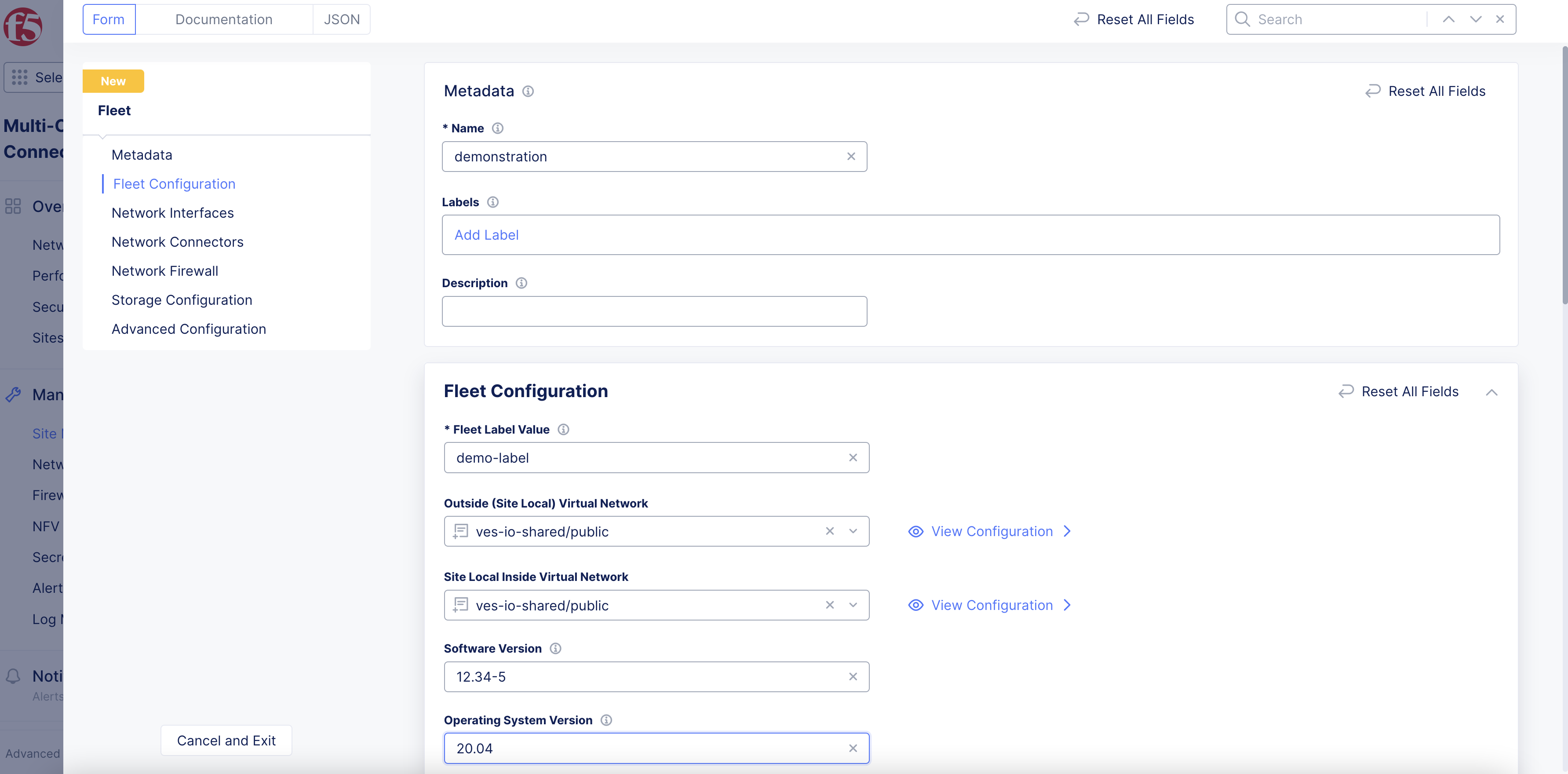
Figure: Fleet Configuration
Step 4: Select or create network interfaces for the sites in your Fleet.
-
To add and configure a new bond device:
-
From the
Select Bond Configurationmenu, select if you want to configure a new bond interface withConfigure Bond Interfaces. The option forNo Bond Devicesis set by default. -
Click
Add Item. -
From the
Bond Device Namemenu, clickSee Common Values. Select a value from the list displayed or type a custom name. -
In the
Member Ethernet Devicessection, clickSee Suggestionsfrom theMember Ethernet Devicesmenu. Select a value from the options displayed or type a custom name. You can add more member devices using theAdd Itemoption. -
From the
Select Bond Modemenu, select how the bonding occurs. If you selectLACP (802.3ad), enter a packet interval value in theLACP Packet Intervalfield. -
Click
Apply.
-
-
Perform the following to configure non-bond interfaces:
-
From the
Select Interface Configmenu, select your interface configuration from the options available. TheDefault Interface Configoption does not require more configuration. -
If you select
List of Interfaces, select as many interfaces as needed. To add more, clickAdd Item. -
If you select
Legacy Device List, clickAdd Itemand perform the following:-
Enter the required information for
Device Name,Device Owner,Device InstanceandUse. -
Click
Apply.
-
-
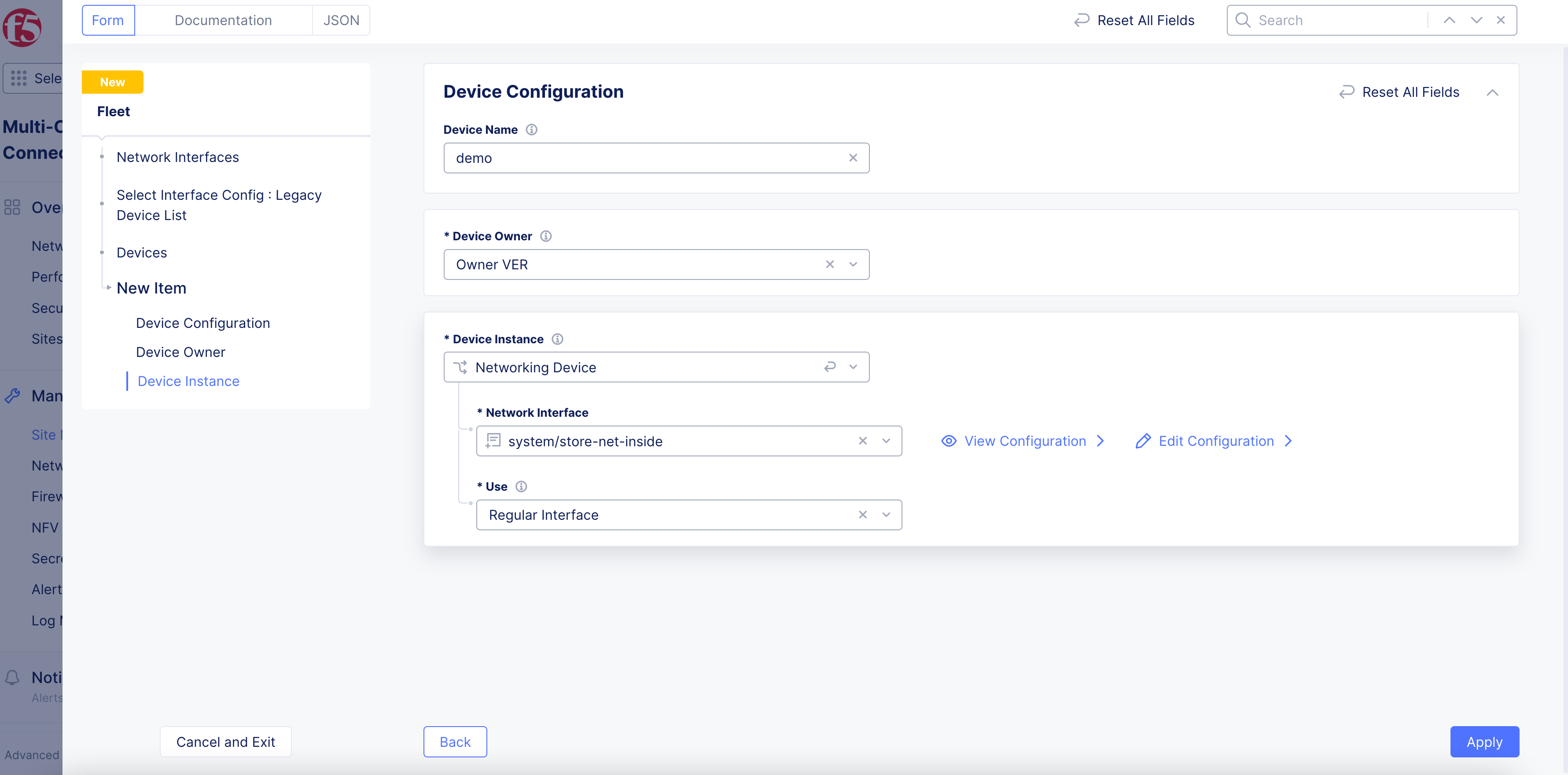
Figure: Fleet Network Interface
Step 5: Configure network connectors.
-
To select an existing network connector:
-
In the
Network Connectorssection, clickAdd Item. -
From the list that appears, find and select the network connector, and then click
Select Network Connector.
-
-
To create a new connector, click
Add Item.
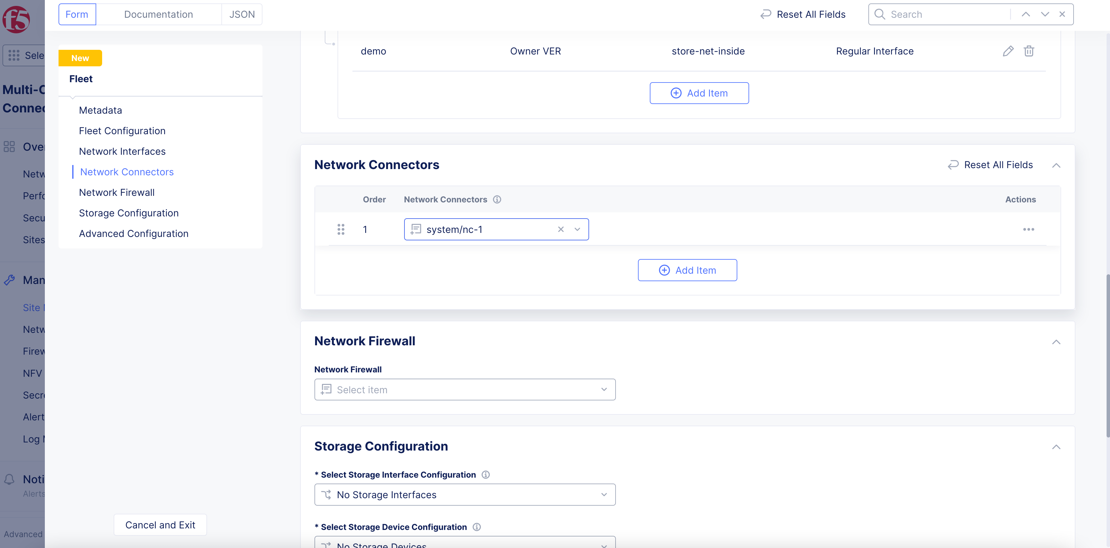
Figure: Fleet Network Connector
- Complete the configuration using the instructions provided at Network Connectors.
Step 6: Select or create a network firewall for your Fleet.
The Network Firewall object is used to configure network policies, forward and reverse proxies, and Distributed Cloud Services Fast Access Control Lists (ACLs). After this object is configured, it is applied to all sites within a Fleet and any associated virtual networks.
-
To select an existing network firewall, use the
Network Firewalldrop-down menu to search for the network firewall. -
To create a new network firewall, click
Add Item.
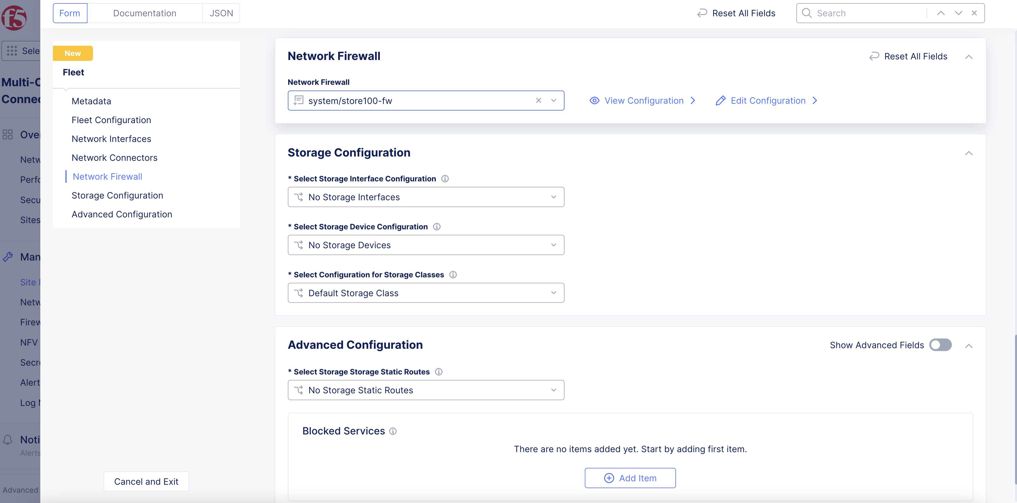
Figure: Fleet Network Firewall
- Complete the configuration using the instructions provided at Network Firewall.
Step 7: Configure Fleet storage.
In the Storage Configuration section, configure storage for your Fleet of sites using the instructions provided at Configure Storage in Fleet.
Step 8: Configure static routes and other advanced settings.
The settings in the Advanced Configuration section enable you to configure more options for your Fleet.
Step 8.1: Configure new static route.
-
To configure a new static route:
-
From the
Select Storage Static Routesmenu, clickList of Storage Static Routes. -
Click
Add Itemto display the form.
-
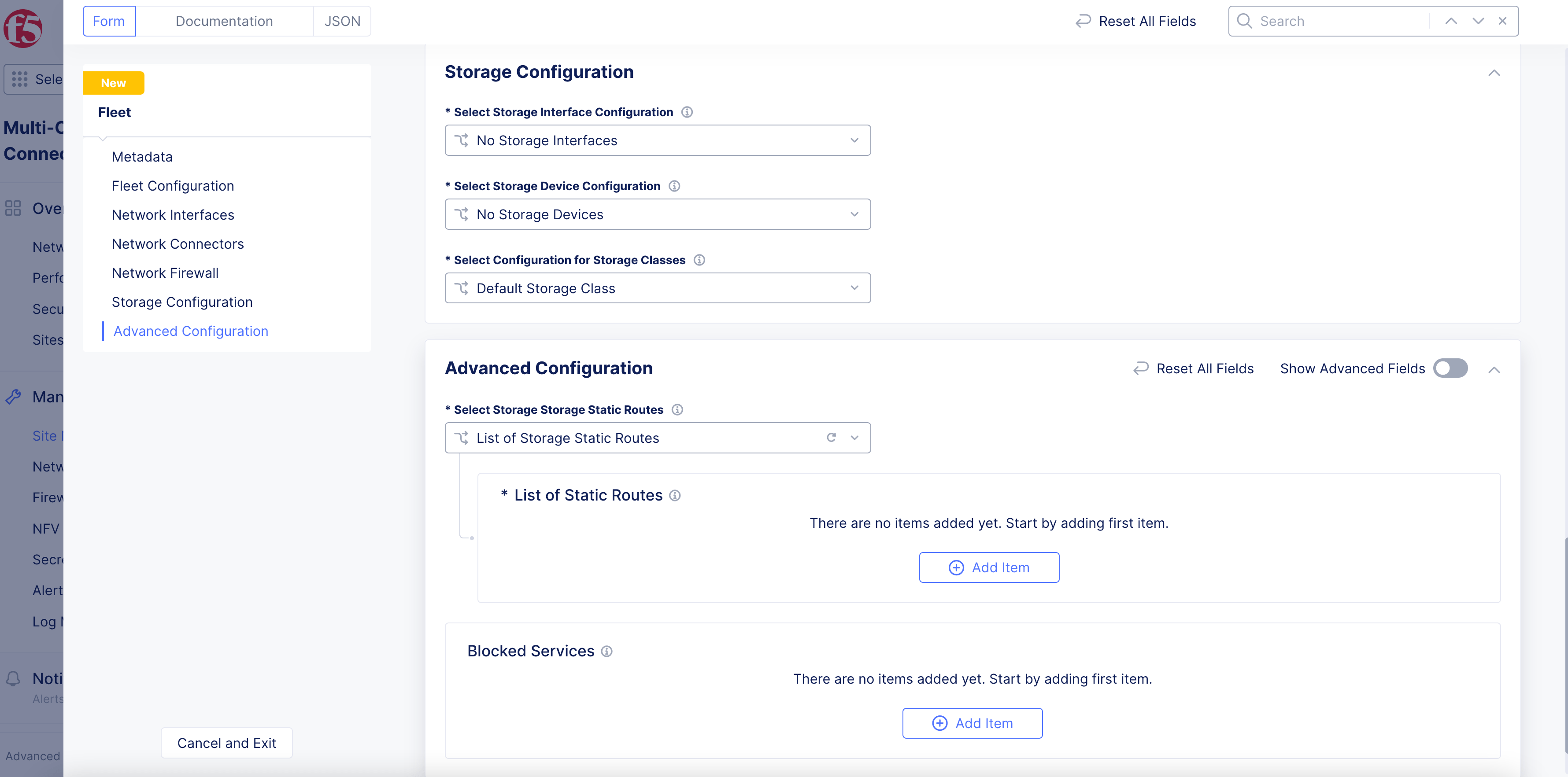
Figure: New Static Route
-
On the static route creation form, configure the following:
-
For the subnet configuration, click
Add Item. Select the IP version for the new route, any prefixes and prefix lengths, and then clickApply. -
In the
Nexthopsection, optionally perform configuration for route gateway, IP version, and network interface. -
Optionally, use
Add Labelto group routes together for network policies. -
Optionally, use the
Attributesmenu to select attributes for this new route. -
After you finish, click
Apply.
-
Step 8.2: Configure other options.
-
To configure more options, click
Show Advanced Fieldsand perform the following:-
To configure the cluster group, follow the instructions provided at Create App Stack Site.
-
To configure the GPU, follow the instructions provided at Deploy GPU Workload Using vK8s.
-
To configure log streaming, follow the instructions provided at Configure Streaming of Logs.
-
To configure USB device policy, follow the instructions provided at Manage USB Devices Using Fleet.
-
Step 9: Enable Fleet configuration download.
In the Advanced Configuration section, optionally enable the default Fleet configuration download option with Enable Default Fleet Config Download.
Note: You must enable the default Fleet configuration download if you configured the GPU and storage settings.
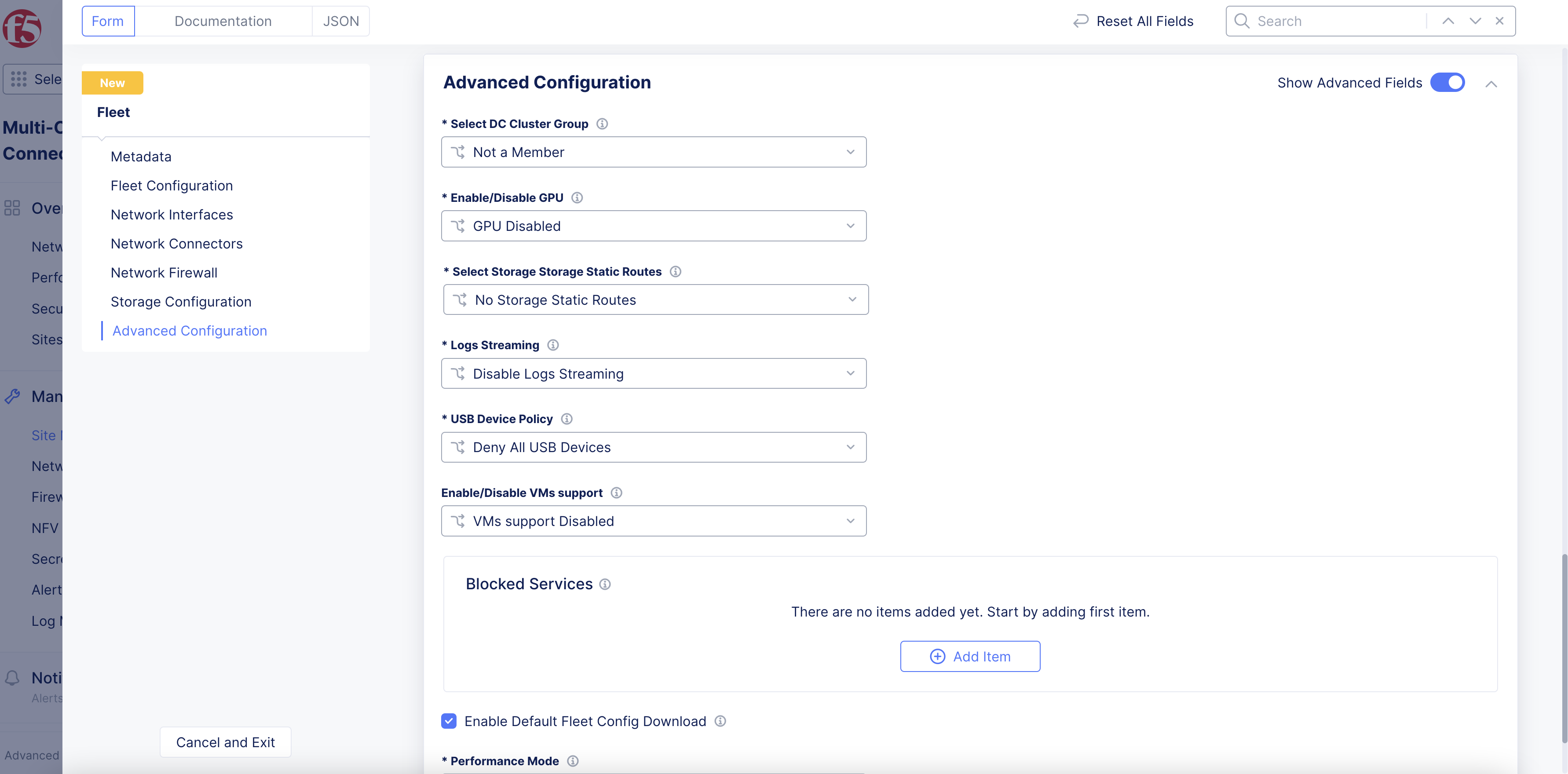
Figure: Enable Fleet Configuration Download
Step 10: Block services.
You can have your Fleet block services, like Web, DNS, and SSH.
In the Blocked Services section, click Add Item to configure blocked services.
Step 11: Complete Fleet configuration.
After you finish, click Save and Exit.
Apply Fleet Label to Site
After your Fleet is configured, you will need to apply its label on your sites so that the sites are configured with the Fleet settings.
Step 1: Navigate to your site.
-
To edit a non-cloud site, click
Overview, and then clickSites. -
Find your site, click
...and then clickManage Configuration. -
Click
Edit Configuration.
Step 2: Apply the Fleet label.
-
In the
Labelsbox form, clickAdd Label. Start by typing “fleet” and you will see the key-value pairves.io/fleet. Select this key-value pair. -
Type the name of your Fleet label, and then select it.
Step 3: Save the configuration.
Click Save and Exit.
Your site is now part of the Fleet that you previously configured.
Fleets Tab
The Fleets tab shows a list of your fleets along with some metrics for the sites included in that fleet.
Fleets Details
- Each fleet in the list has its own section showing the number of sites in the fleet, some health statistics, and a chart showing the memory and CPU usage for each site in the fleet (Each dot represents a site).
- Hover over a site the graph to see site name, node name, and actual memory and CPU usage values.
- Click on the fleet name to see a site map of the sites in the fleet (the default) or a list of sites in the fleet (in the
Site Listtab).
Site in a Fleet
- From the
Overview>Infrastructure>Sitespage, go to theFleetstab. - Find the fleet containing your site and click the fleet name.
- Use either the
Site MaporSite Listtabs to find and click on your site, as described above.
Upgrade Sites Using Fleet
A fleet is used to perform upgrades to the site software and operating system software. You can also use fleet to add or delete devices such as network interfaces or storage devices to the fleet of sites. This document covers information on how to perform software upgrades using the fleet.
Fleet upgrades are not supported for clouds sites, such as AWS VPC, AWS TGW, Azure VNet, GCP Credentials, or F5® Distributed Cloud App Stack sites.
Note: The outcome of attempts to perform upgrades using the Fleet are dependent on the
Site Software Version Overridesetting of the site that is part of the fleet. The following list describes the behavior:
If the set value of override is
Site Version Overrides, then the version set in site always takes precedence.If the set value of override is
New Version Overrides, then the newer version among site and fleet takes precedence.If the set value of override is
Fleet Version Overrides, then the version set in fleet always takes precedence.
Upgrade a Fleet
The upgrade feature enables you to upgrade the software and operating system software versions for your Fleet of sites.
Step 1: Navigate to your fleet in Console.
- Log into Console, and then click
Multi-Cloud Network Connect.
Figure: Console Homepage
- Click
Manage>Site Management>Fleets.
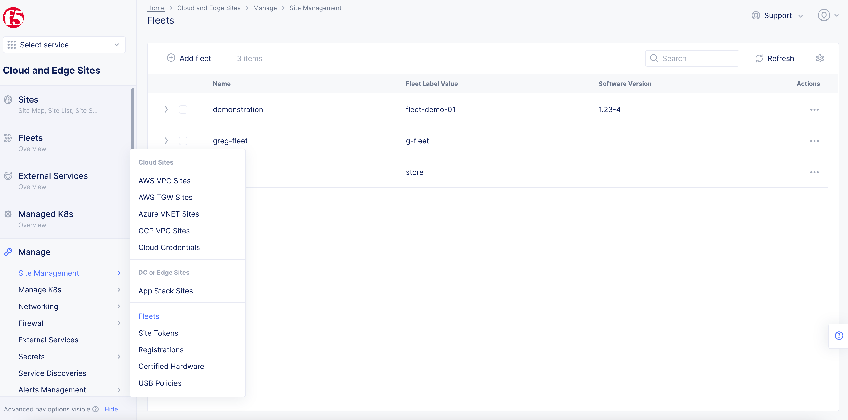
Figure: Navigate to Fleets
- Click
...and then clickManage Configurationon the fleet object to which your sites are associated with.
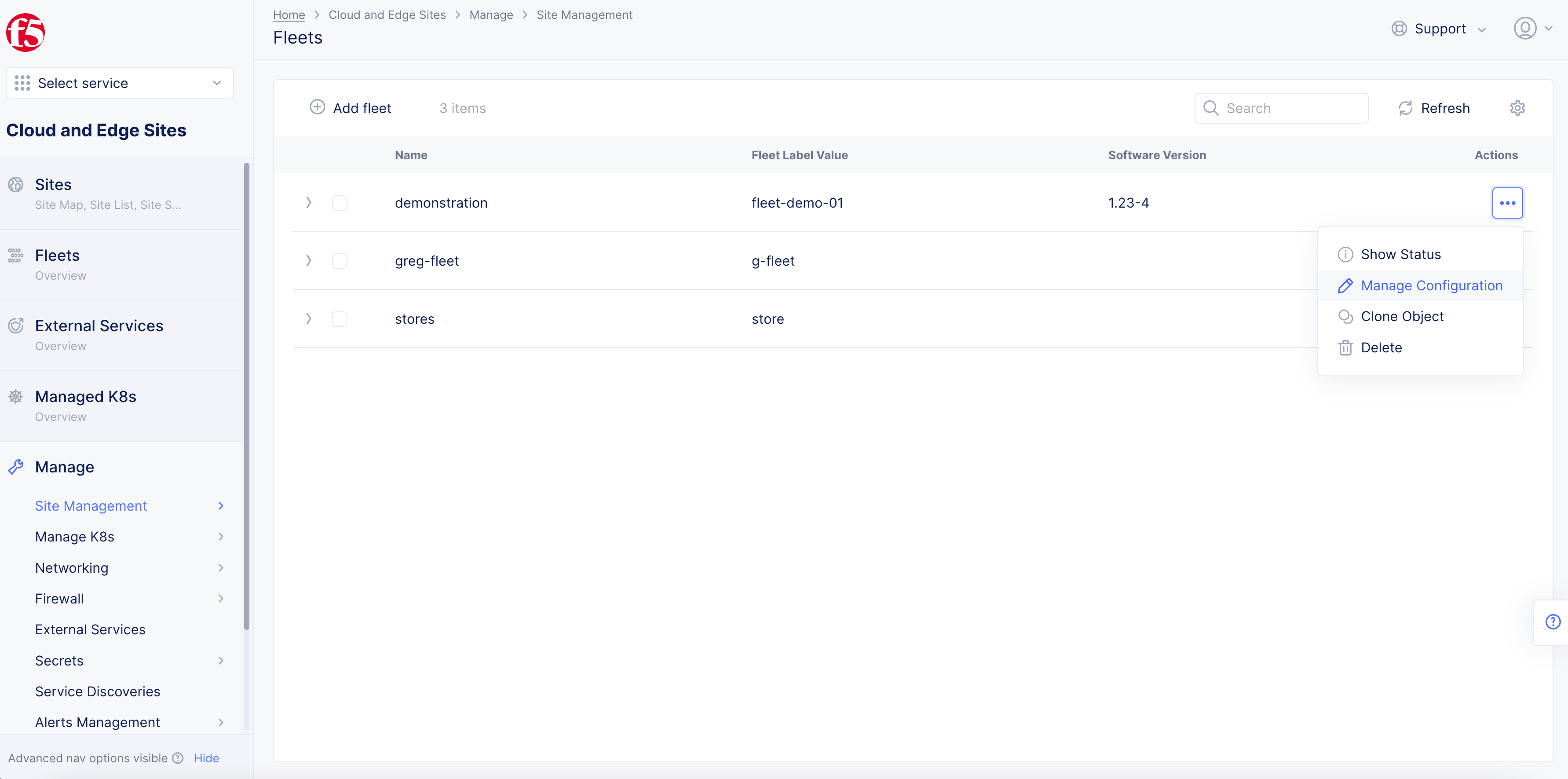
Figure: Edit Fleet
- In the form that appears, click
Edit Configurationfrom the top right corner.
Step 2: Set the site software version and operating system version.
- In the
Fleet Configurationsection, enter the software version or operating system version to which you want the sites to be upgraded in theSoftware VersionandOperating System Versionfields, respectively.
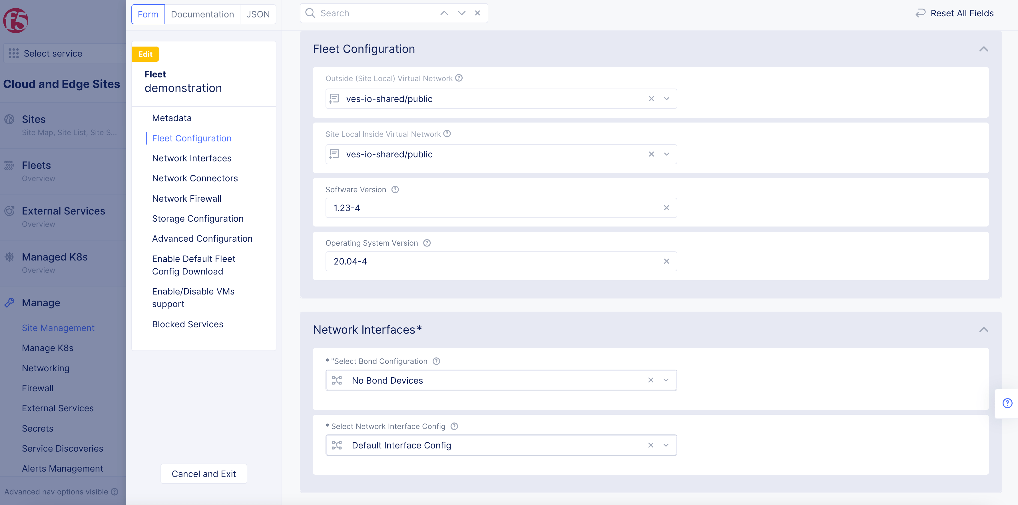
Figure: Fleet Configuration Versions
Note: Navigate to
Sites>Site List. Click...and then clickEditfor your site and ensure that theFleet Version Overridesoption is set for theSite Software Version Overridefield.
-
Click
Save and Exitto save the updated fleet configuration. -
Navigate to
Sites>Site Listto display the available upgrades to your sites under theSW version (Current / Status)andOS version (Current / Status)fields.
Step 3: Verify your fleet was upgraded.
-
Navigate to
Fleets>Overview. -
Click on the entry for the fleet for which you set the software and operating system versions.
-
Click the
Site Listtab to display the list of sites that are part of your fleet. -
In the
SW version (Current / Status)andOS version (Current / Status)fields, confirm that the values match the versions you applied to your fleet configuration. The values with messagesScheduledorIn progressindicate that the upgrade is planned or triggered. The messageSuccessfulindicates that the upgrade was completed successfully.
Configure Multi-Node Site Network Using Fleet
This guide provides instructions on how to configure the networking configuration for each node in a multi-node site using F5® Distributed Cloud Services Fleet. All the multi-node sites belonging to the Fleet will be configured equally, and you can further enhance the security by adding a network firewall to the Fleet, to ensure consistent security policy across all the sites in the Fleet. These instructions cover the following:
-
IP address management of outgoing interfaces (toward the Internet).
-
IP address management of interfaces toward inside networks.
-
Segmentation of subnets using virtual local area networks (VLANs).
Configuration Diagram
The following diagram shows an example topology for the use case presented in this guide:
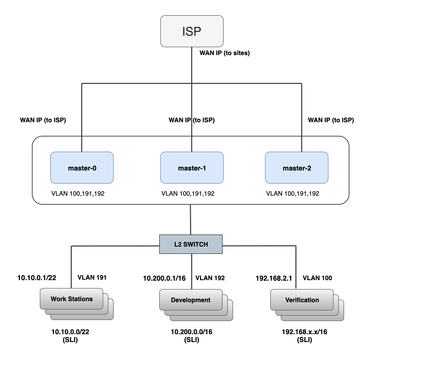
Figure: Sample Network Topology
The example in this topology sets up a multi-node site as a network gateway for inside networks. The gateway has three control nodes and a Layer 2 switch with three VLANs for segmentation of employee workstations, development servers, and test servers. To set up this topology, you need to configure the following in the Fleet object:
-
Two virtual networks: one outside network and one inside network. This example creates inside and outside networks as part of Fleet.
-
Set up the following network interfaces:
- Dedicated Interfaces on the Site Local Outside (WAN).
Note: The IP addressing must be static or a fixed DHCP lease from an upstream DHCP server. Changing of SLO IP addresses in a multi-cluster setup is currently not supported.
-
Ethernet Interface for the Site Local Inside Network. We will configure Static Node Address, a DHCP Server, and DHCP Fixed Leases for internal hosts such as printers.
-
Set up a site local breakout from the Inside to Outside network using the network connector with SNAT.
-
Finally, apply the Fleet with the above objects to your multi-node site to enable the network connectivity.
Configure Storage in Fleet
This guide provides instructions on how to set storage for your applications using the F5® Distributed Cloud Services fleet of sites. Storage configuration set using fleet gets applied to all the sites that are part of the fleet and will be accessible to the workloads on those sites. For more information on fleets, see Fleet.
Using the instructions provided in the document, you can define the following storage configuration using fleet:
-
Storage devices: Configuration for a specific hardware appliance.
-
Storage classes: Class to which the appliance belongs to and this is dependent on the appliance provider. For example, a class can be a fast pool or slow pool of devices.
-
Storage interfaces: Interfaces for storage devices.
Procedure
Use the following steps to configure storage for your applications.
Note: By default, a Distributed Cloud site deployed in AWS will support Elastic Block Store (EBC), GCP supports Google Cloud Storage, and Azure supports Azure Disk Storage.
Step 1: Navigate to the Fleets page.
-
Select the
Multi-Cloud Network Connectservice. -
Navigate to
Manage>Site Management>Fleets.
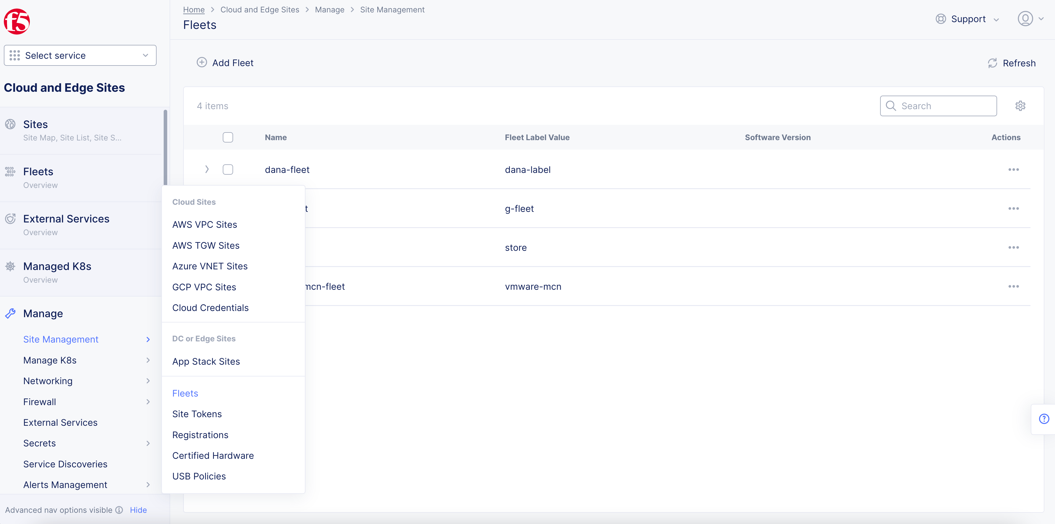
Figure: Fleet list
Step 2: Edit fleet set interfaces for storage.
-
Select
...>Managefor the fleet object you want to define storage configuration. -
Click
Edit Configurationin the upper right corner. -
Navigate to the
Storage Configurationsection. -
From the
Select Storage Interface Configurationmenu, selectList of Storage Interface. -
Select an interface from the displayed list or click
Add Item. You can add multiple interfaces using theAdd itemoption.
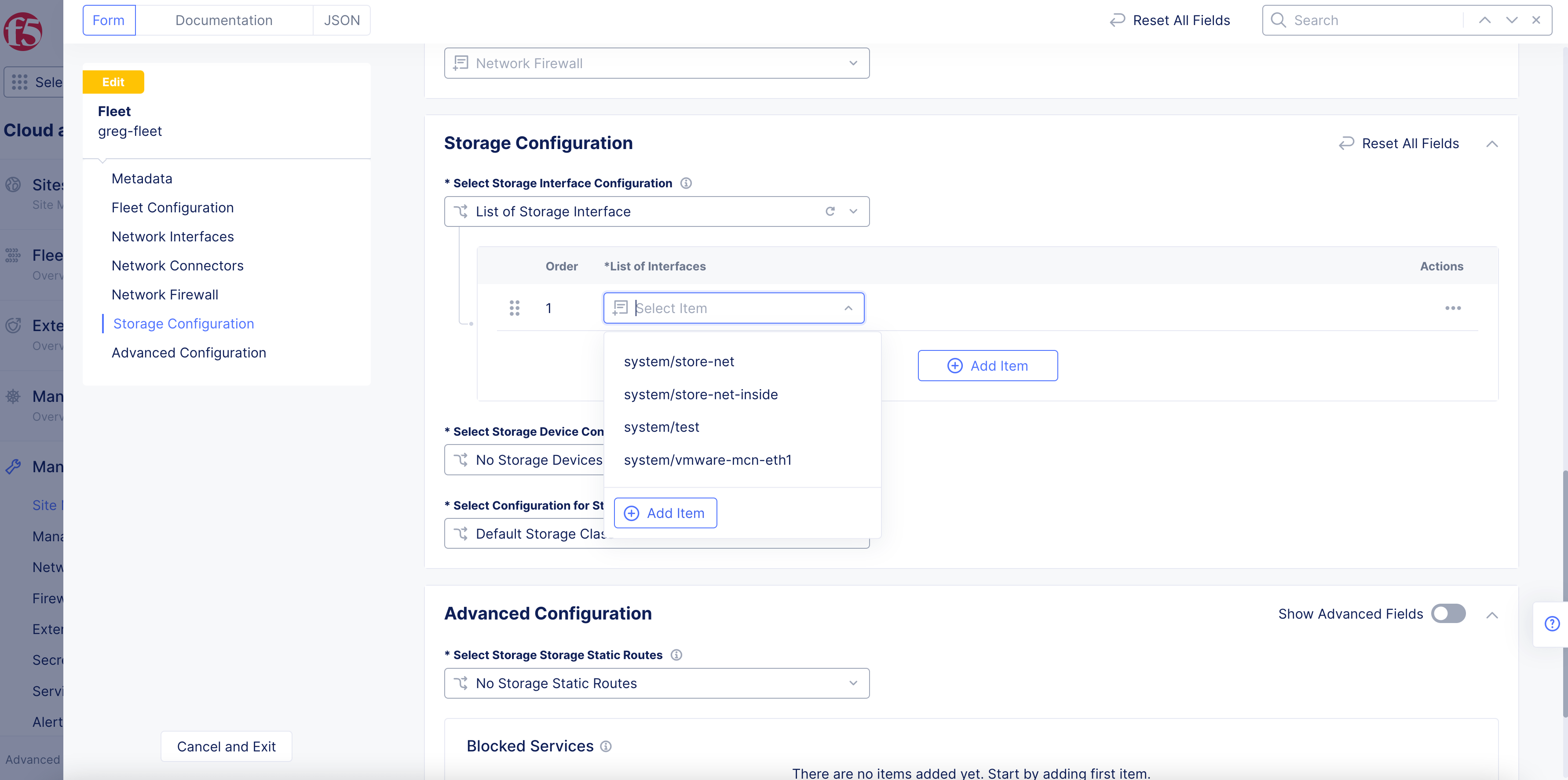
Figure: Interfaces for Storage Devices
Step 3: Configure storage devices.
- From the
Select Storage Device Configurationmenu, selectList of Storage Devices
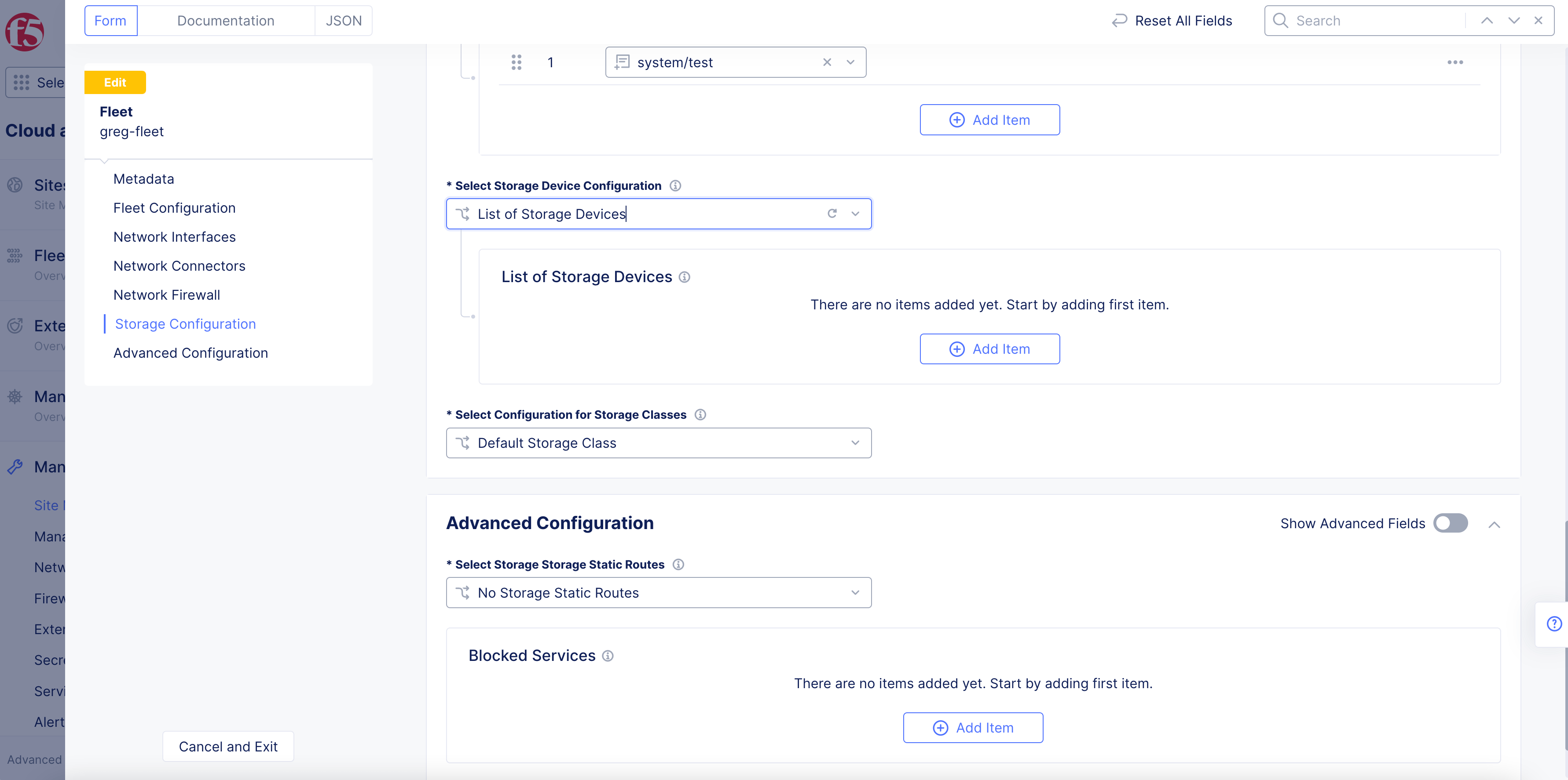
Figure: Storage Devices Option
-
Under the
List of Storage Devicesfield, clickAdd Item. -
Enter a name in the
Storage Devicefield. Ensure that this name corresponds to the class in which the storage device falls. The classes are used by vK8s for storage related actions.
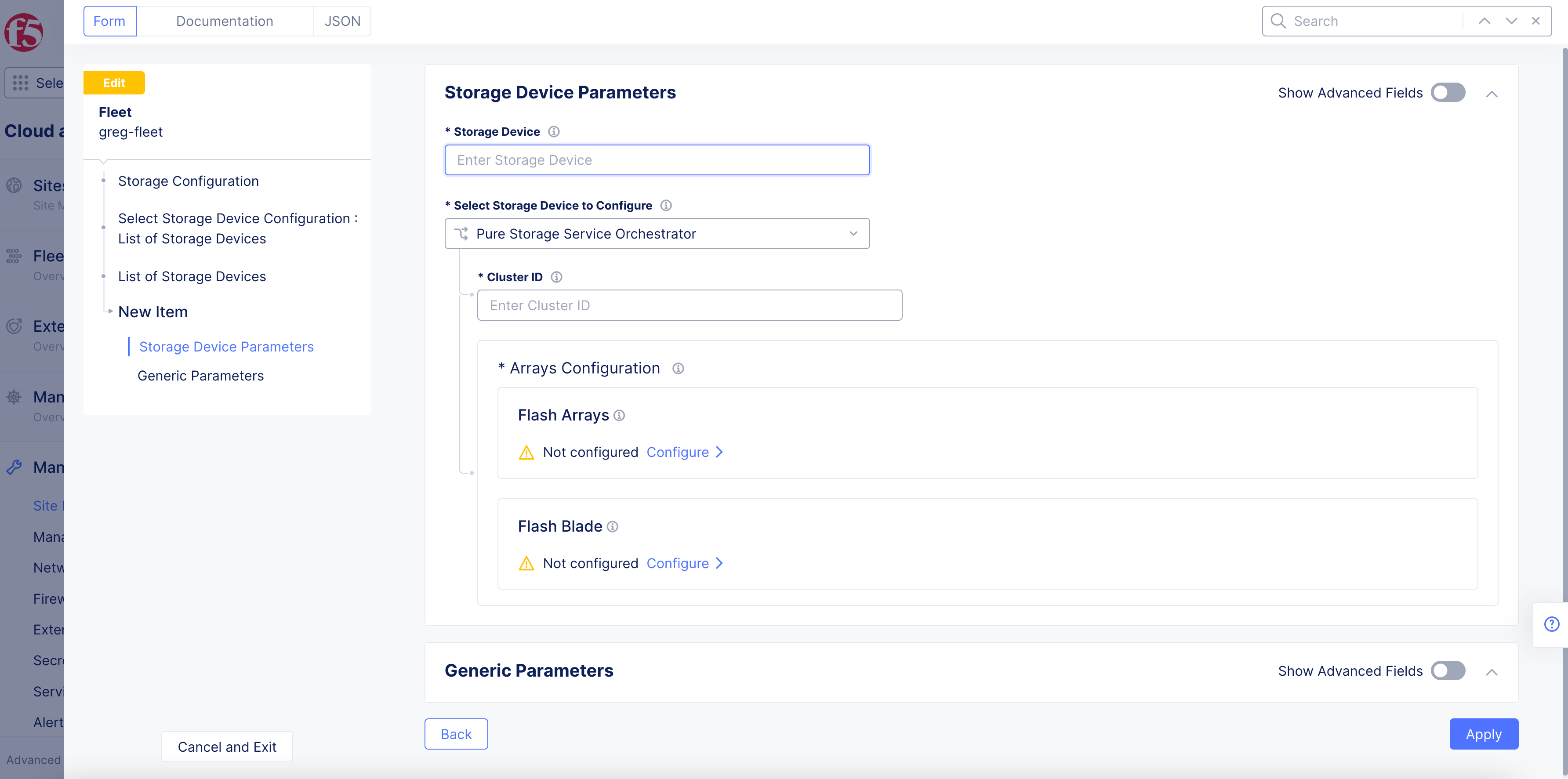
Figure: Storage Devices Parameters
- From the
Select Storage Device to Configuremenu, select an option and perform one of the following based on that option:
NetApp Trident
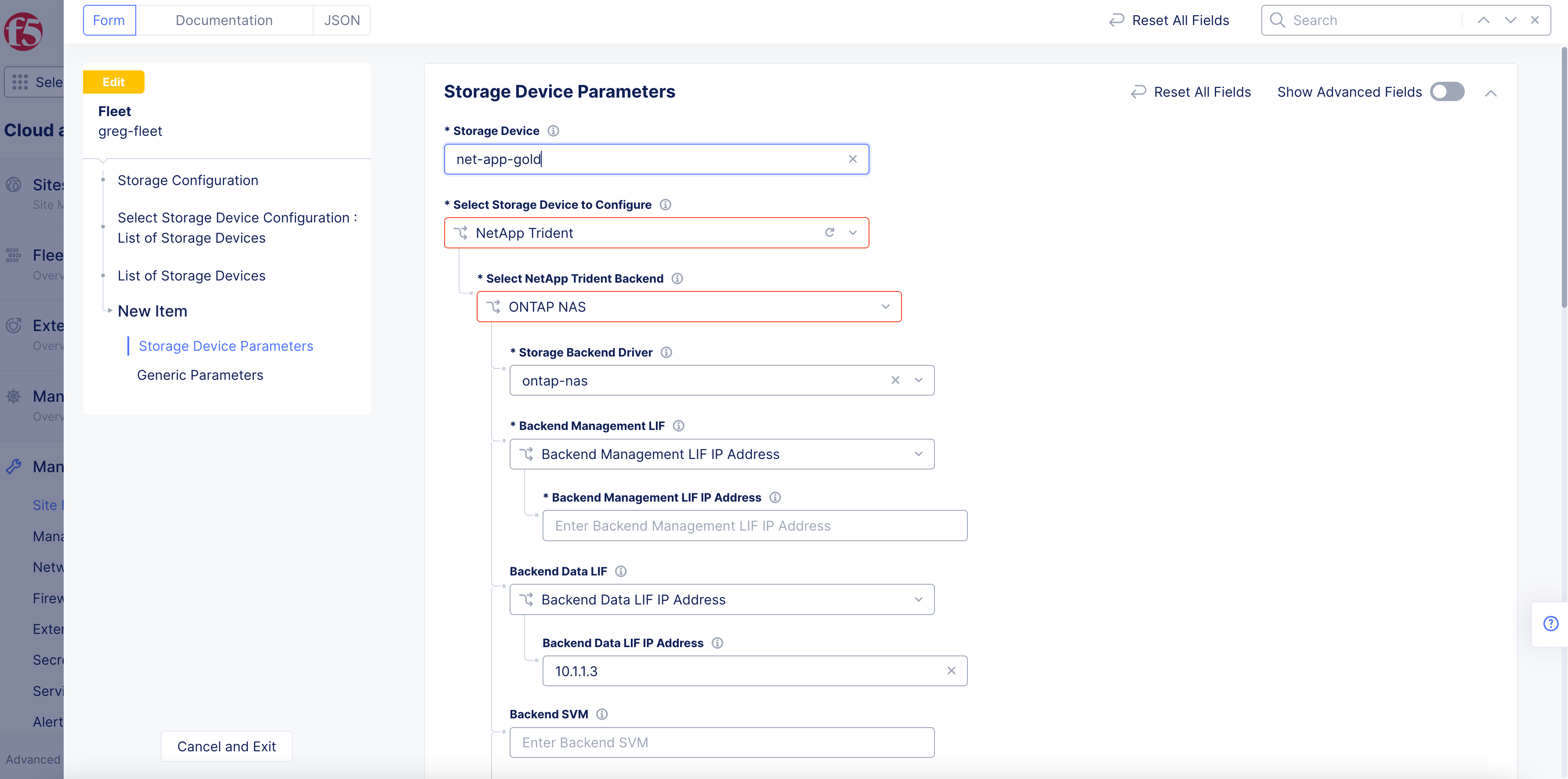
Figure: NetApp Device Backend LIFs
-
From the
Select NetApp Trident Backendmenu, select an option. TheONTAP NASis selected by default. -
Select an option from the
Backend Management LIFmenu. TheBackend Management LIF IP Addressis selected by default. Enter an IP address for the backend management logical interface in theBackend Management LIF IP Addressfield. In case you select the name option, enter the backend management interface name. -
Select an option from the
Backend Data LIFmenu. TheBackend Data LIF IP Addressis selected by default. Enter an IP address for the backend data interface in theBackend Data LIF IP Addressfield. In case you select the name option, enter the backend data interface name. -
Enter a username in the
Usernamefield. ClickConfigurefor thePasswordfield. Enter your password in theSecretpage and clickBlindfold. Wait for the Blindfold to complete encrypting your password and clickApply. -
Enter a certificate in the
Client Certificatefield. ClickConfigurefor theClient Certificatefield. Enter your text for your secret in theSecretpage and clickBlindfold. Wait for the Blindfold to complete encrypting your password and clickApply. -
Enter a certificate in the
Trusted CA Certificatefield. ClickConfigurefor theTrusted CA Certificatefield. Enter your text for your secret in theSecretpage and clickBlindfold. Wait for the Blindfold to complete encrypting your password and clickApply.
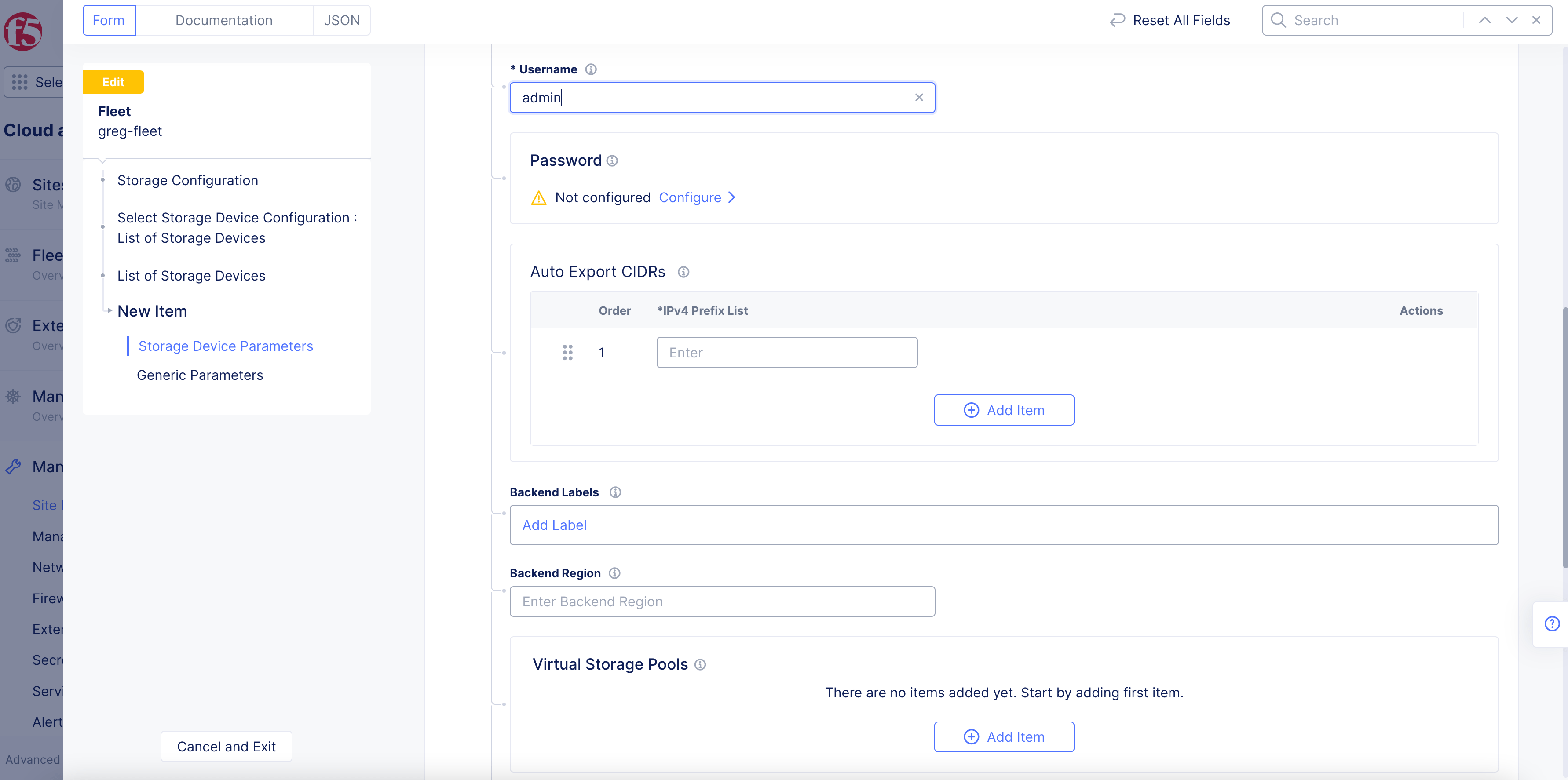
Figure: NetApp Device Password
- Enter CIDR for your K8s nodes in the
Auto Export CIDRsfield in case auto export policy is enabled for your storage device.
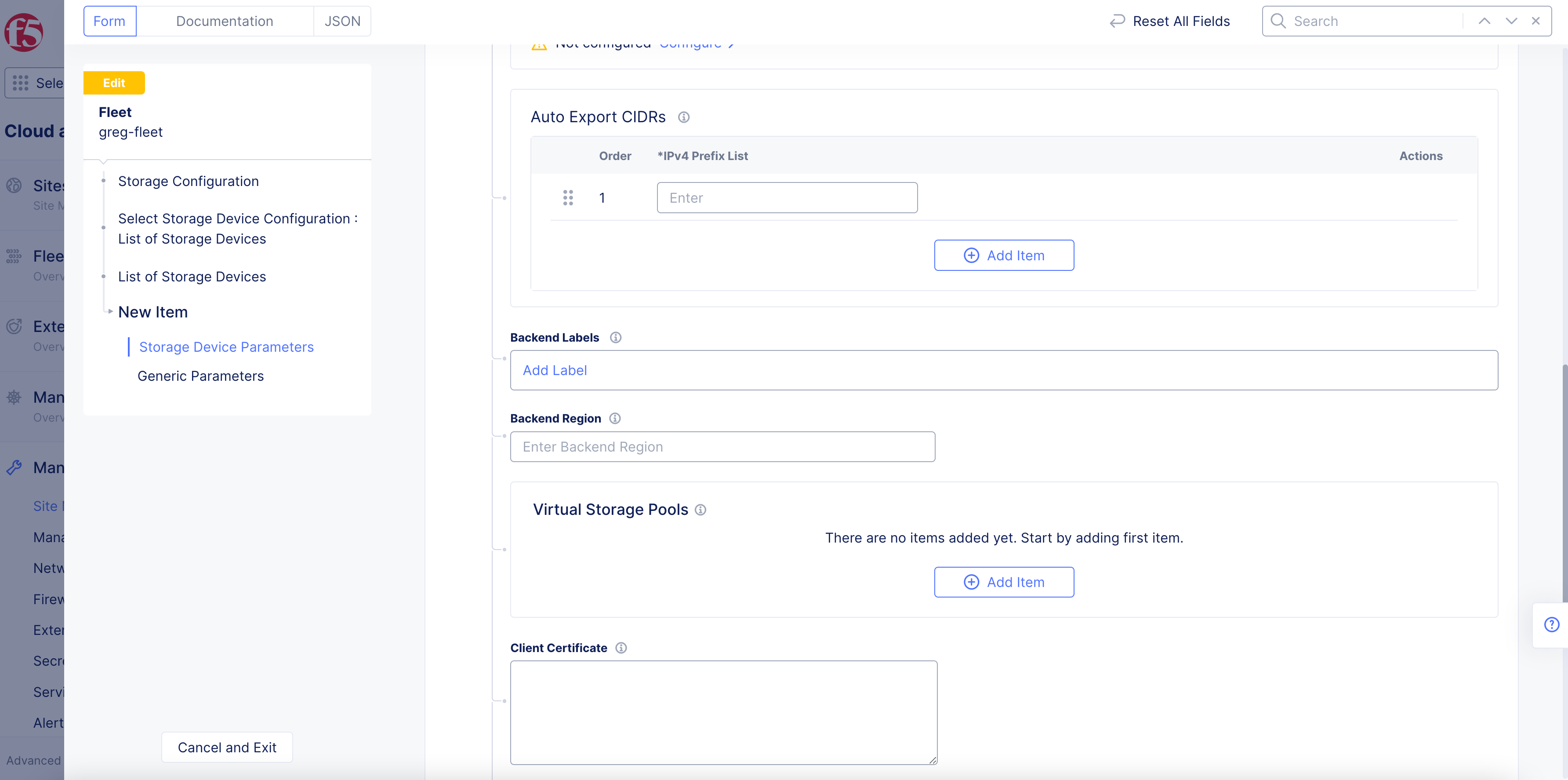
Figure: NetApp Device AutoExport CIDRs
-
If you are configuring virtual storage, then in the
Virtual Storage Poolssection, enter a label and region for the storage, and clickAdd Itemone or more times to add pool labels and pool zones. -
Click
Apply.
Pure Storage Service Orchestrator
- Enter a cluster identifier in the
Cluster IDfield. This is used to identify the volumes used by the datastore. Alphanumeric characters and underscores are allowed.
Note: Unique cluster ID is required for multiple K8s cluster using the same storage device.
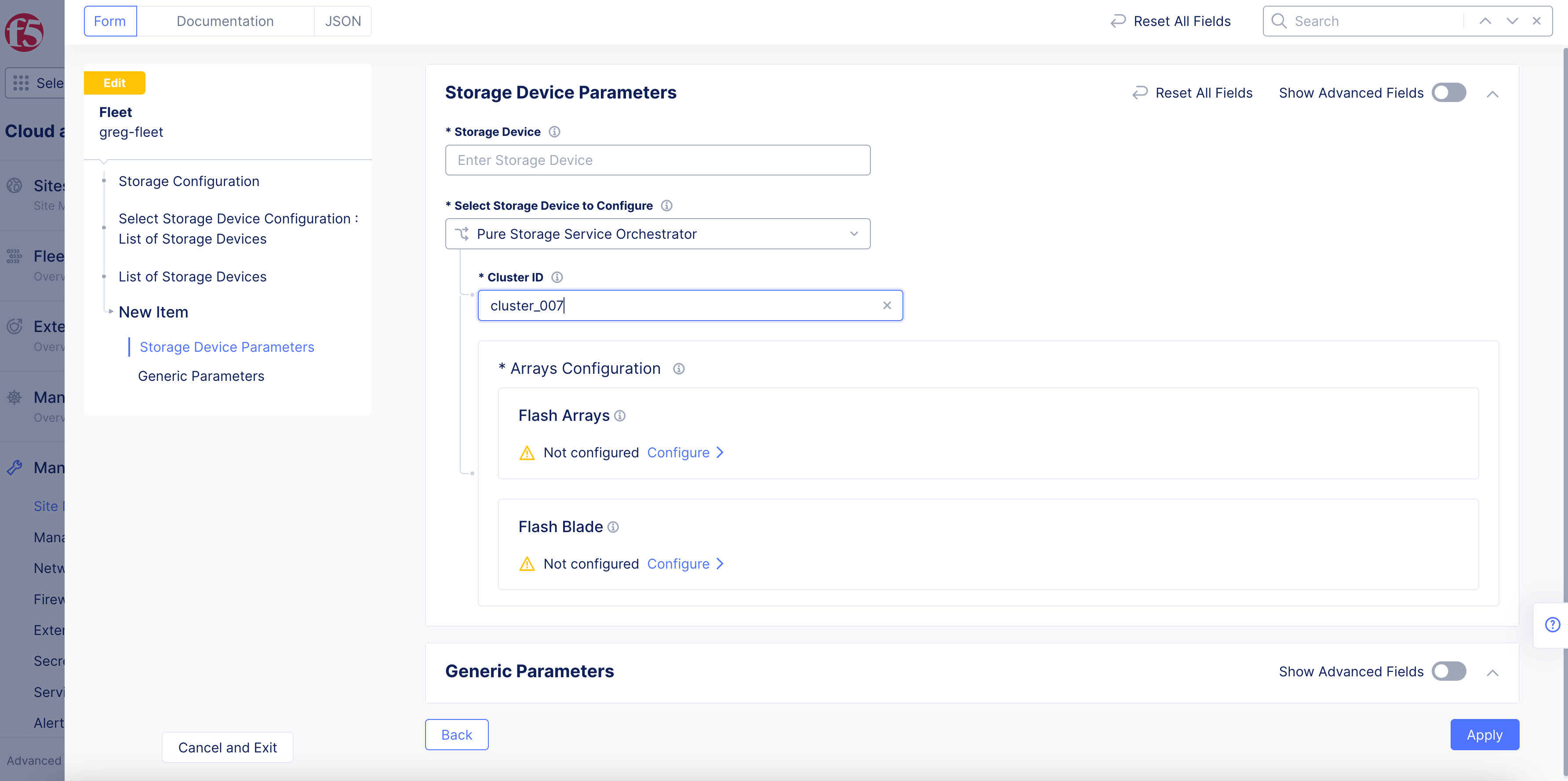
Figure: Pure Storage Orchestrator Device
-
Click
Configureunder theFlash Arraysfield. -
Click
Add Itemto add a flash array endpoint.
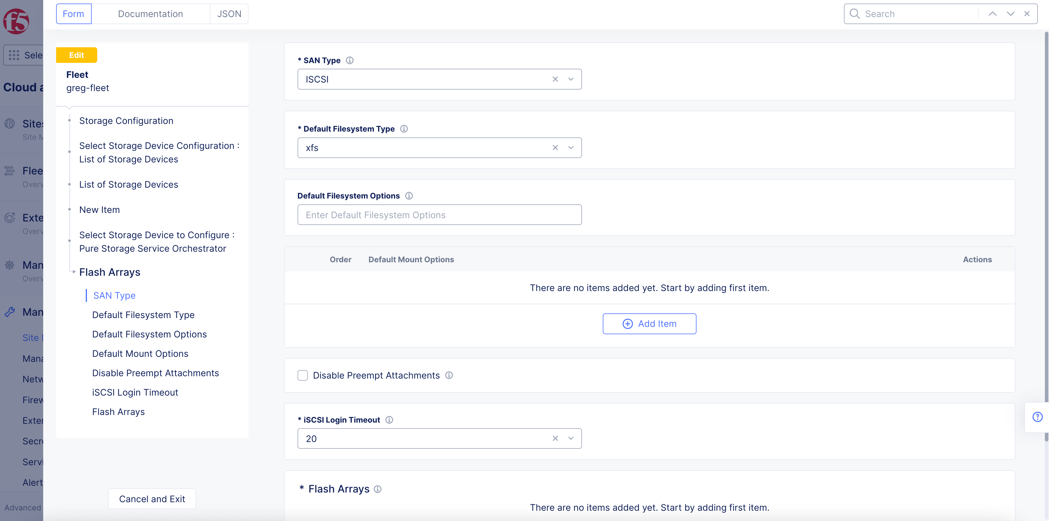
Figure: Pure Storage Flash Arrays
- Enter an IP address in the
Management Endpoint IP Addressfield.
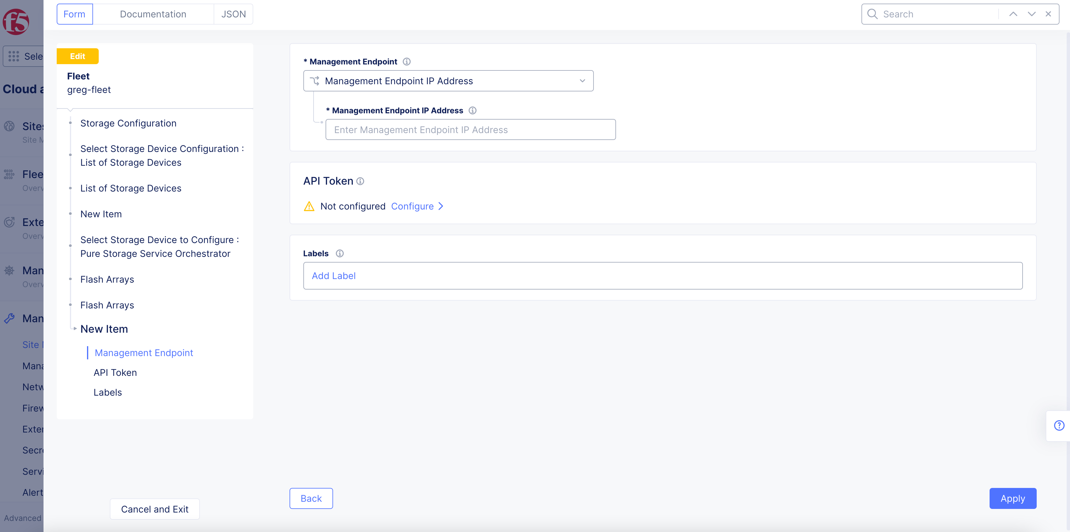
Figure: Pure Storage Flash Array endpoint
-
Click
Configureunder theAPI Tokenfield. Enter the token in the secret field and clickBlindfold. ClickApplyafter the Blindfold encryption is completed. -
Optionally, select labels for this endpoint.
-
Click
Apply. -
Click
Configureunder theFlash Bladefield. -
Click
Add Itemto add a flash blade endpoint.
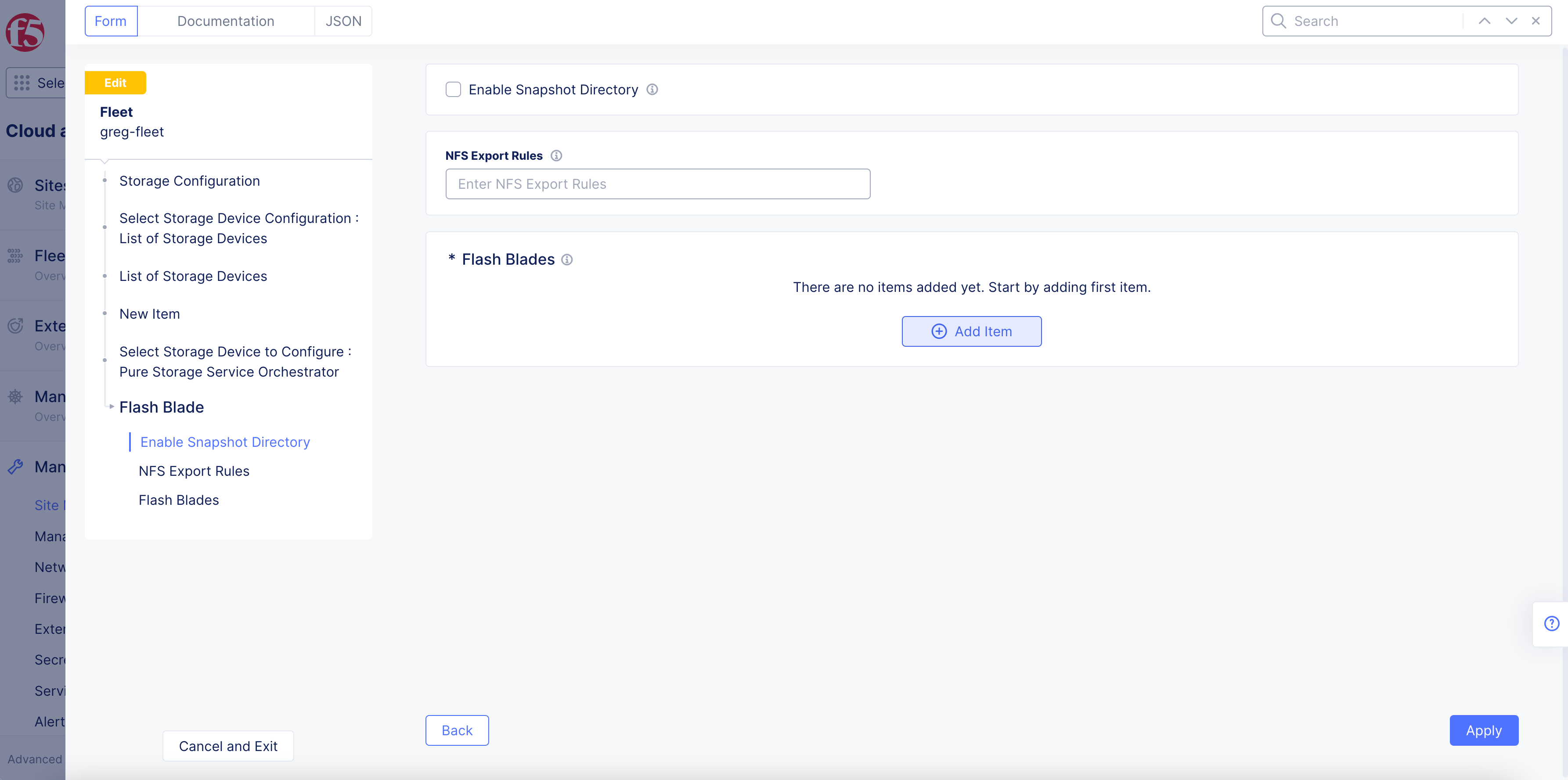
Figure: Pure Storage Flash Blade
- Enter the IP address in the
Management Endpoint IP Addressfield.
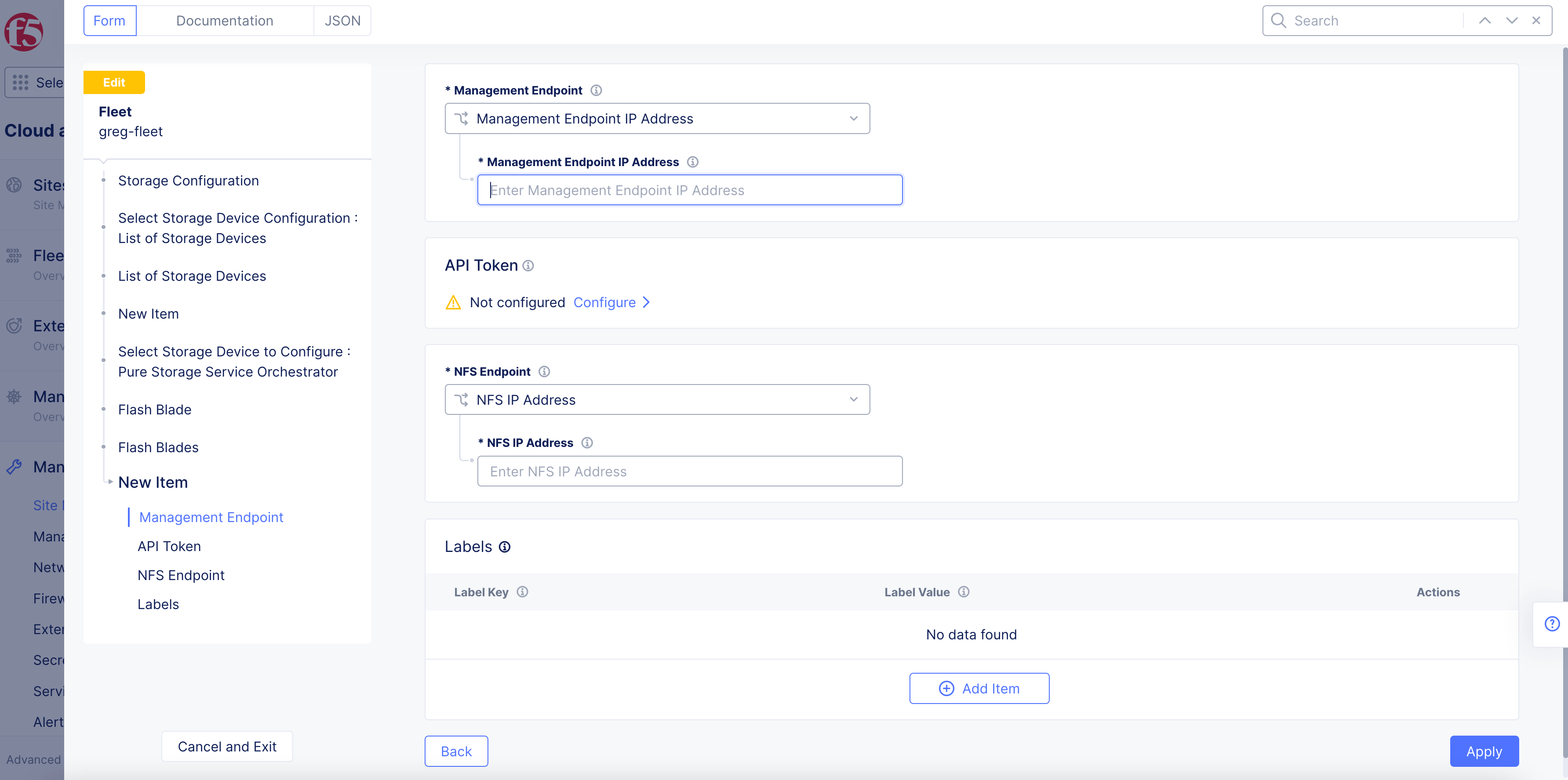
Figure: Pure Storage Flash Blade Endpoint
-
Click
Configureunder theAPI Tokenfield. Enter the token in the secret field and clickBlindfold. ClickApplyafter the Blindfold encryption is completed. -
Enter the IP address in the
NFS IP Addressfield. -
Optionally, add labels for this endpoint.
-
Click
Apply.
Note: You can change the management or NFS endpoints to specify management endpoint name or NFS DNS name.
- Click
Apply.
Custom Storage
The custom storage classes option is used for storage devices or external storages which are deployed outside F5 Distributed Cloud Services. For example, the option allows you to configure custom storage classes for AWS, GCP, etc.
-
Select
Custom Storagefor theSelect Storage Device to Configurefield. -
Click
Add Item.
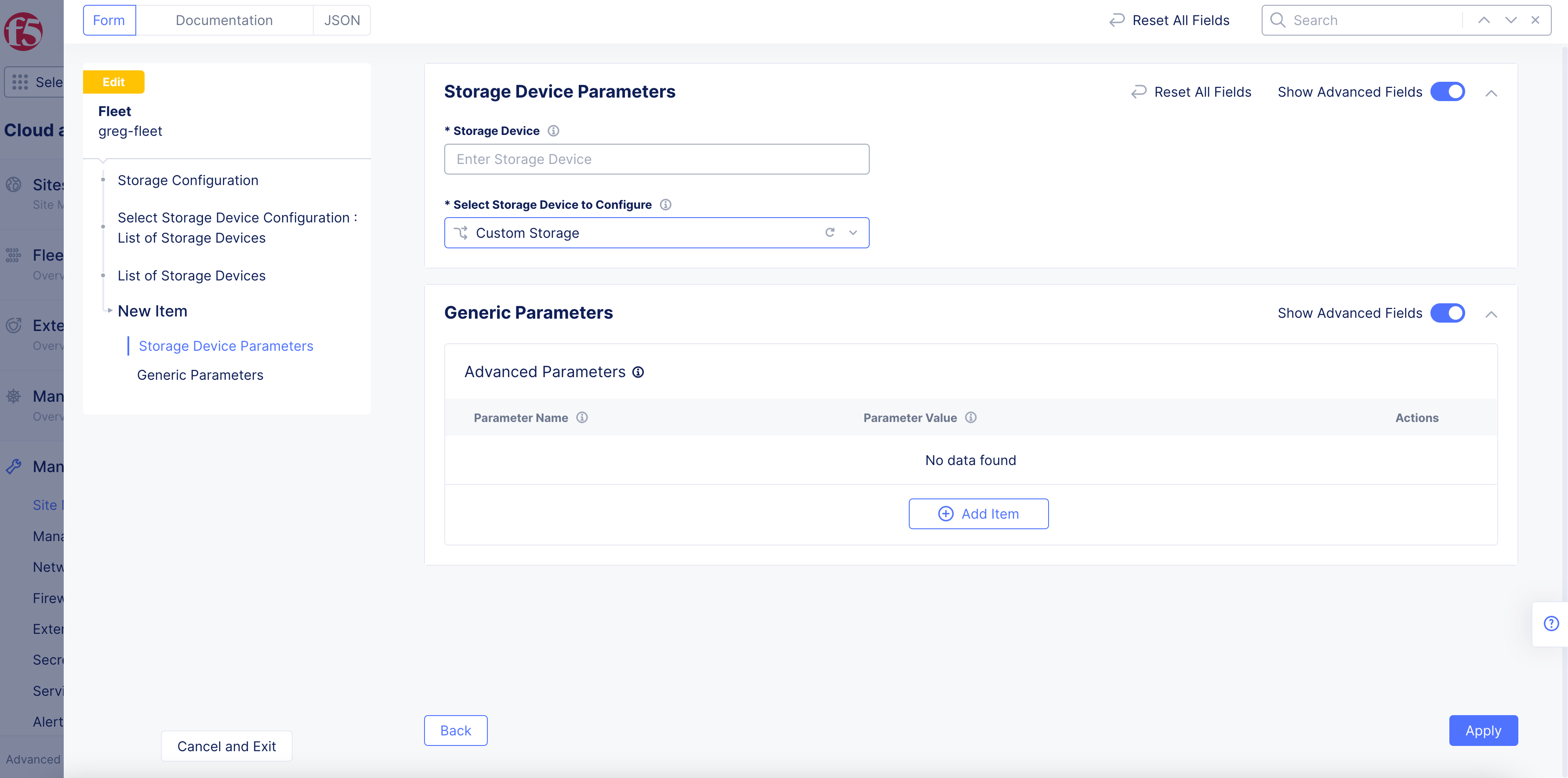
Figure: Custom Storage Device
-
Optionally, in the
Parameter NameandParameter Valuefields, enter the required information. -
Click
Apply.
HPE Storage
-
Select
HPE Storagefor theSelect Storage Device to Configurefield. -
In the
Storage Namefield, enter a name. -
In the
Storage Server IP addressfield, enter an IP address. -
In the
Storage server Portfield, enter a port number. -
In the
Usernamefield, enter the username used to connect to the HPE storage device. -
To configure the password, click
Configure. Then perform the following:-
For the
Blindfolded Secretoption, complete the configuration by entering the secret text to blindfold. -
For the
Clear Secretoption, enter the secret text in plaintext format or Base64. -
Click
Apply. -
Click
Applyagain to complete configuration.
-
Note: You can add multiple devices using the
Add itemoption.
Step 4: Configure storage classes.
You can use default storage classes supported in K8s or you can customize the classes. If you are using default classes, ensure that the storage device names correspond to the K8s classes.
NetApp Trident
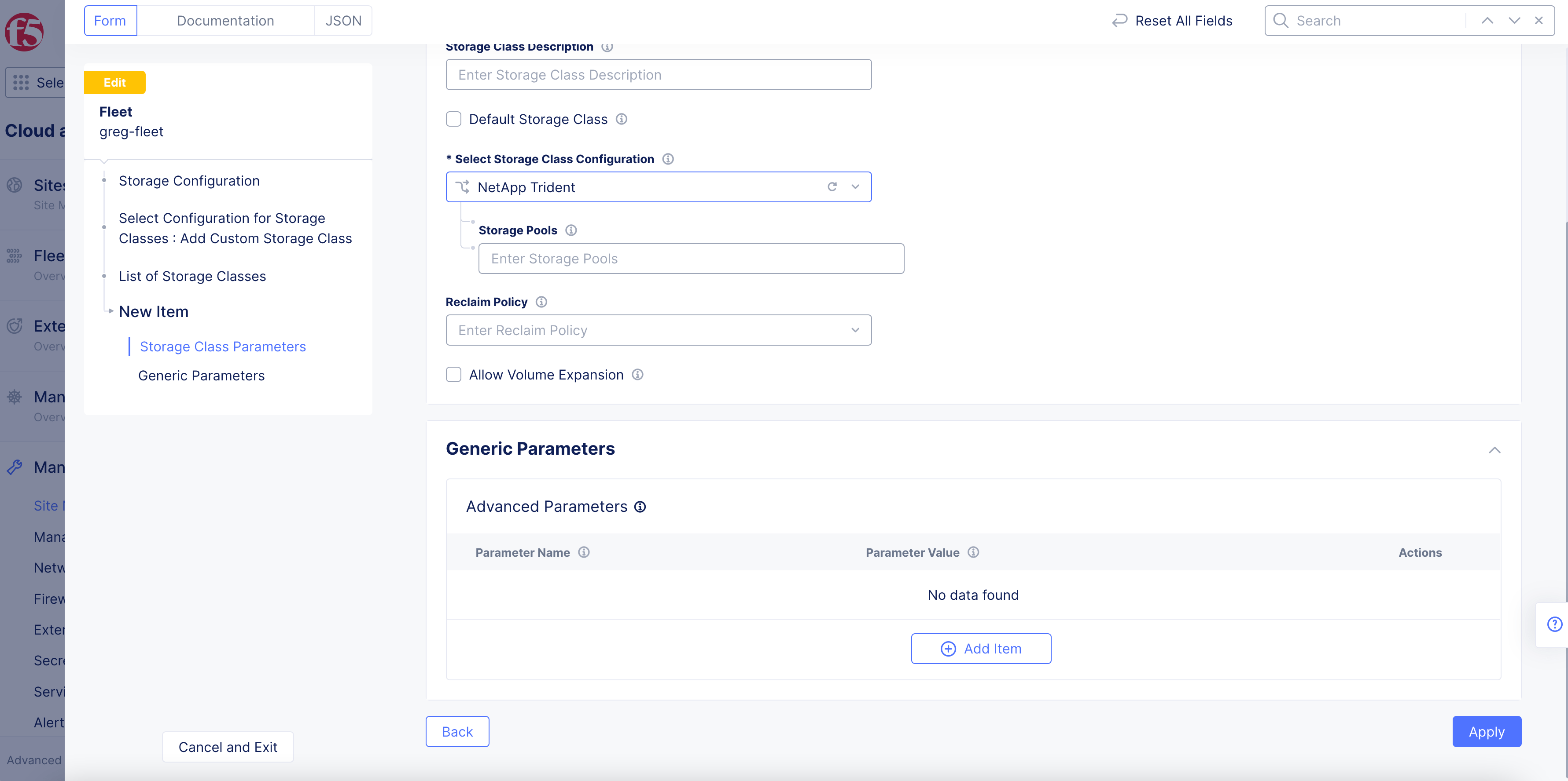
Figure: NetApp Class
- Click
Add Item.
Pure Storage Service Orchestrator
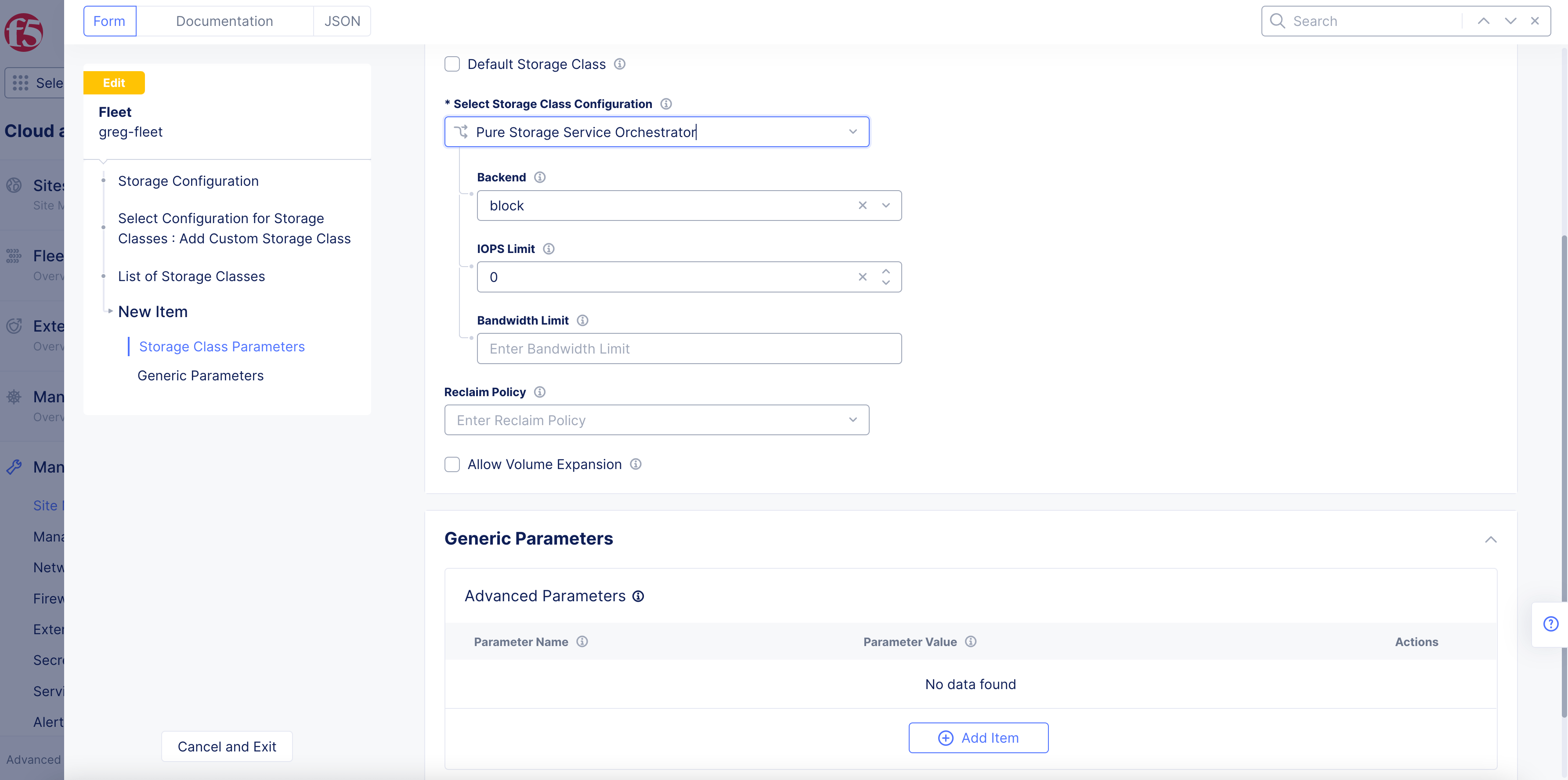
Figure: Pure Storage Orchestrator Class
-
Select an option from the
Backendmenu. Theblockoption is selected by default. -
Optionally, enter IOPS and bandwidth limits in their respective fields.
-
Click
Add Item.
Custom Storage Class
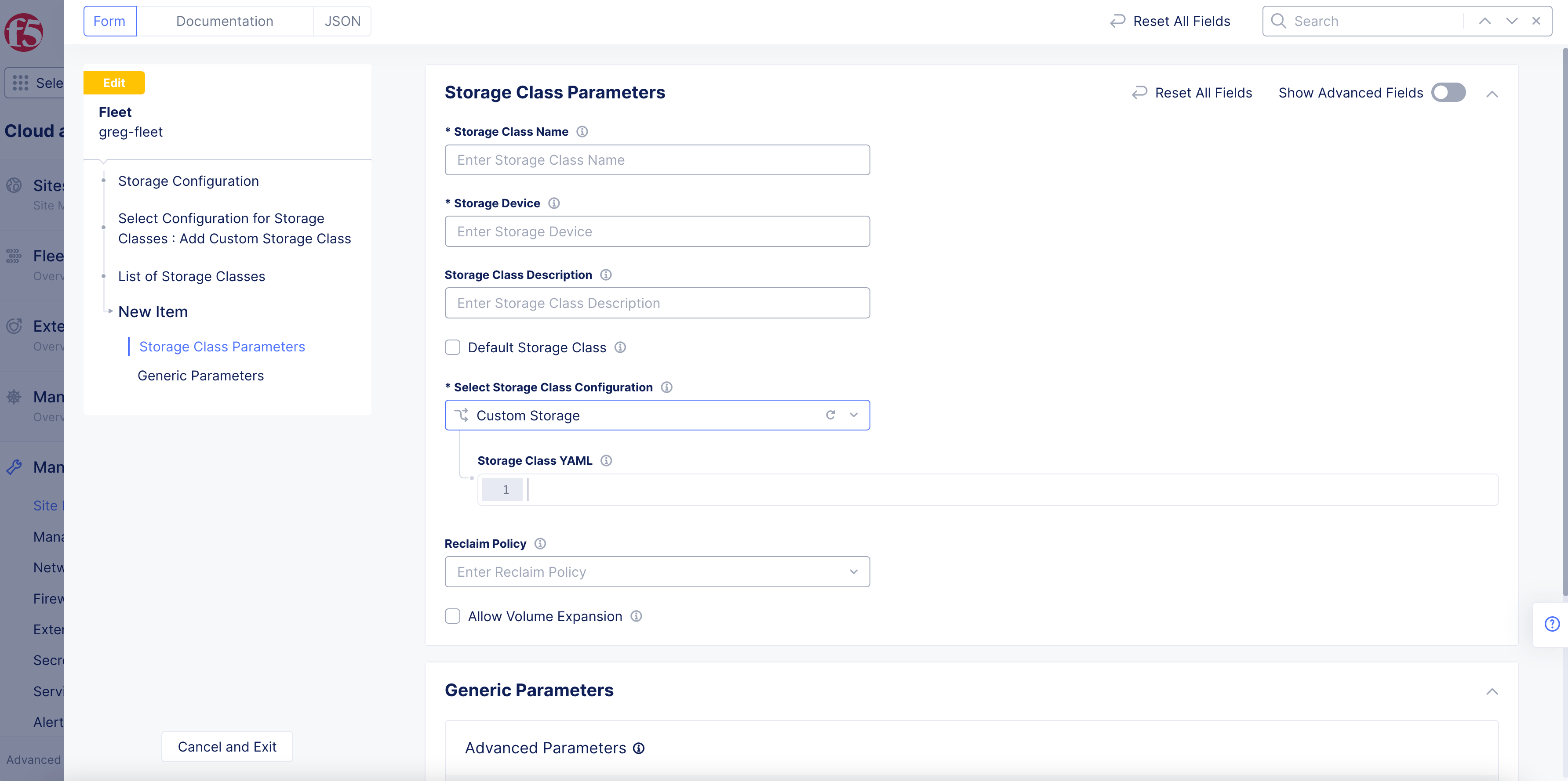
Figure: Storage class parameters
-
Select
Add Custom Storage Classfor theSelect Configuration for Storage Classesfield. -
Click
Add Itemunder theList of Storage Classesfield. This opens theStorage Class Parameterspage. -
Enter a name for the
Storage Class Namefield. This name will appear in K8s. -
Enter a name in the
Storage Devicefield. This is the storage device that will be used by this class, as entered in Step 3. -
Optionally, enter a storage class description.
-
Optionally, check the
Default Storage Classbox to make this storage class the default for the K8s cluster. -
Select
Custom Storagefor theSelect Storage Class Configurationfield. -
Enter the storage class YAML. It must have the configuration of
apiVersion: storage.k8s.io/v1kind: StorageClass...-
Enter a
Reclaim Policy. -
Optionally, check the
Allow Volume Expansionbox. -
Optionally, enter generic/advanced parameters.
-
Click
Add Item.
HPE Storage
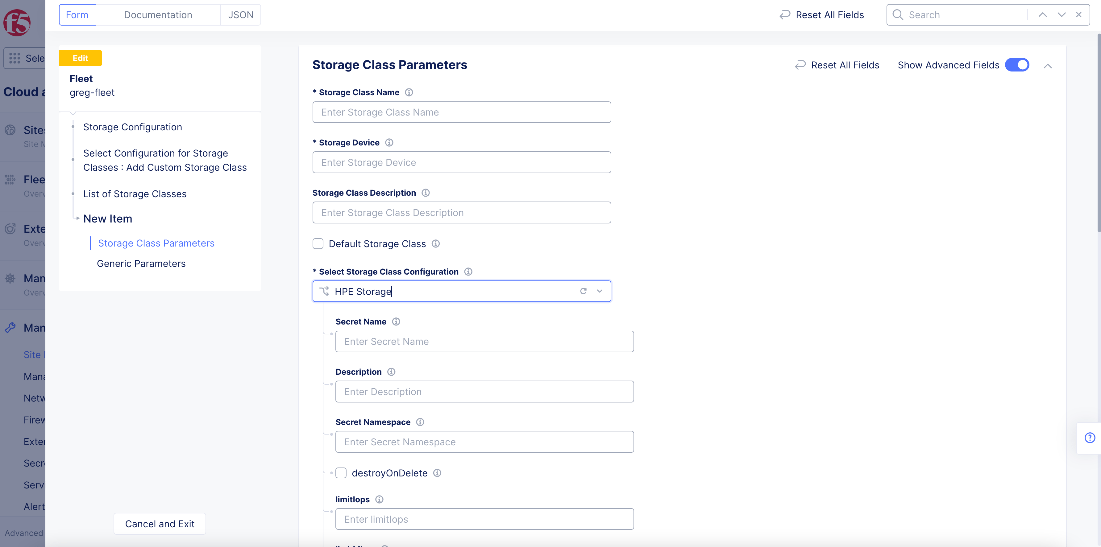
Figure: Storage class parameters
Complete the required parameters.
Note: You can add multiple classes using the
Add itemoption.
Step 5: Complete applying storage configuration to fleet.
Click Save and Exit to apply the storage configuration fleet.
Manage USB Devices Using Fleet
This guide provides instructions on how to manage USB devices for your sites using fleet configuration in the F5® Distributed Cloud Console (Console). See Fleet for conceptual details of the fleet.
You can enable or disable access to USB devices for your sites via the fleet configuration. By default, all USB devices are denied in the fleet, and you can allow all or attach USB device policies to manage specific devices. You can also create a USB device policy from within the fleet configuration.
Using the instructions in this guide, you can update fleet configuration to enable or disable access to all or specific USB devices for your sites that are part of the fleet.
Apply USB Device Policy Using Fleet
Log into Console and perform the following:
Step 1: Navigate to fleets and start editing fleet configuration.
- In Console, click
Multi-Cloud Network Connect.
Figure: Console Homepage
- Click
Manage>Site Management>Fleets.
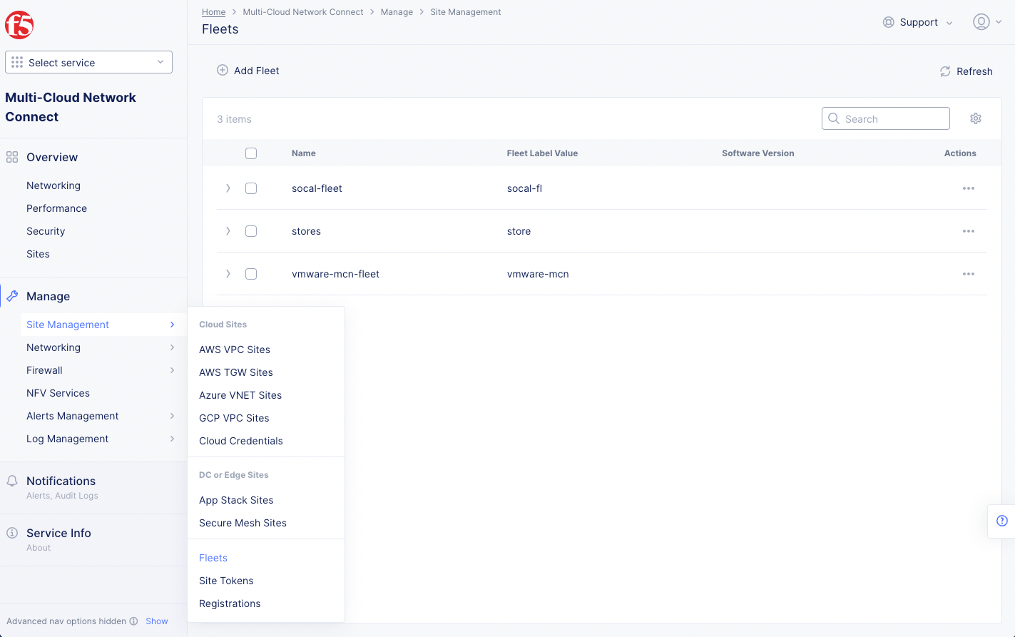
Figure: Fleets
-
Click
...>Manage Configurationfor the fleet you want to manage the USB devices. -
Click
Edit Configuration.
Step 2: Start configuring the USB device policy.
- In the
Advanced Configurationsection, enable theShow Advanced Fieldsoption.
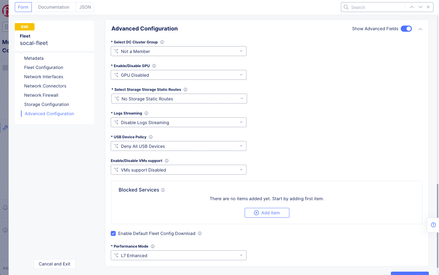
Figure: Enable Show Advanced Fields
-
Select an option from the
USB Device Policymenu and perform configuration per the following guidelines:-
Select
Deny All USB Devicesto deny all USB devices for your sites. This option is selected by default. -
Select
Allow All USB Devicesto allow all USB devices for your sites. -
Select
USB Device Policyto apply an existing USB device policy or create a new one.
-
This example creates a new USB device policy from within fleet configuration and applies it to a fleet.
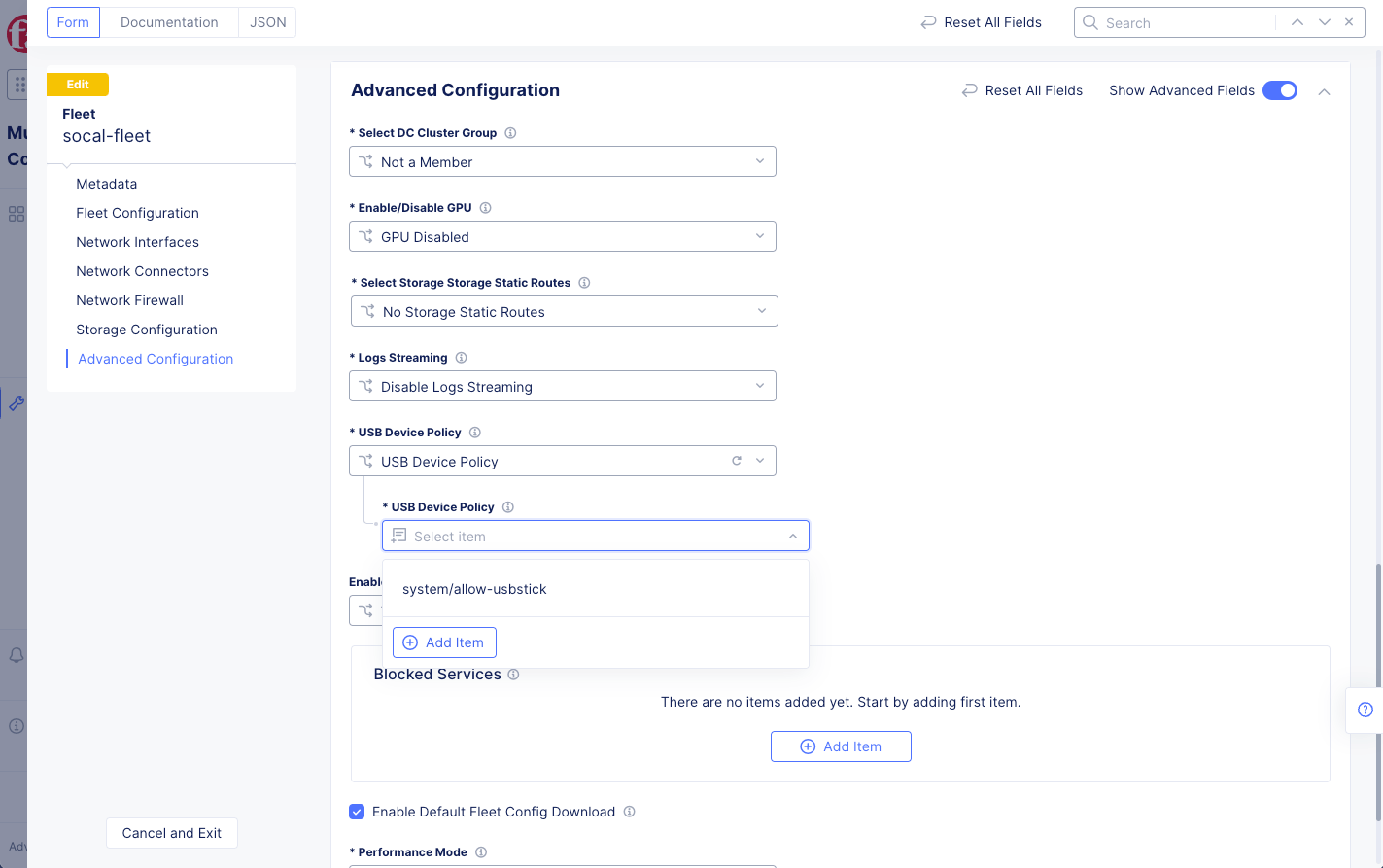
Figure: Fleet USB Policy
-
Select
USB Device Policyfrom the drop-down list. -
From the
USB Device Policymenu, selectAdd Item. This opens the USB device policy creation form.
Step 3: Create a USB device policy.
-
In the
Metadatasection, enter a name for the USB device policy. -
Optionally, add a description and labels.
-
In the
Allowed USB devicessection, clickConfigure. -
Click
Add Item. -
Configure the fields per the following guidelines:
-
In the
iSerialNumberfield, enter an index for the serial number for your device. -
In the
Vendor IDfield, enter the device vendor identifier. -
In the
Product IDfield, enter the device product identifier assigned by the manufacturer. -
In the
Classfield, enter the device class. -
In the
Subclassfield, enter the device subclass. -
In the
Protocolfield, enter the protocol for this device. -
After you finish, click
Add Item.
-
-
Click
Apply. You can add more than one device using theAdd Itemoption. -
Click
Continue. -
Click
Save and Exit. -
To obtain the USB device properties using the site dashboard:
-
Navigate to
Overview>Sites. -
Click on your site to open its dashboard.
-
Click on the
Toolstab. -
Select
Show USB devicesoption from theSelect toolfield. -
Select a node from the list under the
Node namefield.
-
Step 4: Complete updating the fleet configuration.
-
In the
Enable Default Fleet Config Downloadsection, enable theShow Advanced Fieldsoption. -
Click on the
Enable Default Fleet Config Downloadcheckbox. -
Click
Save and Exitto apply the USB device policy to the sites that are part of the fleet.
Concepts
On this page:
- Objective
- Associating Fleet with Site
- Fleet and Virtual Site
- Prerequisites
- Create Fleet
- Apply Fleet Label to Site
- Fleets Tab
- Upgrade Sites Using Fleet
- Upgrade a Fleet
- Configure Multi-Node Site Network Using Fleet
- Configuration Diagram
- Configure Storage in Fleet
- Procedure
- Manage USB Devices Using Fleet
- Apply USB Device Policy Using Fleet
- Concepts