Deploy Secure Mesh Site v2 on F5 BIG-IP rSeries Appliance (ClickOps)
Objective
This guide provides instructions on how to create an F5® Distributed Cloud Customer Edge (CE) on an F5 rSeries Appliance using the Secure Mesh Site via F5 Distributed Cloud Console. For more information on a CE Site, refer to F5 Distributed Cloud - Customer Edge.
Important: This guide does not provide instructions on how to deploy an F5 rSeries Appliance. For more information, see F5 rSeries Documentation. This guide does not provide instructions on how to deploy an F5® App Stack Site. This functionality is in Early Access (EA) and can be used for PoC/PoV deployments. This will be made Generally Available (GA) over the next couple of releases. Please reach out to your account representative for more information.
Prerequisites
The following general prerequisites apply:
-
A Distributed Cloud Services Account. If you do not have an account, see Getting Started with Console.
-
A valid F5 rSeries license and an F5 Distributed Cloud subscription in order to successfully deploy CE.
-
The F5 rSeries appliances should be running F5OS v1.8.0 or above.
-
The F5 rSeries model should be from this list: 5600 / 5800 / 5900/ 10600 / 10800 / 10900 / 12600 / 12800 / 12900.
-
Resources required per node: Minimum 4 vCPUs, 14 GB RAM, and 80 GB disk storage. For a full listing of the resources required, see the Customer Edge Site Sizing Reference guide. All the nodes in a given CE Site should have the same resources regarding the compute, memory, and disk storage. When deploying in cloud environments, these nodes should use the same instance flavor.
-
Allow traffic from and to the Distributed Cloud public IP addresses to your network and allowlist related domain names. See Firewall and Proxy Server Allowlist Reference guide for the list of IP addresses and domain names.
-
F5 assumes that an existing IPv4 subnet exists with Internet connectivity to attach to node(s) to Distributed Cloud SaaS services.
-
Each CE node supports up to eight (8) interfaces. Each interface is required to be in a different subnet. Therefore, make sure you have the required subnets available before creating the CE Site nodes.
-
Internet Control Message Protocol (ICMP) needs to be opened between the CE nodes on the Site Local Outside (SLO) interfaces. This is needed to ensure intra-cluster communication checks.
Important: After you deploy the CE Site, the IP address for the SLO interface cannot be changed. Also, the MAC address cannot be changed.
Configuration Overview
To create a CE Site with F5 rSeries Appliance, here are the high-level steps:
- Create site: Create a Secure Mesh Site using F5 Distributed Cloud Console.
- Download and upload image: Download the node image from the configured Secured Mesh Site using the Distributed Cloud Console, and then upload this image to the F5 rSeries Appliance.
- Deploy site: Utilize the CE image and create a CE node as a Tenant using the
Generic Tenant Deploymentcapabilities of F5 rSeries.
Procedure
In this guide, the procedure demonstrates the steps to deploy a CE node with single and dual interfaces. For sites with multiple nodes, repeat the steps outlined in the Create a CE Node as a Tenant Deployment (VM) on an F5 rSeries Appliance section.
Create Site Object
-
Create a secure mesh site object in Distributed Cloud Console. Refer to the Create Secure Mesh Site guide.
-
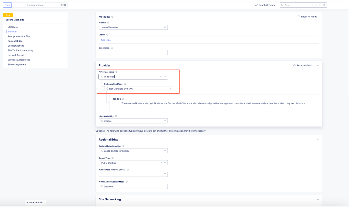
Set the
Provider Nameoption toF5 rSeries. TheOrchestration Modesets toNot Managed by F5XC(also known as manual mode).

Figure: Provider Type
- For the
High Availabilityoption, refer to the Create Secure Mesh Site guide for information on the feature.

Figure: High Availability
Note: All other configuration options have intelligent default values and do not need further configuration. Refer to the Create Secure Mesh Site guide for more information on these options.
- Click
Save and Exit.
Download CE Node Image
-
For the created site object, under
Actions, click.... Then see the following options:-
To download the image file locally, click
Download Image. -
Alternatively, click
Copy Image Nameto receive a download link to use for CLI with thecurlorwgetcommands.
-
Important: The CE image needs to be downloaded once for every site and can be used to deploy multiple nodes.

Figure: Copy or Download rSeries Image
- Verify the integrity of the image file using MD5SUM. See screenshot:

Figure: Verify Integrity of Image
Upload the Image to F5 rSeries Appliance
Use the downloaded image and upload it to the F5 rSeries appliances where the CE nodes will be created.
Important: The CE image is signed and trusted by F5OS.
Step 1: Upload image.
-
In F5OS Console, navigate to
TENANT MANAGEMENT>Tenant Images. -
Click
Upload.

Figure: F5OS Console
- Select the image file to upload.
Step 2: Confirm status.
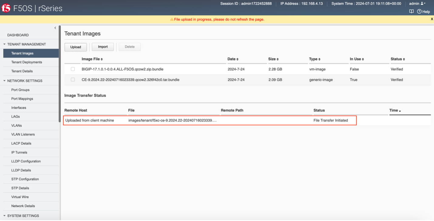
Confirm the file transfer status, and then wait for a successful CE image file upload.

Figure: F5OS Console

Figure: F5OS Console

Figure: F5OS Console
Create a CE Node as a Tenant Deployment (VM) on an F5 rSeries Appliance
Important: The name of the VM should not have
.in it. For example, the hostname can benode-0ornode0, but it cannot benode.f5.comsince it is not supported. If configuring a multi-node site, each node hostname must be unique.
-
Navigate to
TENANT MANAGEMENT>Tenant Images>Tenant Deployments. -
Click
Addto create a CE node as a tenant deployment on F5 rSeries. A CE node will be deployed as a virtual machine on F5 rSeries appliance. -
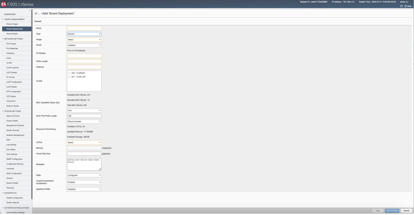
Select
Genericas aTypefor CE deployment.

Figure: Deployment
Connect CE Node Hosted on F5 rSeries to F5 Distributed Cloud SaaS
Customer Edge (CE) nodes require connectivity to F5 Distributed Cloud using the public Internet. To facilitate this, the first interface associated with the CE node must be connected to an IPv4 subnet with connectivity to the public Internet. The CE nodes will be deployed as a Generic VM on F5 rSeries. Traffic originating from this interface on a CE node must be allowed to access F5 Distributed Cloud services.
Refer to the Distributed Cloud Services Firewall and Proxy Server Allowlist Reference for more information.
Prepare Node VM Metadata
Prepare metadata that is required for the CE node to successfully bootstrap and connect to F5 Distributed Cloud.
Use the following format to send the metadata to the CE node VM:
[key1:value1 key2:value2]
There are two mandatory fields (keys) that need to be entered:
primary-vlan: Enter the VLAN ID of the first interface attached to this VM. This interface/VLAN should have access to the public Internet in order to connect to F5 Distributed Cloud.
token: Checkout a node token from F5 Distributed Cloud Console. See Generate Node Token section for details.
[primary-vlan:<VLAN_ID> token:<TOKEN>]
See sample configuration:
[primary-vlan:251 token:eyJhbGciOiJIUzI1NiIsInR5cCI6IkpXVCJ9.eyJzaXRlX25hbWUiOiJjZS1vbi1mNS1yc2VyaWVzIiwidGVuYW50X25hbWUiOiJwbGF5Z3JvdW5kLXd0cHB2YW9nIiwidG9rZW5fdXVpZCI6ImQwMTE5ZjBkLTJkMDItNGUzYy1iZTZlLWYyYTNmMDEyMDVkMSIsImh0dHBfcHJveHkiOiIxMy41MC4yOS4yMzA6NDQzIiwicmVnaXN0cmF0aW9uX3VybCI6InN0YWdpbmcudm9sdGVycmEudXMiLCJpc3MiOiJGNSBYQyBTaXRlIE1hbmFnZXIiLCJzdWIiOiJGNSBYQyBTaXRlIFRva2VuIiwiZXhwIjoxNzIyNTM4NjE0LCJpYXQiOjE3MjI0NTIyMTR9.xsFPM0OPqIyd4RhTucSjFnxM6XGsVRH5S2W7pnsWXYZ]
The following optional fields (keys) can be sent:
slo_dns: Enter the DNS servers to be configured. For example, [primary-vlan:<VLAN_ID> token: <TOKEN> slo_dns:1.1.1.1,2.2.2.2]. Note that this option works when static IP is used. By default, the CE node will use 8.8.8.8 as the DNS server.
Note: DNS works for static IP addresses. DNS IP addresses entered in F5OS Console metadata will not work when DHCP is enabled and DHCP provides the DNS IP address. The DHCP-provided DNS IP address overrides the DNS IP address entered in F5OS Console metadata.
Generate Node Token
A one-time node token is required to register a CE Site node to the Distributed Cloud Console. A new token must be generated for every new node in a CE Site. A token is valid for 24 hours. Make sure that the CE node is deployed soon after the token is generated.
-
In Distributed Cloud Console, select the
Multi-Cloud Network Connectservice. -
Navigate to
Manage>Site Management>Secure Mesh Sites v2. -
For your site, click
...>Generate Node Token.

Figure: Node Token
-
Click
Copy. -
Save the value locally. This token will be used later. The token value is hidden for security purposes.

Figure: Copy Node Token
- Click
Close.
Important: A new token must be generated for every new node in a CE Site. The token is valid for 24 hours. Make sure that the CE node is deployed soon after the token is generated.
Sample CE Tenant Deployments
This section provides a sample configuration to create a CE node as a Generic tenant deployment on F5 rSeries (F5OS) GUI and CLI.
One interface configuration using GUI
Important: The first network provided (primary VLAN) must have Internet connectivity. Provide an IPv4 address. Currently, IPv6 is not supported for connecting the CE node to F5 Distributed Cloud.
- Select the CE image that was uploaded.
- Select a VLAN.
- If you are using DHCP, set DHCP to enable. If using static configuration, set DHCP to disabled and then provide
IP Address,Prefix LengthandGateway. - Ensure MAC address is set to small size (8).
- Select the vCPUs and set Virtual Disk size (minimum 50 GB). Refer to the Customer Edge Site Sizing Reference guide.
- Enter the metadata.
- Change state to
Deployed. - Click
Save.

Figure: Interface Configuration with GUI
One interface configuration using CLI
Important: The first network provided (primary VLAN) must have Internet connectivity. Provide an IPv4 address. Currently, IPv6 is not supported for connecting the CE node to F5 Distributed Cloud.
- Prepare the CE node tenant deployment configuration. Choose the uploaded CE image.
cat tenant.create.api.data.txt
{
    "tenant": [
        {
            "name": <CE_NODE_NAME>,
            "config": {
                "type": "GENERIC",
                "image": <UPLOADED_CE_IMAGE>,
                "nodes": [
                    1
                ],
                "dhcp-enabled": true,
                "dag-ipv6-prefix-length": 128,
                "vlans": [
                    251
                ],
                "vcpu-cores-per-node": 4,
                "memory": 14848,
                "storage": {
                    "size": 50
                },
                "cryptos": "enabled",
    "mac-data": {
                    "f5-tenant-l2-inline:mac-block-size": "small"
                },
                "running-state": "deployed",
                "f5-tenant-metadata:metadata": [
                    "primary-vlan:251",
"token:eyJhbGciOiJIUzI1NiIsInR5cCI6IkpXVCJ9.eyJzaXRlX25hbWUiOiJzcmktcnNlcmllcy10ZXN0LTE0IiwidGVuYW50X25hbWUiOiJwbGF5Z3JvdW5kLXd0cHB2YW9nIiwidG9rZW5fdXVpZCI6IjFkMDRmY2Y2LWMwYzItNDg1ZS1hZDk4LWEwNmY1MGE3ZmI3NiIsImh0dHBfcHJveHkiOiIzNC4yMjYuOTguMjEzOjgwODAiLCJyZWdpc3RyYXRpb25fdXJsIjoic3RhZ2luZy52b2x0ZXJyYS51cyIsImlzcyI6IkY1IFhDIFNpdGUgTWFuYWdlciIsInN1YiI6IkY1IFhDIFNpdGUgVG9rZW4iLCJleHAiOjE3MjIzODA5NTIsImlhdCI6MTcyMjI5NDU1Mn0.VZwO0gSbD1AiQA-wbHep_DrVC7-93EEYOEZ4-7ggz3c"
                ]
            }
        }
    ]
}
- To create the CE tenant, use the
curlcommand to execute the following:
curl -k -X POST -H "Content-Type: application/yang-data+json" --data-binary "@<PATH_TO_CE_NODE_TENANT_DEPLOYMENT_CONFIG_FILE>" -H "Accept: application/yang-data+json" -u <admin:password> 'https://<F5_RSERIES_IP:PORT>/restconf/data/f5-tenants:tenants'
Two-interface configuration using GUI
Important: The first network/VLAN provided (primary VLAN) must have Internet connectivity. Provide an IPv4 address. Currently, IPv6 is not supported to connect the CE node to F5 Distributed Cloud. The second network/VLAN can be used for other networks (SLI - Local VRF or Segment - Global VRF). Interfaces added after the first interface will default to the SLI VRF and will need to be configured from site configuration from the F5 Distributed Cloud Console, after addition.
- Select the CE image that was uploaded.
- Select two VLANs: one to be used to connect the CE node with F5 Distributed Cloud (requiring Internet access) and another one used for local network.
- If you are using DHCP, set DHCP to enable. If using static configuration, set DHCP to disabled and then provide
IP Address,Prefix LengthandGateway. - Ensure MAC address is set to small size (8).
- Select the vCPUs and set Virtual Disk size (minimum 50 GB). Refer to the Customer Edge Site Sizing Reference guide.
- Enter the metadata.
- Change state to
Deployed. - Click
Save.

Figure: Two-Interface Configuration with GUI
Two-interface configuration using CLI
Important: The first network/VLAN provided (primary VLAN) must have Internet connectivity. Provide an IPv4 address. Currently, IPv6 is not supported to connect the CE node to F5 Distributed Cloud. The second network/VLAN can be used for other networks (SLI - Local VRF or Segment - Global VRF). Interfaces added after the first interface will default to the SLI VRF and will need to be configured from site configuration from the F5 Distributed Cloud Console, after addition.
- Prepare the CE node tenant deployment configuration. Choose the uploaded CE image.
cat tenant.create.api.data.txt
{
    "tenant": [
        {
            "name": <CE_NODE_NAME>,
            "config": {
                "type": "GENERIC",
                "image": <UPLOADED_CE_IMAGE>,
                "nodes": [
                    1
                ],
                "dhcp-enabled": true,
                "dag-ipv6-prefix-length": 128,
                "vlans": [
                    251, 252
                ],
                "vcpu-cores-per-node": 4,
                "memory": 14848,
                "storage": {
                    "size": 50
                },
                "cryptos": "enabled",
    "mac-data": {
                    "f5-tenant-l2-inline:mac-block-size": "small"
                },
                "running-state": "deployed",
                "f5-tenant-metadata:metadata": [
                    "primary-vlan:251",
"token:eyJhbGciOiJIUzI1NiIsInR5cCI6IkpXVCJ9.eyJzaXRlX25hbWUiOiJzcmktcnNlcmllcy10ZXN0LTE0IiwidGVuYW50X25hbWUiOiJwbGF5Z3JvdW5kLXd0cHB2YW9nIiwidG9rZW5fdXVpZCI6IjFkMDRmY2Y2LWMwYzItNDg1ZS1hZDk4LWEwNmY1MGE3ZmI3NiIsImh0dHBfcHJveHkiOiIzNC4yMjYuOTguMjEzOjgwODAiLCJyZWdpc3RyYXRpb25fdXJsIjoic3RhZ2luZy52b2x0ZXJyYS51cyIsImlzcyI6IkY1IFhDIFNpdGUgTWFuYWdlciIsInN1YiI6IkY1IFhDIFNpdGUgVG9rZW4iLCJleHAiOjE3MjIzODA5NTIsImlhdCI6MTcyMjI5NDU1Mn0.VZwO0gSbD1AiQA-wbHep_DrVC7-93EEYOEZ4-7ggz3c"
                ]
            }
        }
    ]
}
- To create the CE tenant, use the
curlcommand to execute the following:
curl -k -X POST -H "Content-Type: application/yang-data+json" --data-binary "@/Users/suser/Downloads/tenant.create.api.data.txt" -H "Accept: application/yang-data+json" -u admin:password 'https://192.168.4.13:8888/restconf/data/f5-tenants:tenants'
- To view the status, navigate to
Tenant Deployments.

Figure: View Tenant Deployment Status
Note: After deploying the CE node tenant, the CE node will be identified and associated with the created Secure Mesh site. Progress of deployment can be observed using the F5 Distributed Cloud UI. The admin state will change from
Waiting for RegistrationtoProvisioning. After some time, the site will have admin status asOnline.

Figure: View Deployment Status
Verify CE Site Registration
-
In Distributed Cloud Console, navigate to
Multi-Cloud Network Connect>Overview>Infrastructure>Sites. -
Select the site. The
Dashboardtab should clearly show that the CE Site has registered successfully with theSystem Healthof 100% as well asData Plane/Control Planeboth being up.
Note: For more information on the site registration process, see the Customer Edge Registration and Upgrade Reference guide.
Add New Network Interface
After the CE Site registers successfully, you might want to add additional interfaces to cater to different customer requirements.
Important: Adding a new network interface will cause the data plane services to restart. Therefore, it is strongly recommended to perform this operation during maintenance windows. As data plane services restart, traffic drops are expected, as well as tunnels going down. All nodes in a given CE site should have the same number of network interfaces attached. Each node in the CE site should have interfaces with the same VRFs assigned. For example: If a CE site has three nodes, each node having two interfaces - the first interface on each node will be auto-configured to be in the SLO VRF (to connect to F5 Distributed Cloud). If the second interface on node-1 is in the SLI VRF, then the second interface on node-2 and node-3 should also be in the SLI VRF.
When adding interfaces, it is important to make sure that the interfaces are added to each node in the cluster. Nodes with non-homogenous interfaces within a CE Site might cause issues. Therefore, each node in a given CE Site should have the same number of interfaces placed in the same VRFs.
Step 1: Attach an interface/VLAN to the CE node tenant deployment from F5 rSeries.
-
From F5 rSeries console, navigate to
TENANT MANAGEMENT>Tenant Deployments. -
Power down the VM prior to adding any new interfaces or modifying any existing interfaces.
-
Edit the CE node tenant deployment and select additional interface(s)/VLAN(s) to attach to the node.

Figure: Attach Interface
-
Power on the VM.
-
Click
Save & Close.
Important: Repeat these steps for all CE node deployments associated with the CE site. Each node in a CE site should have the same number of network interfaces.
Step 2: Configure the newly attached interface/VLAN on the CE node from F5 Distributed Cloud.
-
In the
Multi-Cloud Network Connectservice, clickManage>Site Management>Secure Mesh Sites. -
For the site, click
...>Manage Configuration. Then, in the wizard, clickEdit Configuration.

Figure: Node Edit
- In the
Providersection, click the pencil button to edit the desired node.

Figure: Node Edit
-
Click
Add Itemto add a second interface. -
In the
Metadatasection, enter a name for the new interface. Optionally, add a short description to identify this new interface.

Figure: New Interface Metadata
- In the
Device Configurationsection, from theInterface Typemenu, selectVLAN Interface. Enterenp2s0as theParent Interface.

Figure: New Interface Device Configuration
- Enter VLAN number for the
VLAN ID. The VLAN number should be the same number as assigned to the servers which the interface will communicate with.

Figure: New Interface Device Configuration
-
Configure the
IPv4 Interface Address Methodoption from the following:- DHCP Client
- Static IP

Figure: IP Address

Figure: IP Address
Important: The IP address for the SLO interface cannot be modified. This change can damage cluster configuration.
- Assign interface to a VRF via the
Select VRFoption. The default and most common option isSite Local Inside (Local VRF), but can also be assigned toSegment (Global VRF).
Note: A
SegmentVRF being a global VRF allows stretching networks across CE sites, making it easy to connect networks across data center/branch/public cloud locations.

Figure: VRF Configuration
- Click
Apply.

Figure: Apply Configuration
-
Click
Save and Exit. -
Repeat these steps for additional interfaces.
-
To view the new interface added, navigate to the
Infrastructuretab. TheInterfacessection provides the required information.

Figure: Interfaces View
Troubleshooting
For troubleshooting issues, see the Troubleshooting Guide for Secure Mesh Site v2 Deployment guide. It provides step-by-step instructions to debug and resolve the issues that may arise due to registration and provisioning errors.
Concepts
- System Overview
- Core Concepts
- Networking
- F5 Distributed Cloud - Customer Edge
- F5 Distributed Cloud Site
- F5 Distributed Cloud Customer Edge on F5 rSeries – Reference Architecture
On this page:
- Objective
- Prerequisites
- Configuration Overview
- Procedure
- Create Site Object
- Download CE Node Image
- Upload the Image to F5 rSeries Appliance
- Create a CE Node as a Tenant Deployment (VM) on an F5 rSeries Appliance
- Connect CE Node Hosted on F5 rSeries to F5 Distributed Cloud SaaS
- Prepare Node VM Metadata
- Generate Node Token
- Sample CE Tenant Deployments
- Verify CE Site Registration
- Add New Network Interface
- Troubleshooting
- Concepts