Deploy Secure Mesh Site v2 on Baremetal (ClickOps)
Objective
This guide provides instructions on how to create a Customer Edge (CE) Site using F5® Distributed Cloud Console to deploy on a baremetal server.
Important: This guide does not provide instructions on how to deploy an F5® App Stack Site.
Planning
Read the following documents before deploying a Secure Mesh Site in any provider environment:
- Understanding F5 Distributed Cloud - Customer Edge (CE)
- CE Datasheet
- CE Supported Platforms Guide
- Customer Edge Site Sizing Reference
- CE Performance Guide: Contact your account representative on CE performance-related information.
- Proxy for CE Registration and Upgrades Reference
- Secure Mesh Sites v2 Frequently Asked Questions
- Customer Edge Registration and Upgrade Reference
- F5 Customer Edge IP Address and Domain Reference for Firewall or Proxy Settings
General Prerequisites
The following general prerequisites apply:
-
A Distributed Cloud Services Account. If you do not have an account, see Getting Started with Console.
-
Resources required per node: Minimum 8 vCPUs, 32 GB RAM, and 80 GB disk storage. For a full listing of the resources required, see the Customer Edge Site Sizing Reference guide. All the nodes in a given CE Site should have the same resources regarding the compute, memory, and disk storage. When deploying in cloud environments, these nodes should use the same instance flavor.
-
Customer Edge deployments require connectivity to F5 Distributed Cloud. See the F5 Customer Edge IP Address and Domain Reference for Firewall or Proxy Settings guide for the list of IP addresses and domain names that need to be allowed.
-
F5 assumes that minimum the networks for the Site Local Outside (SLO) and one for the Site Local Inside (SLI).
-
For a single-NIC deployment (ingress gateway), only a single subnet (SLO) is required.
-
The new Secure Mesh Site workflow enables you to have up to eight interfaces. However, these interfaces should be in different subnets. Therefore, make sure you have the required subnets available before creating the CE Site nodes.
-
If you are deploying the CE Site with High Availability (HA) enabled, the Internet Control Message Protocol (ICMP) must be opened between the CE nodes on the Site Local Outside (SLO) interfaces. This is needed to ensure intra-cluster communication checks.
Important: After you deploy the CE Site, the IP address for the SLO interface cannot be changed. Also, the MAC address cannot be changed.
Bond interfaces are not supported.
Supported Hardware
For a listing of supported hardware, see the Customer Edge Site Sizing Reference guide.
Configuration Overview
To create a Secure Mesh Site with baremetal, here are the high-level steps:
- Site object configuration: Create and configure a Secure Mesh Site object using F5 Distributed Cloud Console.
- Node creation prerequisites: Create objects that are associated with the CE nodes, including the networks, IPMI console access, and more.
- Image management: Download the image locally or use a URL for remote machines.
- Node management: Use IPMI console to manage the server and deploy CE nodes. Each CE node is a virtual machine (VM).
- Network interface management: Add additional interfaces on the nodes, if necessary.
Note: This document describes one- and two-interface deployments for CE sites with HA disabled (single node) and HA enabled (three-node cluster).
Procedure
This guide shows you how to deploy a single-node CE Site with dual interfaces (ingress/egress gateway). However, this guide also incorporates the differences that you can follow to successfully deploy a Baremetal CE Site in any supported combination of nodes and interfaces.
Create Secure Mesh Site Object
-
Log into Console.
-
From the Console homepage, select the Multi-Cloud Network Connect workspace.
-
Click Manage > Site Management > Secure Mesh Sites v2.

Figure: Navigate to Secure Mesh Site
- Click Add Secure Mesh Site.

Figure: Create Site Object
- Enter a name for the new Site.

Figure: Set Provider
-
Set the Provider Name option to Baremetal.
-
For High Availability, choose an option. If it is Disabled, then the CE Site only supports one node. If it is Enabled, the CE Site requires three nodes. Additional nodes can only be added to CE sites when HA is Enabled.
Important: The High Availability mode cannot be changed after the CE Site is created.

Figure: High Availability
-
Leave the other options with their default values. These options have intelligent default values and do not need further configuration. Refer to the Create Secure Mesh Site guide for more information on these options.
-
Click Add Secure Mesh Site.
Download Node Image
The Distributed Cloud CE node software is packaged into an ISO image file.
The ISO filename follows this naming convention: f5xc-ce-<version>-securemeshv2-<timestamp>. For example, f5xc-ce-9.2024.22-securemeshv2-20240711-0205.iso. This ISO image is used to bootstrap baremetal nodes.
- To download the image file locally, click ... > Download Image.

Figure: Download Image File
- Ensure that you validate the MD5SUM of the image for an integrity check, and then click Close.
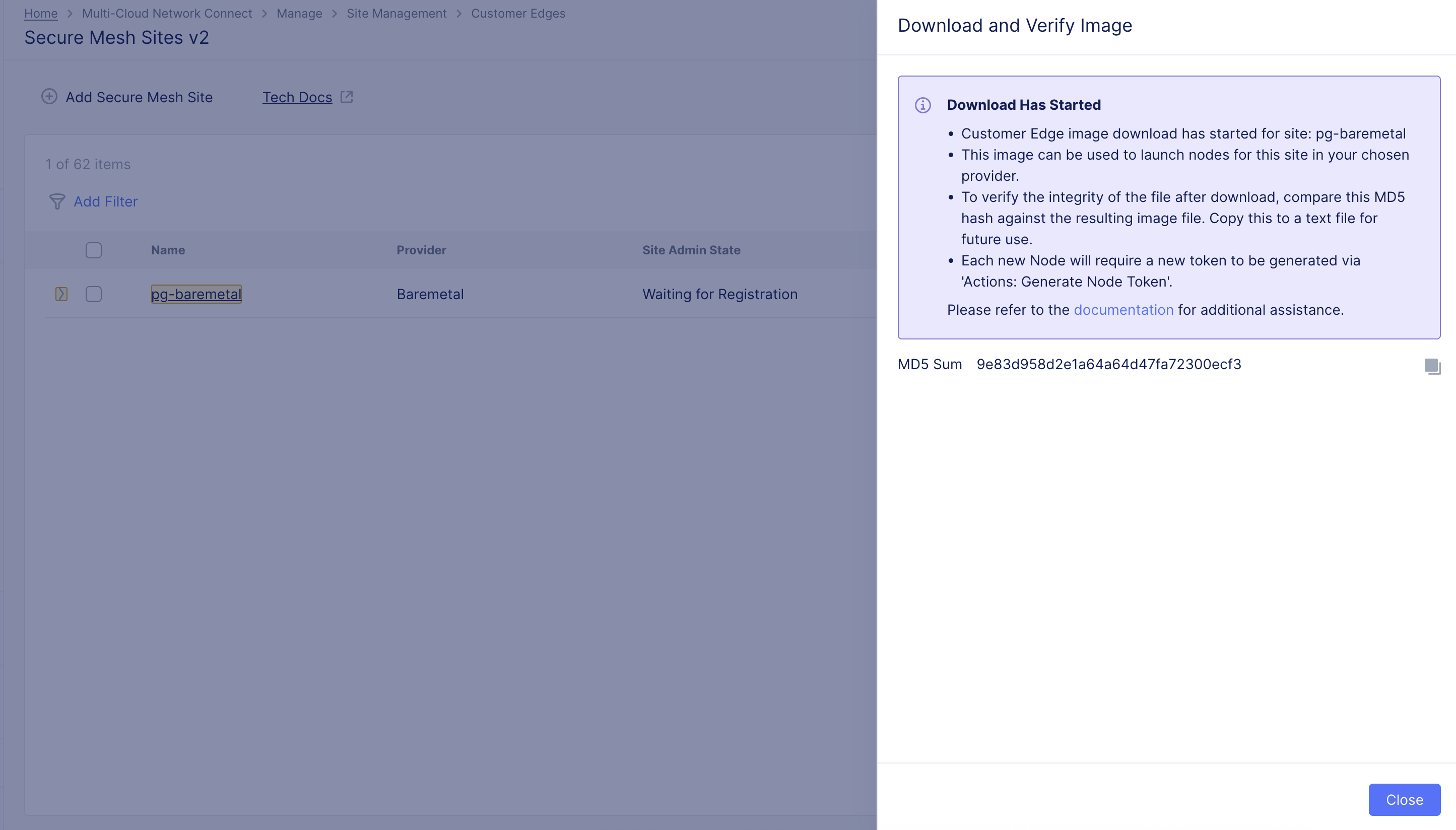
Figure: Validate Image File
- Optionally, Under Actions, click ... > Copy Image Name to receive a download link to use for CLI with the curl or wget commands.
Generate Node Token
A one-time node token is required to register a CE Site node to the Distributed Cloud Console. A new token must be generated for every new node in a CE Site. A token is valid for 24 hours. Make sure that the CE node is deployed soon after the token is generated.
-
In Distributed Cloud Console, select the Multi-Cloud Network Connect workspace.
-
Navigate to Manage > Site Management > Secure Mesh Sites v2.
-
For your Site, click ... > Generate Node Token.
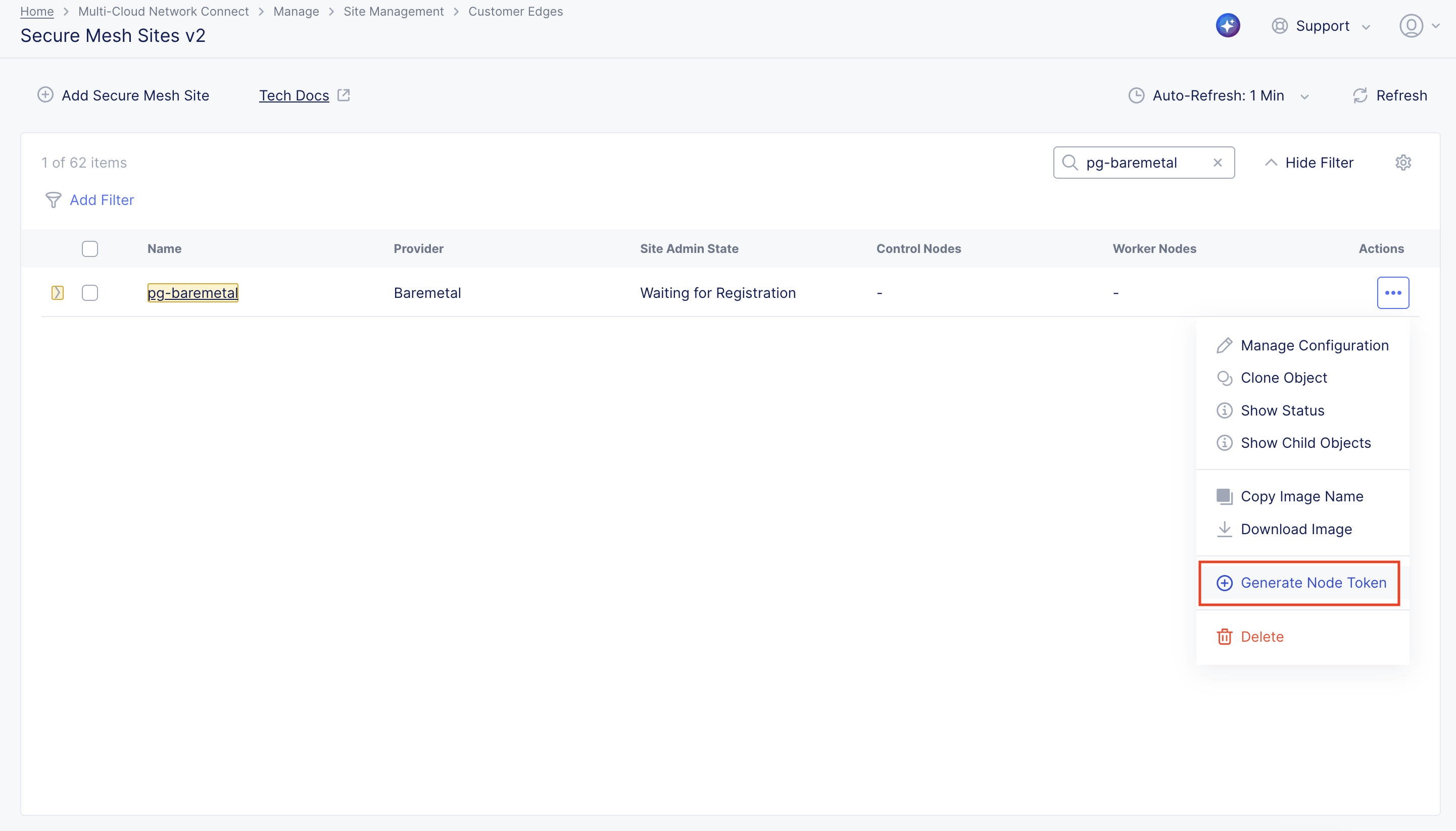
Figure: Generate Node Token
- Click Copy Token and save the value locally. This token is used later. The token value is hidden for security purposes.

Figure: Copy Token
- Click Close.
Create CE Node
This section provides two methods to create and boot a CE node: (1) Virtual CD/DVD and (2) USB. The instructions for attaching media and booting are for a specific vendor. Other vendors may differ. Refer to the respective vendor's documentation for proper operation.
Important: The name of the VM should not have "." in it. For example, the hostname can be node-0 or node0, but it cannot be node.f5.com since it is not supported. Your node VM name must adhere to DNS-1035 label requirements. This means the name must consist of lower case alphanumeric characters or “-“, start with an alphabetic character, and end with an alphanumeric character.
If configuring a multi-node site, each node hostname must be unique.
You must connect at least one interface of each CE node to an IPv4 subnet with connectivity to the Internet.
By default, the CE node uses a proxy hosted by F5 Distributed Cloud that is automatically configured. This can be changed to a customer-owned enterprise proxy.
None of the interfaces should have an IP address from the 169.254.0.0/16 range, whether assigned manually or via DHCP. Note that some USB NICs may automatically receive IP addresses from this range. This behavior should be disabled in the BIOS.
Boot Node Using Virtual CD or DVD
- Attach the downloaded ISO image file to the Virtual CD/DVD.
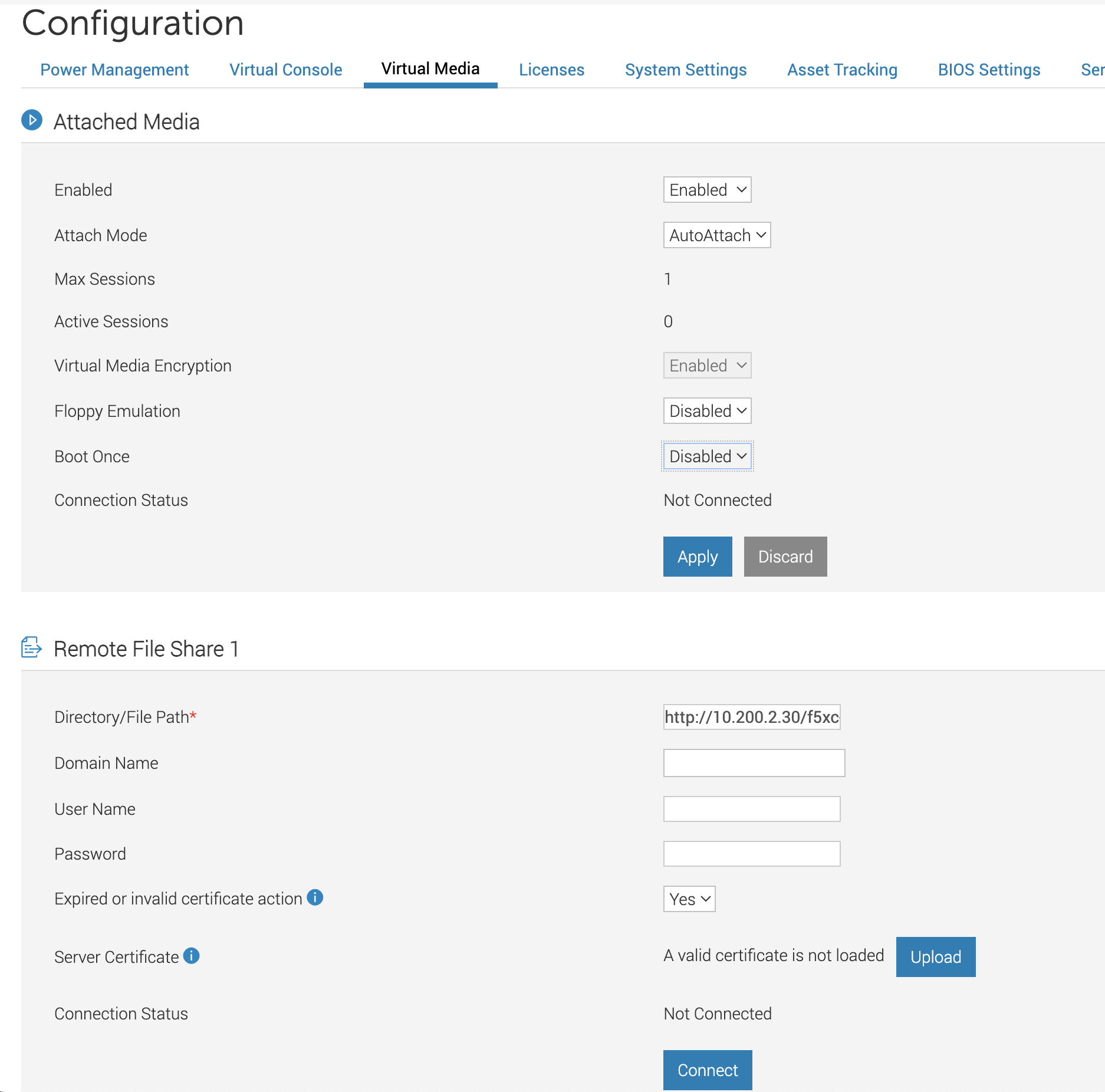
Figure: Attach to Virtual CD/DVD
- Set Virtual CD/DVD/ISO as a one-time boot option.
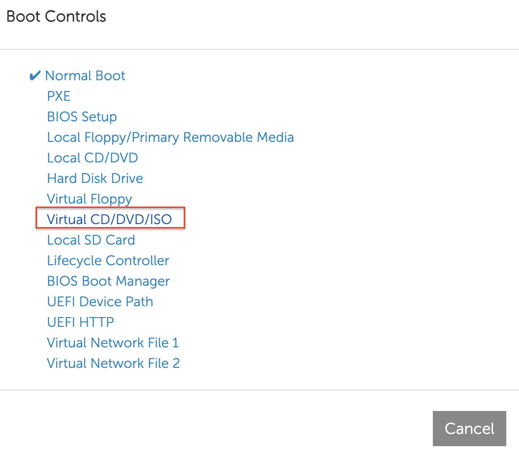
Figure: Set One-Time Boot Option
Boot Node Using USB
-
Copy the ISO image file onto the USB, making it bootable. Use this procedure to create a bootable USB.
-
Set the USB/removable media as a one-time boot option.
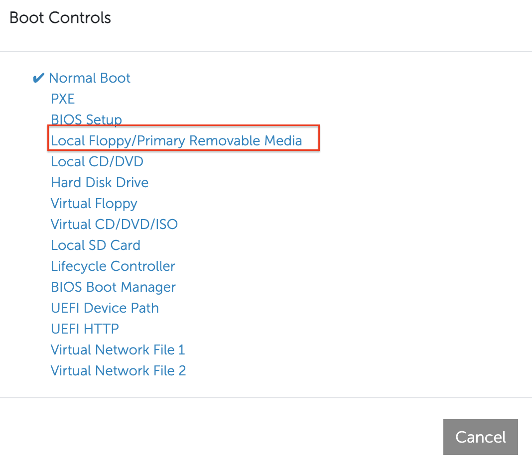
Figure: Set One-Time Boot Option
Install Node OS Software
After you boot the CE node using one of the two options above, a prompt appears with instructions to install the Distributed Cloud Services node OS. Note that the installation process is fully automated.
- Use the keyboard arrows to select Install RHEL 9 for securemeshv2. This is the recommended option.
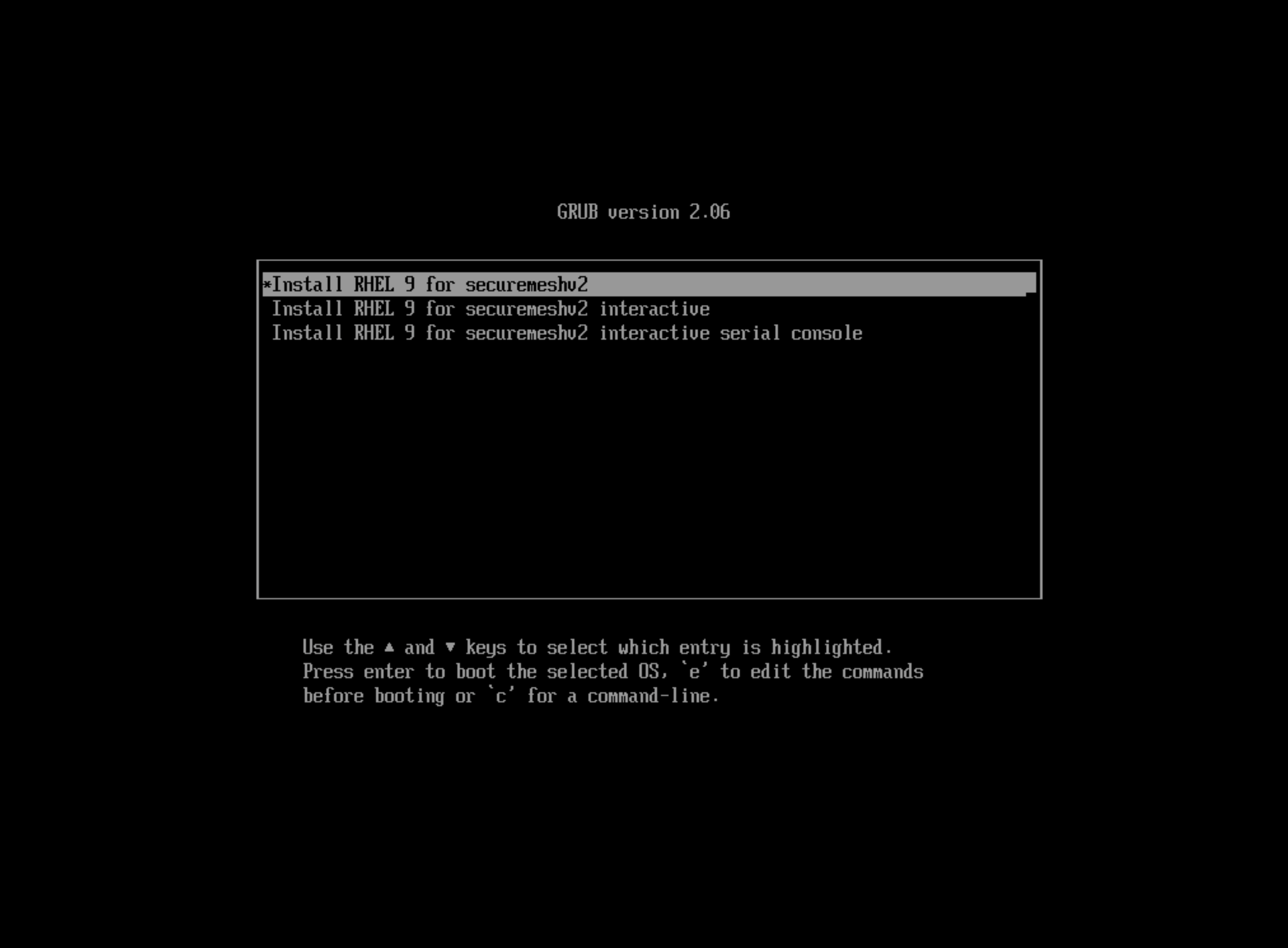
Figure: Recommended Option
- After the installation process is complete, log in to the prompt.
Configure Node Parameters
Log in to the node to configure additional options.
Step 1: Log in to the node. Access the node using SSH or through a console window.
-
Log in to the node with the default user credentials:
- Local user account is admin with password Volterra123.
- If this is the first time you are logging in, you are prompted to update the default password for the admin user account. Follow the instructions to update the default password.
-
Press the Tab key to select parameters to configure.
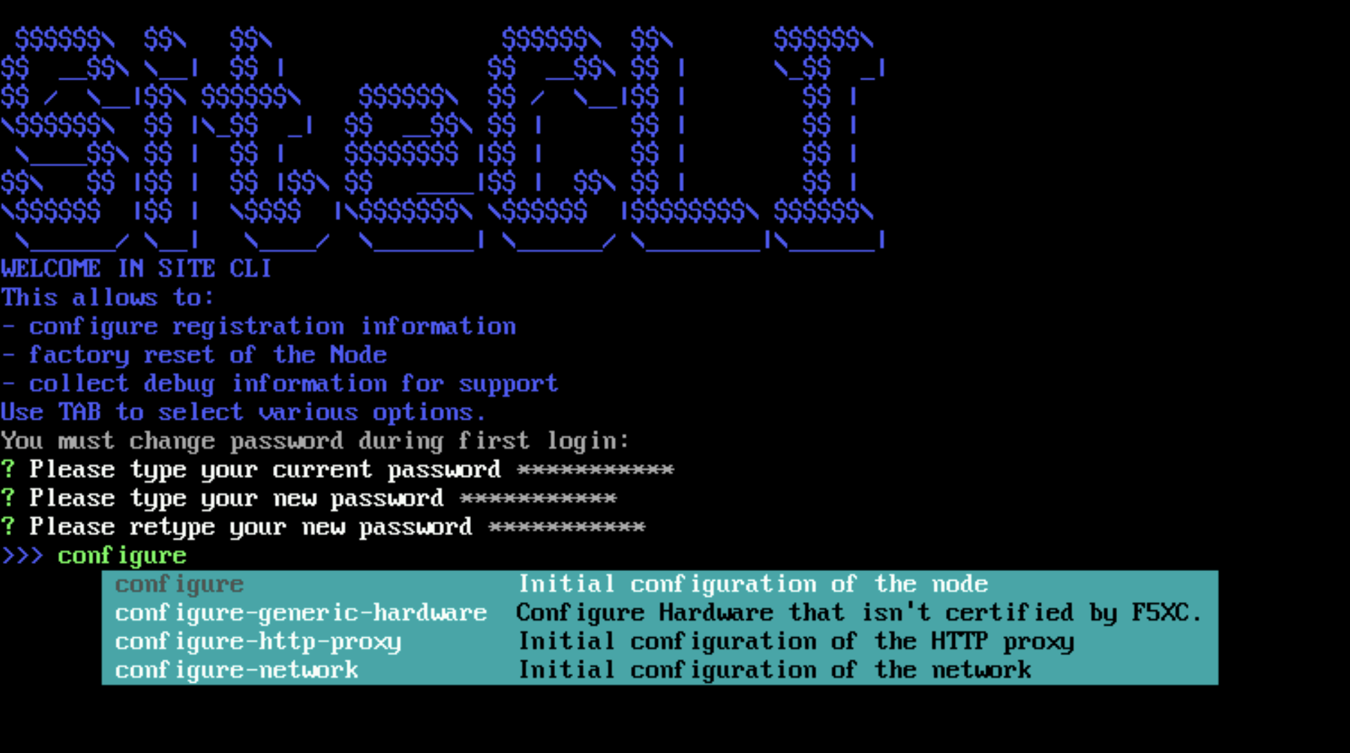
Figure: Configure Node
Step 2: Optionally, start network configuration.
Use this option if you want to use a static IP address instead of DHCP.
Use configure-network to perform the following tasks:
- Configure static IP (need to reflect to configuration in Console UI)
- Special DNS, NTP, and so on
- Configure a proxy
- If you use an NTP server, ensure that the server is reachable. Otherwise, leave the NTP server configuration empty so that the F5 Distributed Cloud NTP servers are used instead.
Note: You cannot change an IP address for a registered node in a multi-node site. You must use fixed IP addresses or DHCP addresses with a fixed lease. When you configure an HTTP proxy server, IPsec tunneling is not supported. For tunneling, use SSL or automatic.

Figure: Network Configuration
Step 3: Configure the main options.
Note: If you apply static configuration for the network, you must first perform network configuration using the configure-network option before you set additional fields using the configure option. Also, you cannot change the IP address of a node in a multi-node site after the node is successfully registered.
-
Press the Tab key to select the configure option.
-
Enter the registration token.
-
Enter a hostname.
Important: Ensure that hostnames are unique if you are installing nodes for a multi-node site. The hostname must be the same as the hostname provided in the Distributed Cloud Console.
-
Select an option for the certified hardware. Do not change the default value (site-v2-generic-chw) unless requested by the F5 Distributed Cloud Support Team.
-
Select NIC with Internet access. This network interface must have Internet connectivity and is used to establish tunnels to the F5 Distributed Cloud Regional Edges.
-
Confirm configuration. Enter Y to confirm configuration. This triggers the registration process on Distributed Cloud global controllers.
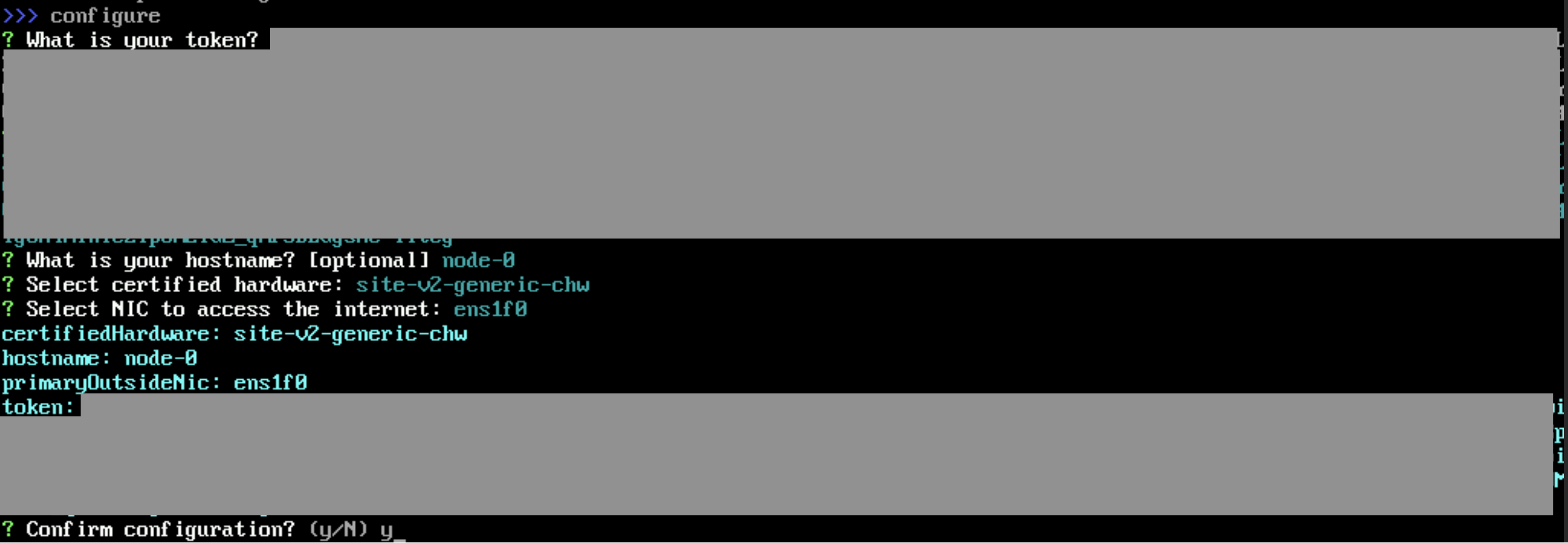
Figure: Configure Main Options
Step 4: Verify CE Site registration.
-
Navigate to Overview > Infrastructure > Sites and choose your new Site from the Sites list at the bottom of the dashboard.
-
Confirm the CE Site has registered successfully with the System Health of 100 as well as Data Plane and Control Plane both being up.

Figure: Site Successfully Registered
- Click the Infrastructure tab to see the Nodes and Interfaces with their IP addresses.

Figure: Node Infrastructure
Note: For more information on the site registration process, see the Customer Edge Registration and Upgrade Reference guide.
Manage Network Interfaces (Optional)
After your CE Site registers successfully, you might want to add additional network interfaces to meet your requirements. Ensure that you connect another network interface to the node VM.
Important: Adding or removing network interfaces causes the data plane services on the CE node to restart. Therefore, F5 strongly recommends that you perform this operation during maintenance windows. As data plane services restart, traffic drops are expected, as well as tunnels to F5 Distributed Cloud REs going down.
All CE nodes in a given CE Site should have the same number of network interfaces attached. CE nodes with non-homogenous interfaces within a CE Site might cause issues.
Each node in the CE Site should have interfaces with the same VRFs assigned. For example: If a CE Site has three nodes, with each node having two interfaces - the first interface on each node is auto-configured to be in the SLO VRF (to connect to F5 Distributed Cloud). If the second interface on node-1 is in the SLI VRF, then the second interface on node-2 and node-3 must also be in the SLI VRF.
When new interfaces are added, they are auto-discovered. You can configure the interface (for example: place the interface in the appropriate VRF) from the CE Site configuration.
The first interface of the CE nodes should not be removed or modified.
After you configure the SLO interface with a static IP address, DHCP will still be displayed in the Console. However, your static IP configuration is well taken into account. Also, remember that you cannot modify SLO parameters once the node is registered and deployed.
Add New Interface
Attach additional network interface(s) to the CE nodes. Make sure to maintain homogeneity. As in, add the same number of interfaces mapped to the same port groups on all CE nodes (VMs). Power off your node before adding a new interface. Note that bond interfaces are not supported.
Modify Interface Attributes
Step 1: Modify interface.
-
Power off all CE nodes (VMs) of your CE Site prior to modifying any existing interfaces.
-
In the Multi-Cloud Network Connect workspace, click Manage > Site Management > Secure Mesh Sites v2.
-
For your Site, click ... > Manage Configuration.
-
Click Edit Configuration.
-
In the Provider section, click the pencil button to edit the desired node.
-
Click the pencil button next to the newly discovered interface. The MAC address is shown in the table for convenience.
Note: Interface Name is not a mandatory field but is recommended to be configured.
-
Select the un-configured network device that is detected by the node by clicking See Suggestions.
-
From the IPv4 Interface Address Method menu, select the IP address configuration from the following options:
- DHCP Client
- Static IP
Important: The IP address for the SLO interface cannot be changed. This change can damage the cluster configuration.
-
Assign interface configurations for the Select VRF option to VRF. The default and most common option is Site Local Inside (Local VRF), but can also be assigned to Segment (Global VRF).
-
Click Apply. Then, click Apply again.
Step 2: Verify changes in Distributed Cloud Console.
-
Click Save Secure Mesh Site to complete the Secure Mesh Site configuration.
-
Power on the CE nodes (VMs). The CE Site resource in Distributed Cloud Console auto-detects changes in the interfaces.
-
To view the interface details, navigate to the Infrastructure tab in the CE Site dashboard.
Day 2 Operations
- To monitor your Site, see the Monitor Site guide.
- To manage your Site software and OS updates, see the Manage Site guide.
- For troubleshooting issues, see the Troubleshooting Guide for Secure Mesh Site v2 Deployment guide. It provides step-by-step instructions to debug and resolve the issues that may arise due to registration and provisioning errors.
- For the latest on Distributed Cloud Services releases, see Changelogs.
- To view the various types of events generated, see the Events Reference guide.
Related Guides
To create a load balancer on the CE Site, see the HTTP Load Balancer or the TCP Load Balancer guides.
Concepts
On this page:
- Objective
- Planning
- General Prerequisites
- Supported Hardware
- Configuration Overview
- Procedure
- Create Secure Mesh Site Object
- Download Node Image
- Generate Node Token
- Create CE Node
- Boot Node Using Virtual CD or DVD
- Boot Node Using USB
- Install Node OS Software
- Configure Node Parameters
- Manage Network Interfaces (Optional)
- Add New Interface
- Modify Interface Attributes
- Day 2 Operations
- Related Guides
- Concepts