Deploy Secure Mesh Site v2 on VMware (ClickOps)
Objective
This guide provides instructions on how to create a customer edge (CE) site using the F5® Distributed Cloud Console for VMware.
Important: This guide does not provide instructions on how to deploy an F5® App Stack Site.
Planning
Read the following documents before deploying a Secure Mesh Site in any provider environment:
- Understanding F5 Distributed Cloud - Customer Edge (CE)
- CE Datasheet
- CE Supported Platforms Guide
- Customer Edge Site Sizing Reference
- CE Performance Guide: Contact your account representative on CE performance-related information.
- Proxy for CE Registration and Upgrades Reference
- Secure Mesh Sites v2 Frequently Asked Questions
- Customer Edge Registration and Upgrade Reference
- F5 Customer Edge IP Address and Domain Reference for Firewall or Proxy Settings
General Prerequisites
The following general prerequisites apply:
-
A Distributed Cloud Services Account. If you do not have an account, see Getting Started with Console.
-
VMware vSphere Hypervisor (ESXi) 7.0 or later. The examples in this document are based on version 7.0.0.
-
At least one interface in your VMWare ESXi environment with Internet connectivity.
-
Resources required per node: Minimum 8 vCPUs, 32 GB RAM, and 80 GB disk storage. For a full listing of the resources required, see the Customer Edge Site Sizing Reference guide. All the nodes in a given CE Site should have the same resources regarding the compute, memory, and disk storage. When deploying in cloud environments, these nodes should use the same instance flavor.
-
Customer Edge (CE) deployments require connectivity to F5 Distributed Cloud. See the F5 Customer Edge IP Address and Domain Reference for Firewall or Proxy Settings guide for the list of IP addresses and domain names that need to be allowed.
-
The new Secure Mesh Site workflow enables you to have up to eight interfaces. However, these interface should be in different subnets. Therefore, make sure you have the required subnets available before creating the CE Site nodes.
-
If deploying the CE site with High Availability (HA) enabled, Internet Control Message Protocol (ICMP) must be opened between the CE nodes on the Site Local Outside (SLO) interfaces. This is needed to ensure intra-cluster communication checks.
Important: After you deploy the CE Site, the IP address for the SLO interface cannot be changed. Also, the MAC address cannot be changed.
Note that this document describes one- and two-interface deployments for CE sites with HA-disabled (single-node) and HA-enabled (three-node cluster).
Configuration Overview
To create a Secure Mesh Site with VMware, here are the high-level steps:
- Site object configuration: Create and configure a Secure Mesh Site object using F5 Distributed Cloud Console.
- Image management: Download the software image (VMware OVA) from the F5 Distributed Cloud Console.
- Node management: Use the downloaded OVA image to launch CE nodes. Each CE node is a virtual machine (VM).
- Network interface management: Add additional interfaces on the nodes, if necessary.
Important: The first interface of a CE node must be mapped to the Site Local Outside (SLO) VRF, which should allow connectivity to F5 Distributed Cloud.
Procedure
This guide explains how to deploy a single-node secure mesh site with dual interfaces, including deviations from this specific model, where necessary, to adjust to different node and interface requirements.
Create Site Object
Create a secure mesh site object in the Distributed Cloud Console and select VMware as the provider.
Step 1: Enter metadata information for site.
-
In Distributed Cloud Console, select Multi-Cloud Network Connect.
-
Navigate to Manage > Site Management > Secure Mesh Sites v2.
-
Select Add Secure Mesh Site to open the configuration form.
-
In the Metadata section, enter a name for the site.
-
Optionally, select labels and add a description.
Step 2: Select the provider name as VMware.
-
Set the Provider Name option to VMware.
-
For High Availability, choose an option. If it is Disabled, then the CE Site only supports one node. If it is Enabled, the CE Site requires three nodes. Additional nodes can only be added to CE sites when HA is Enabled.
Important: The High Availability mode cannot be changed after the CE Site is created.
- Leave the other options with their default values. These options have intelligent default values and do not need further configuration. Refer to the Create Secure Mesh Site guide for more information on these options.
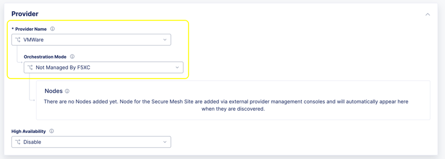
Figure: Select VMware
- Click Add Secure Mesh Site.
Download Node Image
VMWare uses OVA (Open Virtualization Appliance) file to store various files associated with a Virtual Machine (VM). This file is stored in the Open Virtualization Format (OVF) as a TAR archive.
F5 Distributed Cloud packages Customer Edge node software in an OVA template file that lets you add a pre-configured virtual machine to the vCenter Server or ESXi inventory. Using vApps properties of the OVA template, you can configure the Site and specify metadata, such as the node token required to register the CE Site nodes.
-
Navigate to Manage > Site Management > Secure Mesh Sites v2.
-
From the Secure Mesh Sites page, for your site, click ... > Download Image and then save the image locally.
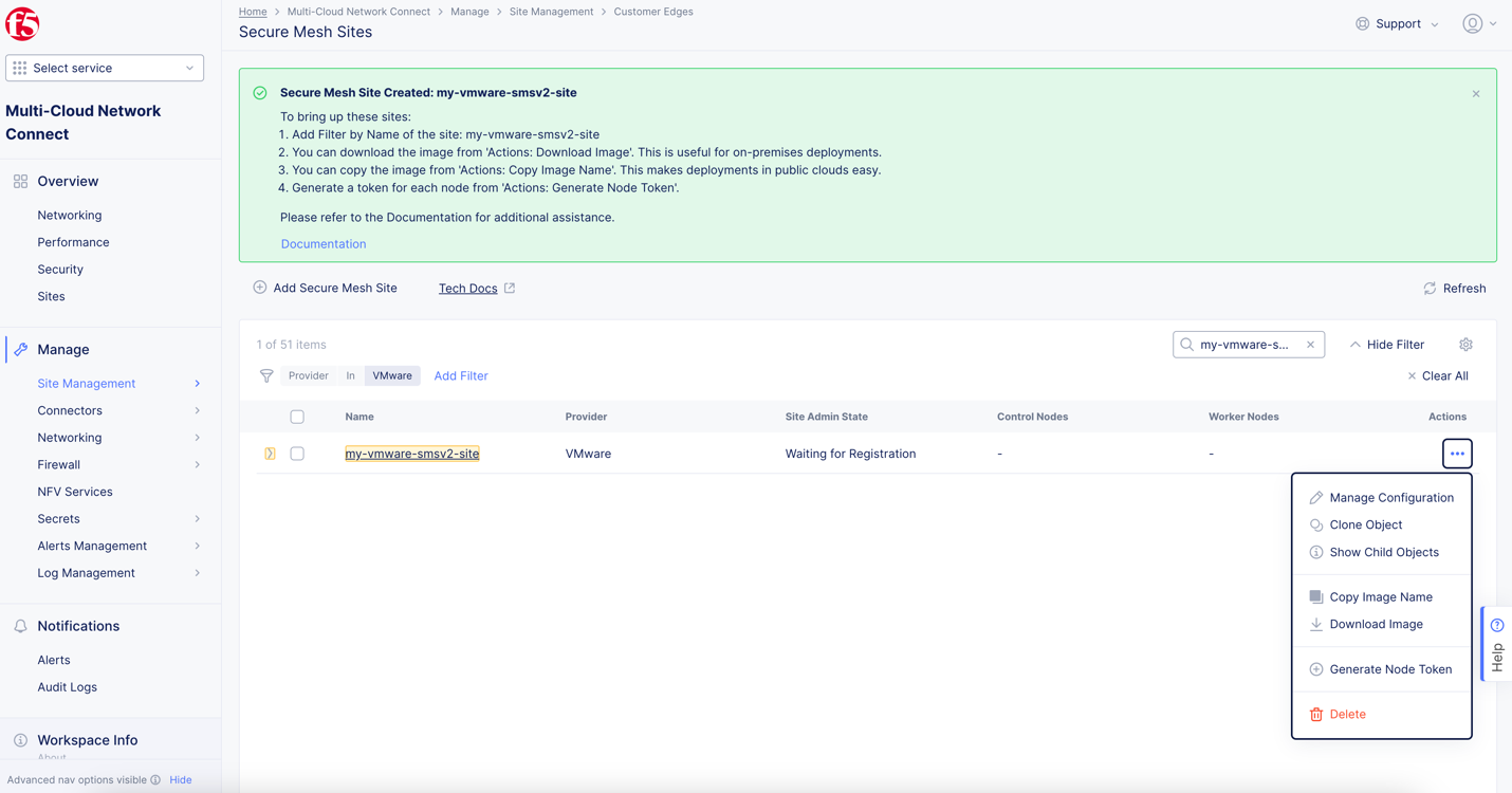
Figure: Download VMware OVA Template
- Ensure that you validate the MD5SUM of the image for an integrity check.
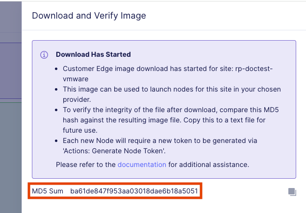
Figure: Hash Integrity Check
- Optionally, to obtain a download link that you can use with CLI utilities, such as curl or wget, click Copy Image Name.
Create Nodes (Virtual Machines)
Follow the steps below to deploy a CE node as a virtual machine (VM) using the OVA software image that was downloaded in the previous section.
Generate Node Token
A node token is required to register a CE Site node to the Distributed Cloud Console.
Important: A new token must be generated for each node that is being created.
-
In Distributed Cloud Console, select the Multi-Cloud Network Connect workspace.
-
Navigate to Manage > Site Management > Secure Mesh Sites v2.
-
For your site, click ... > Generate Node Token.
Figure: Node Token
-
Click Copy.
-
Save the value locally. This token is used later. The token value is hidden for security purposes.
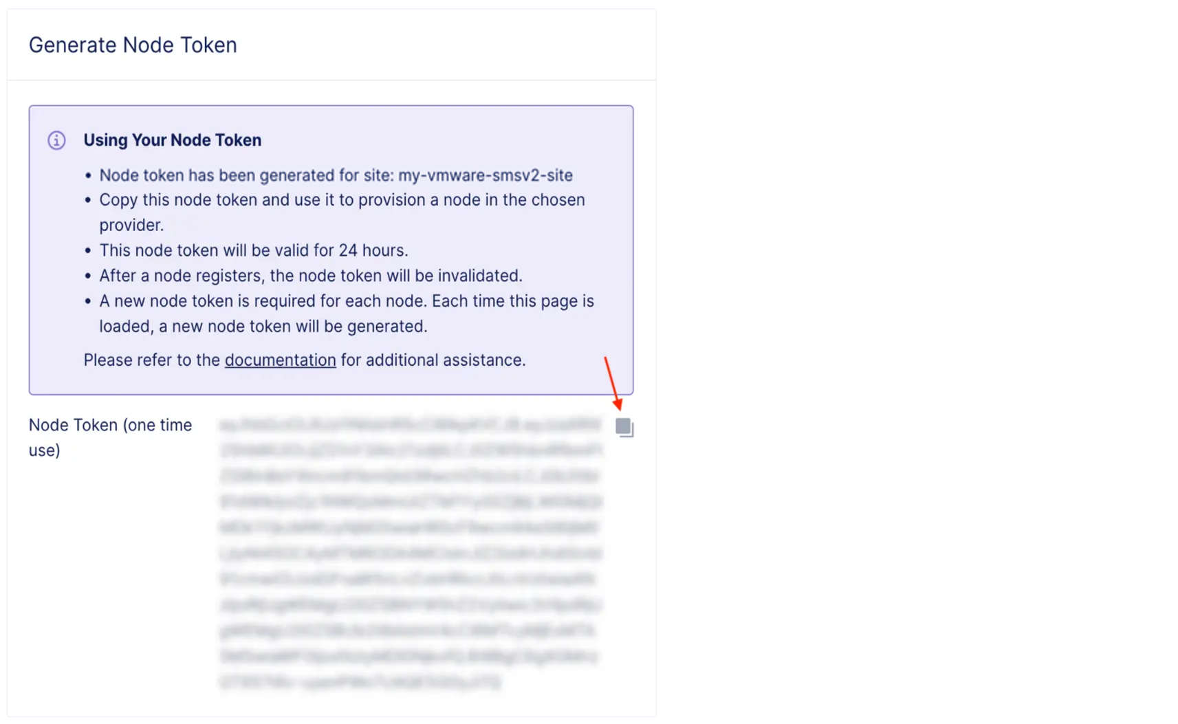
Figure: Node Token
- Click Close.
Create a CE Node (Virtual Machine)
This guide provides two methods to configure a CE node (VM): (1) using the UI and the (2) OVF Tool.
Important: The name of the VM should not have "." in it. For example, the hostname can be node-0 or node0, but it cannot be node.f5.com since it is not supported. Your node VM name must adhere to DNS-1035 label requirements. This means the name must consist of lower case alphanumeric characters or “-“, start with an alphabetic character, and end with an alphanumeric character.
If configuring a multi-node site, each node hostname must be unique.
You must connect the first interface of each CE node (VM) to an IPv4 subnet with connectivity to the Internet.
By default, the CE node uses a proxy hosted by F5 Distributed Cloud that is automatically configured. This can be changed to a customer-owned enterprise proxy.
Create Node Using vCenter UI
Use the instructions below to create CE node (VM) with vSphere Client.
Step 1: Log in to the vSphere Client.
Log in to the vSphere Client. Then click Menu > Hosts and Clusters.
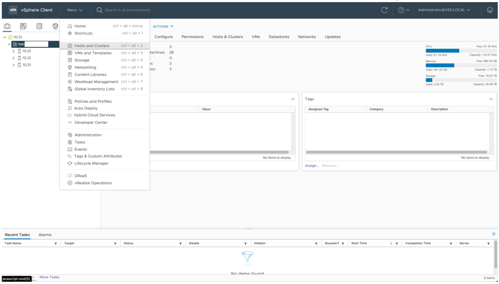
Figure: Log in to vSphere Client
Step 2: Deploy the OVF template.
- Right-click on Data Center and click Deploy OVF Template.
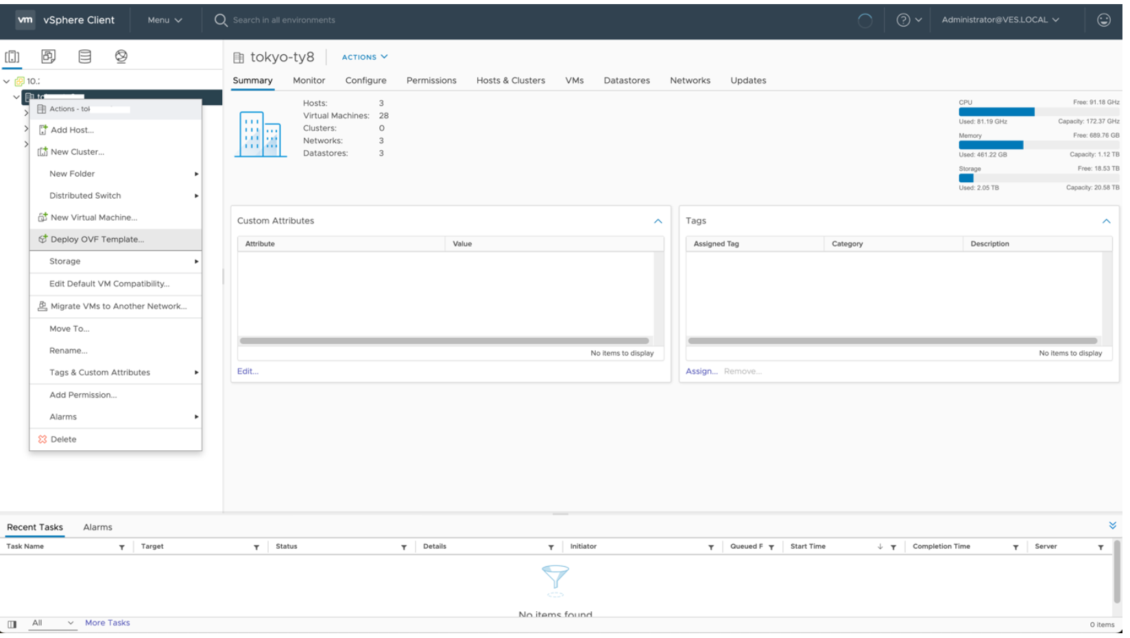
Figure: Deploy the OVF template
- Select the OVF template you downloaded and then click Next.
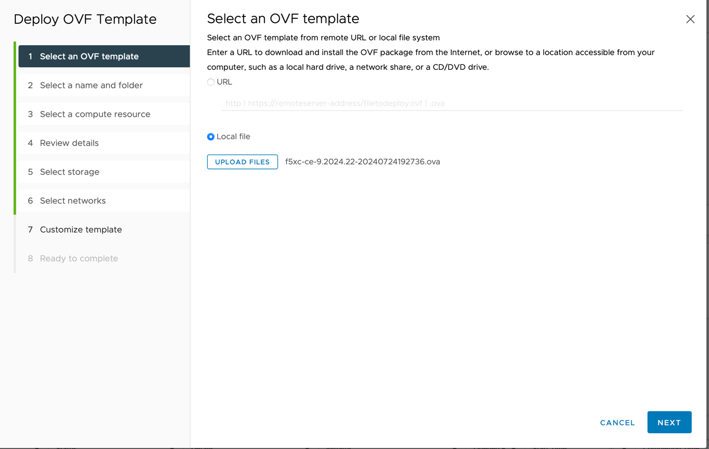
Figure: Select an OVF template
- Enter a unique Virtual machine name and select a folder to store the OVF template. Then click Next.
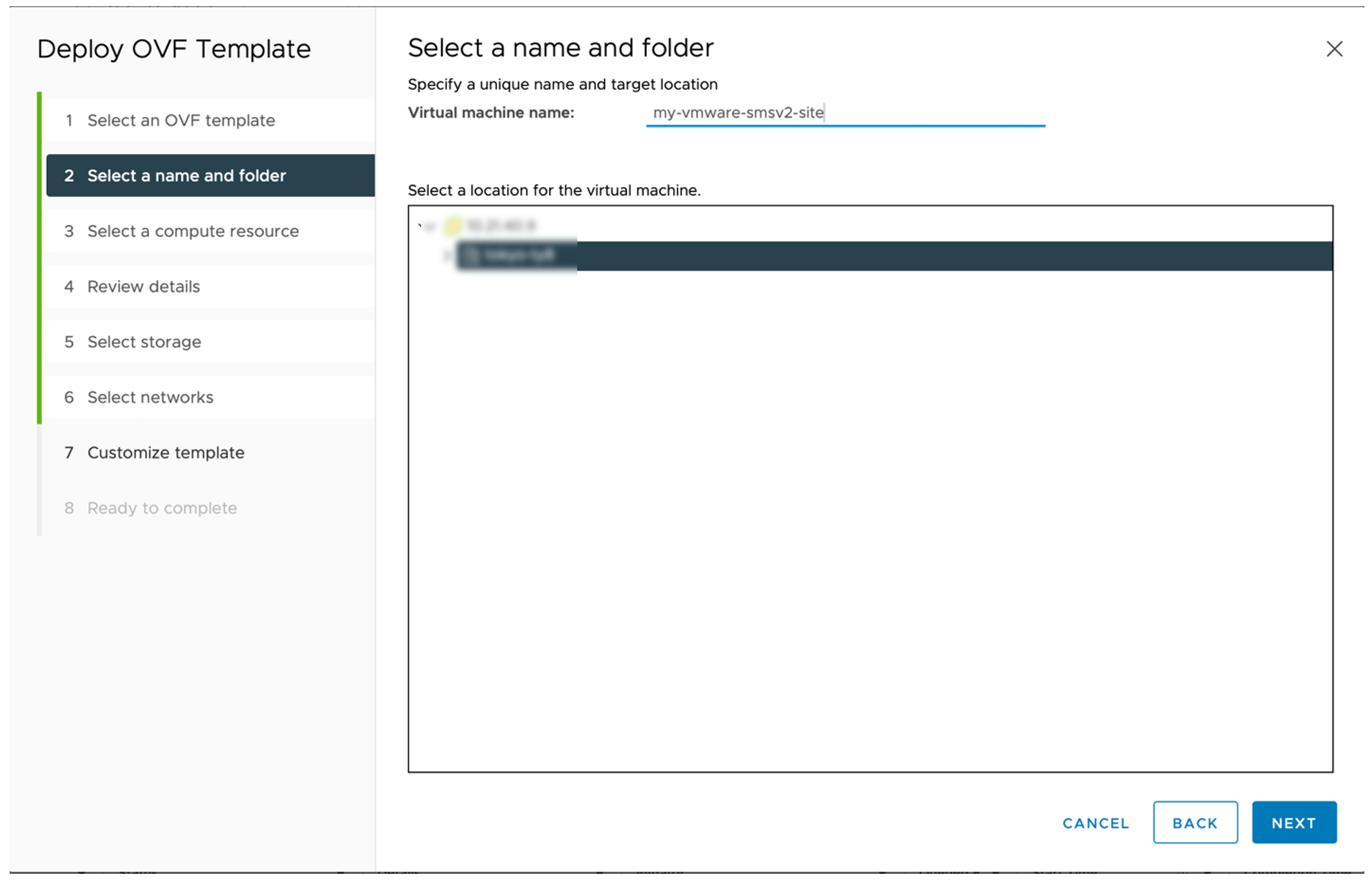
Figure: Select a name and folder
- Select a host to run the template and then click Next.
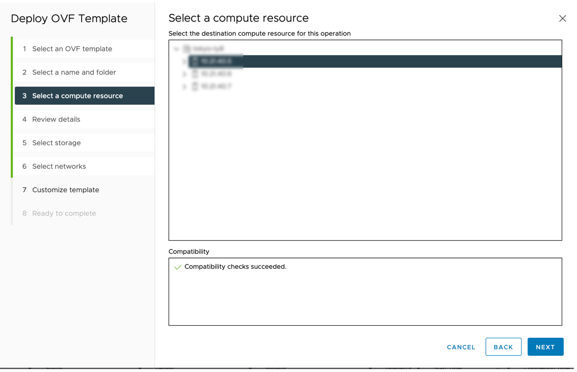
Figure: Select a compute resource
- Review the template details and then click Next.
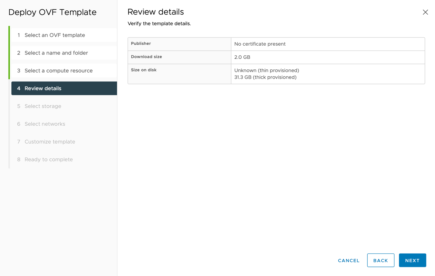
Figure: Review details
- Select where you want to store the files for the deployed template and then click Next.
Important: If you want to encrypt the VM disk, then follow the instructions as described here.
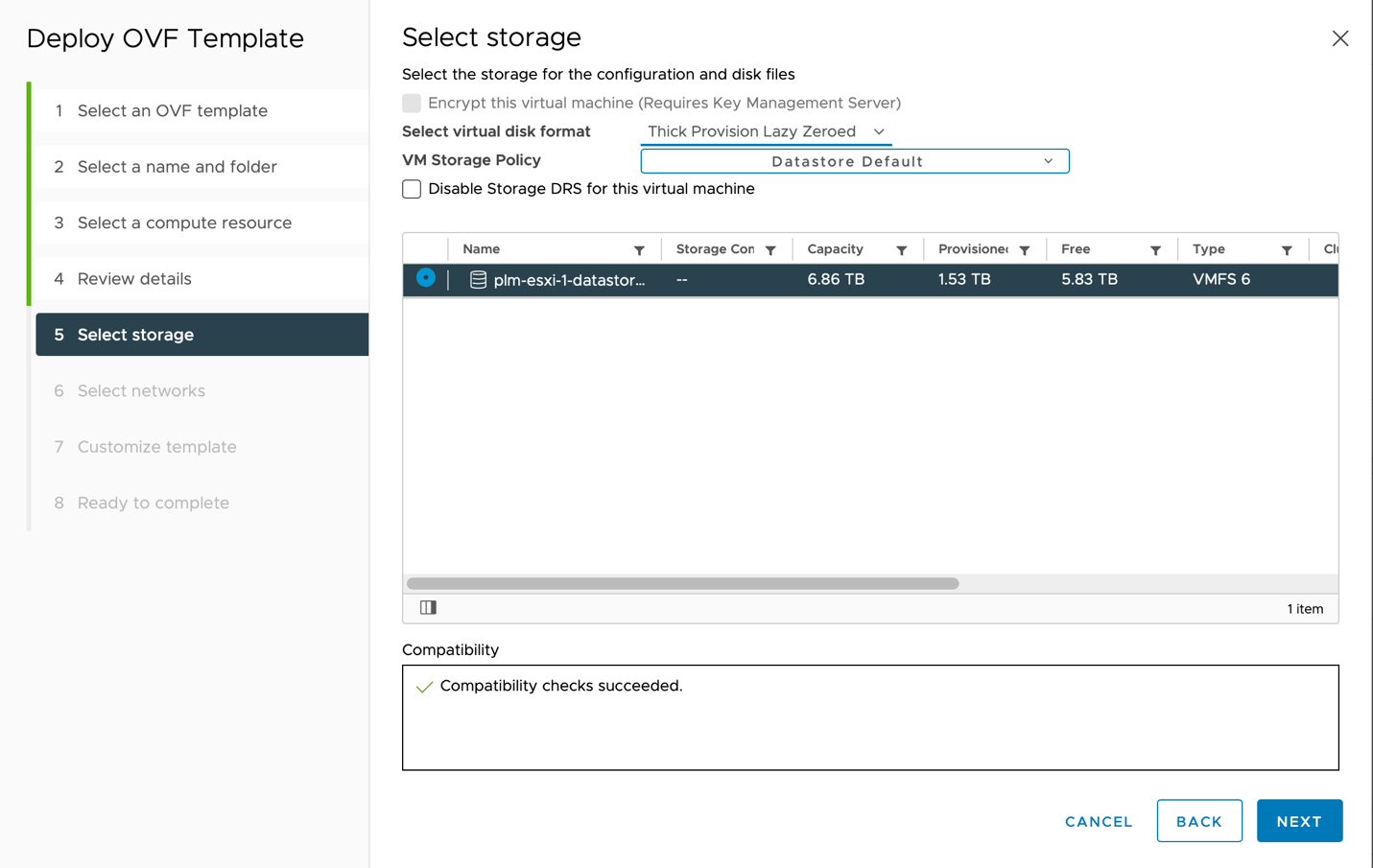
Figure: Select storage
- For the Source Network named OUTSIDE, select a Destination Network. The Destination Network must have an Internet connection. Then click Next. The outside network is the Site Local Outside (SLO) network of the Site.
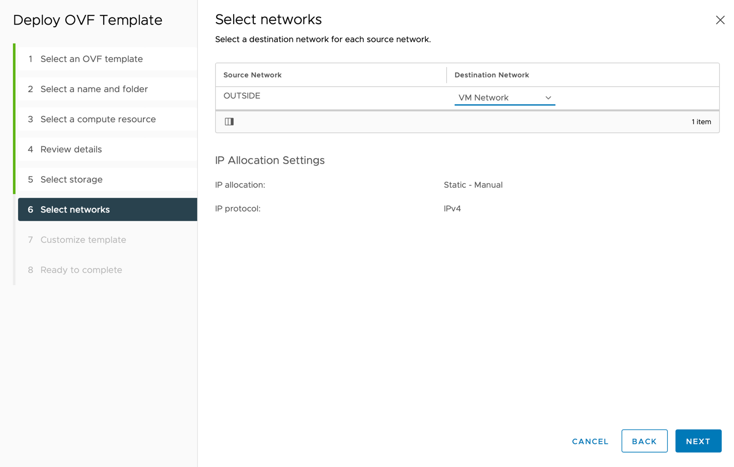
Figure: Select networks
- In the Token field, copy and paste the node token that you saved earlier.
Important: When you create a multi-node Site, make sure to change the Hostname for each node. For example, set hostnames to node-0, node-1 and node-2. Create one node at a time.
-
Keep the default settings for all other configurations.
-
Click Next.
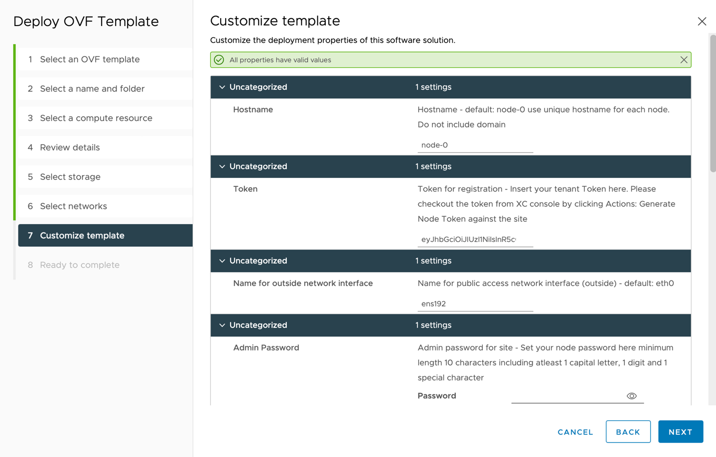
Figure: Customize template
- Click Next and Finish to complete deployment.
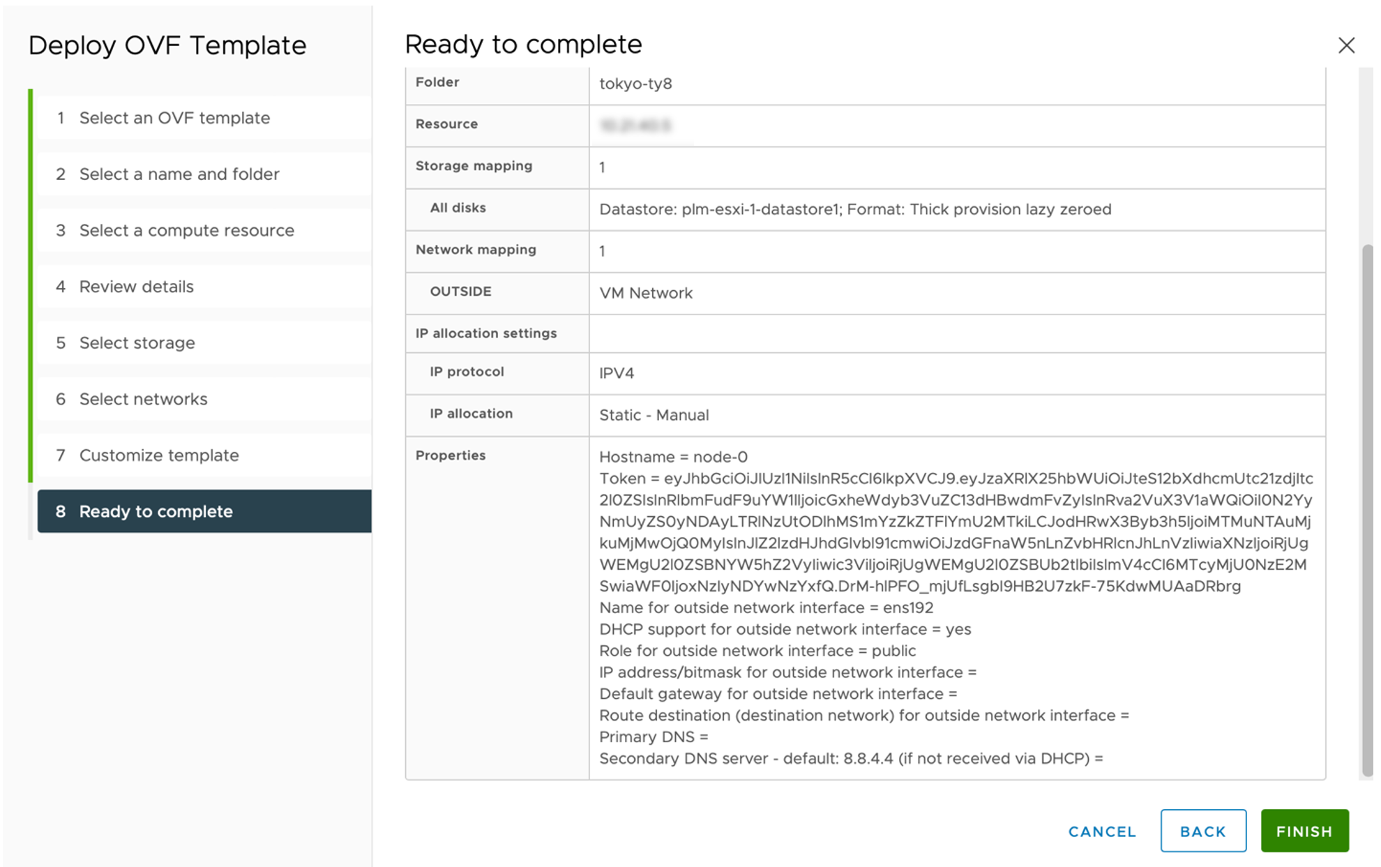
Figure: Ready to complete
Create Node Using OVF Tool
The VMware Open Virtualization Format (OVF) Tool is a command-line (CLI) utility that lets you import and export OVF packages to and from VMware products.
To download the OVF Tool and view the VMware documentation, go to the OVF Tool.
Use the following OVF tool import commands to create a CE node (VM) using the downloaded CE image (OVA):
$ ovftool --noSSLVerify \
--acceptAllEulas \
--allowAllExtraConfig \
--name=<CE_NODE_NAME> \
--datastore=<DATASTORE_NAME> \
--net:"OUTSIDE=<NETWORK_NAME>" \
--vmFolder="<FOLDER_NAME>" \
--prop:guestinfo.ves.token=<TOKEN> \
"<PATH_TO_OVA_FILE>" \
"vi://<USERNAME>:<PASSWORD>@<VCENTER_IP>/<DATACENTER>/host/<CLUSTER>/<HOST_IP>/"
Important: If using a static IP address, add the following OVF properties to the ovftool command:
--prop:guestinfo.interface.0.dhcp=no --prop:guestinfo.interface.0.ip.0.address=<IP_ADDRESS> --prop:guestinfo.interface.0.route.0.gateway=<GATEWAY>
The following table provides information about the parameters above:
| Name | Description |
|---|---|
| CE_NODE_NAME | Name of the CE node. Needs to be unique per node in the CE Site. Should not contain ".". |
| DATASTORE_NAME | Name of the data store/storage on the ESXi host. |
| NETWORK_NAME | Name of the network adapter on the ESXi host with Internet connectivity. |
| FOLDER_NAME | VM and template folder on vSphere. |
| PATH_TO_OVA_FILE | Path to the downloaded CE OVA image. |
| USERNAME | Username of the vSphere client. |
| PASSWORD | Password of the vSphere client user. |
| VCENTER_IP | IP address of the vSphere client. |
| DATACENTER | Name of the data center configured on the vCenter server. |
| CLUSTER | Name of the cluster configured on the vCenter server. |
| HOST_IP | IP address of the ESXi hosts connected on the vCenter server. |
| TOKEN | Generated CE node token from F5 Distributed Cloud Console. Must be unique per CE node (VM). |
| IP_ADDRESS | Static IPv4 address for the CE node (VM) with Internet connectivity to connect to F5 Distributed Cloud (format example: 10.192.145.100/24). |
| GATEWAY | Gateway for the network with Internet connectivity to connect to F5 Distributed Cloud (format example: 10.192.145.1). |
Encrypt VM Disk (Optional)
You can enable disk encryption either during the VM creation or after the VM is created. Follow the steps below for instructions on both procedures.
Enable Disk Encryption During VMware VM Creation
-
To encrypt the disk during VM creation, from the storage selection, select Encrypt this virtual machine (Requires Key Management Server).
-
Select a policy for the VM Storage Policy field.
-
Click Next.
Note: By default, the VM Storage Policy is set to a default data storage policy. Click on it to see a drop-down list with the policies you created.
Enable Disk Encryption for Existing VMware VM using vSphere
Step 1: Power off the VM.
-
Log in using your vSphere client.
-
Right-click on your virtual machine, and then select Power off.
Step 2: Configure storage policies to enable disk encryption.
- Click the Configure tab.
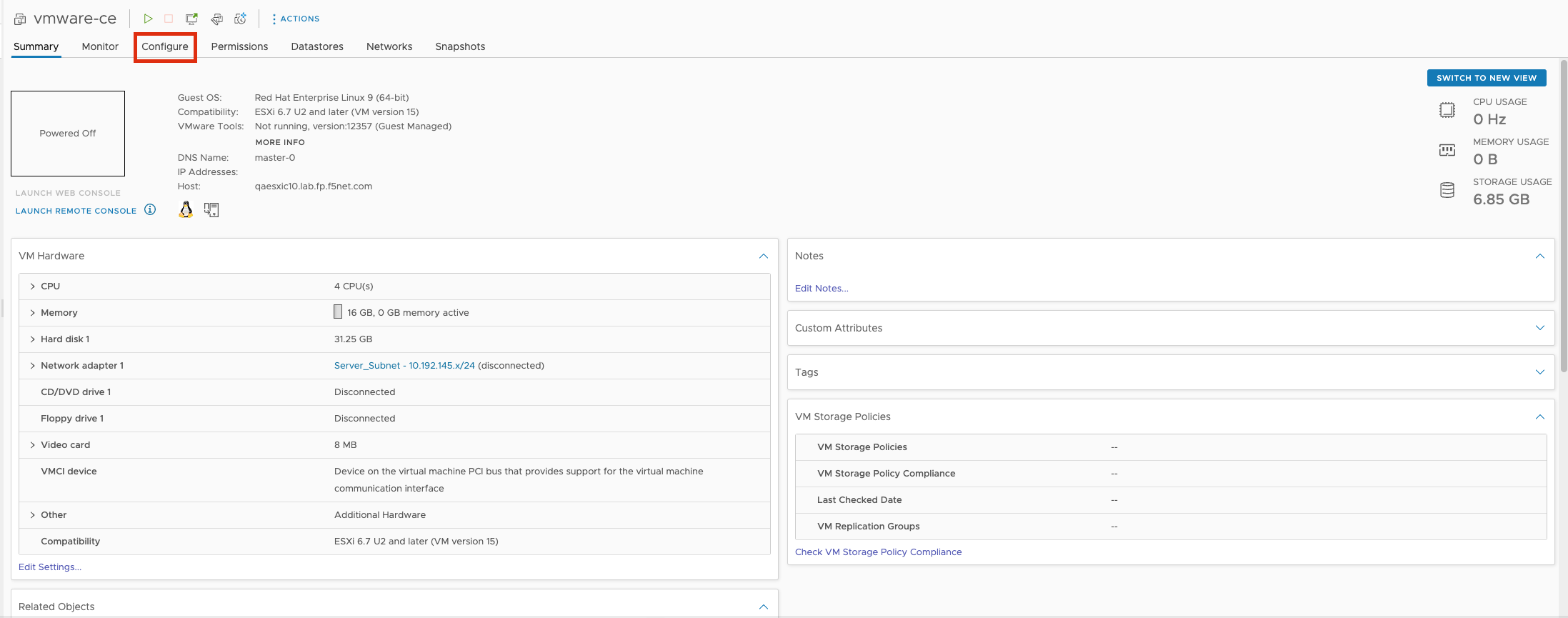
Figure: Open Configure Tag
- Click Policies.
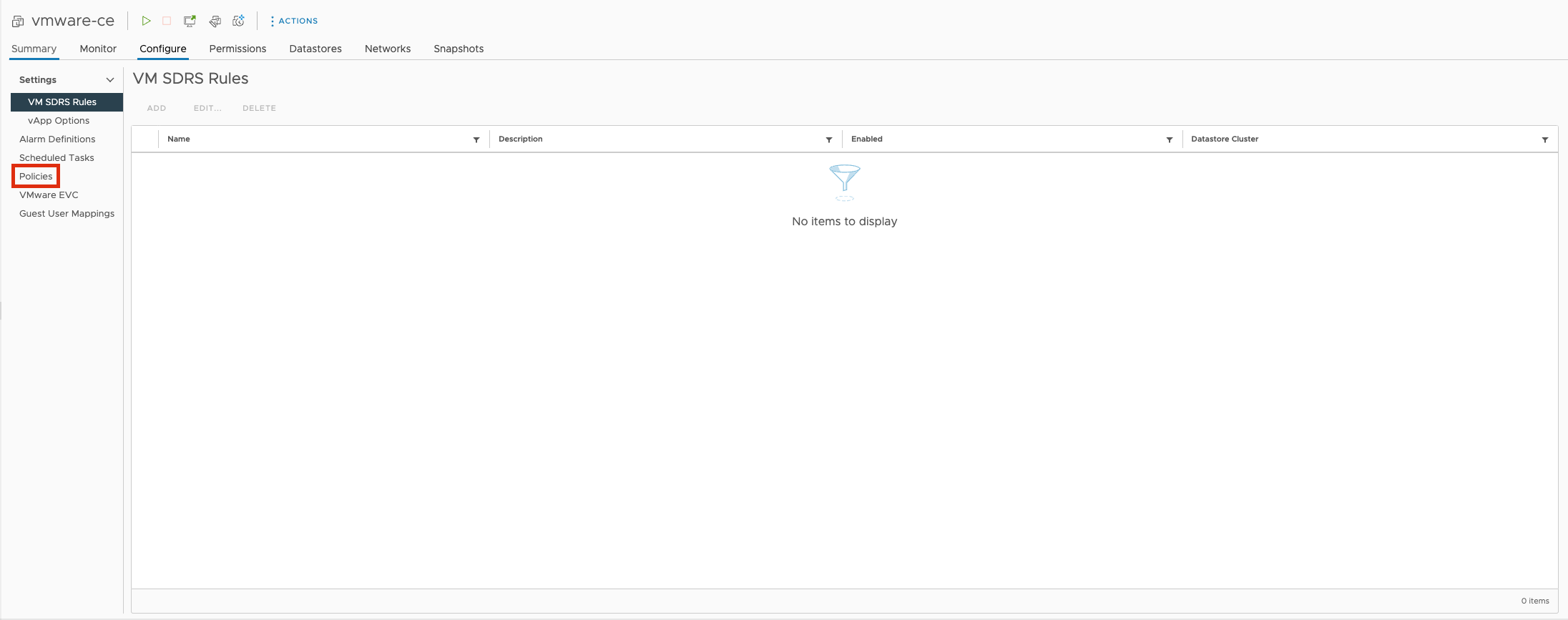
Figure: Open Policies
- Click EDIT VM STORAGE POLICIES.
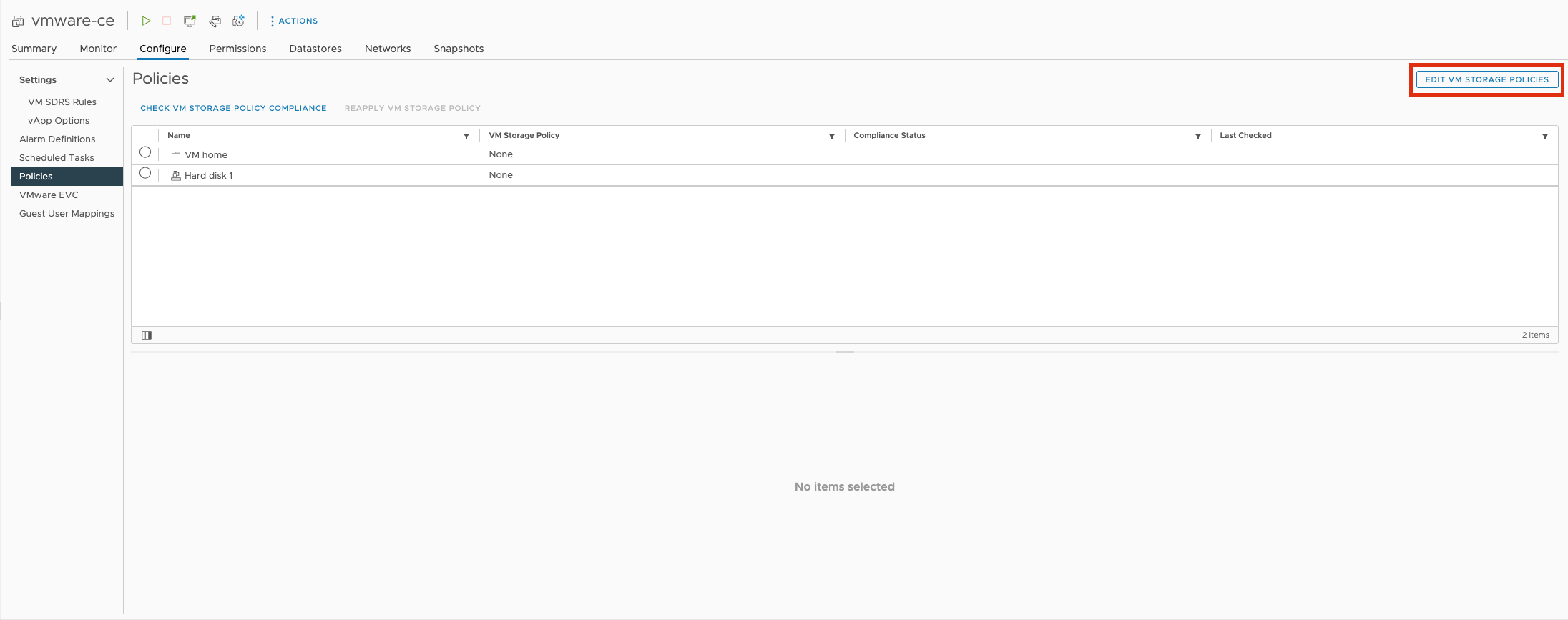
Figure: Edit Storage Policies
- Select your Encryption policy under VM storage policy. The default selection is VM Encryption Policy.
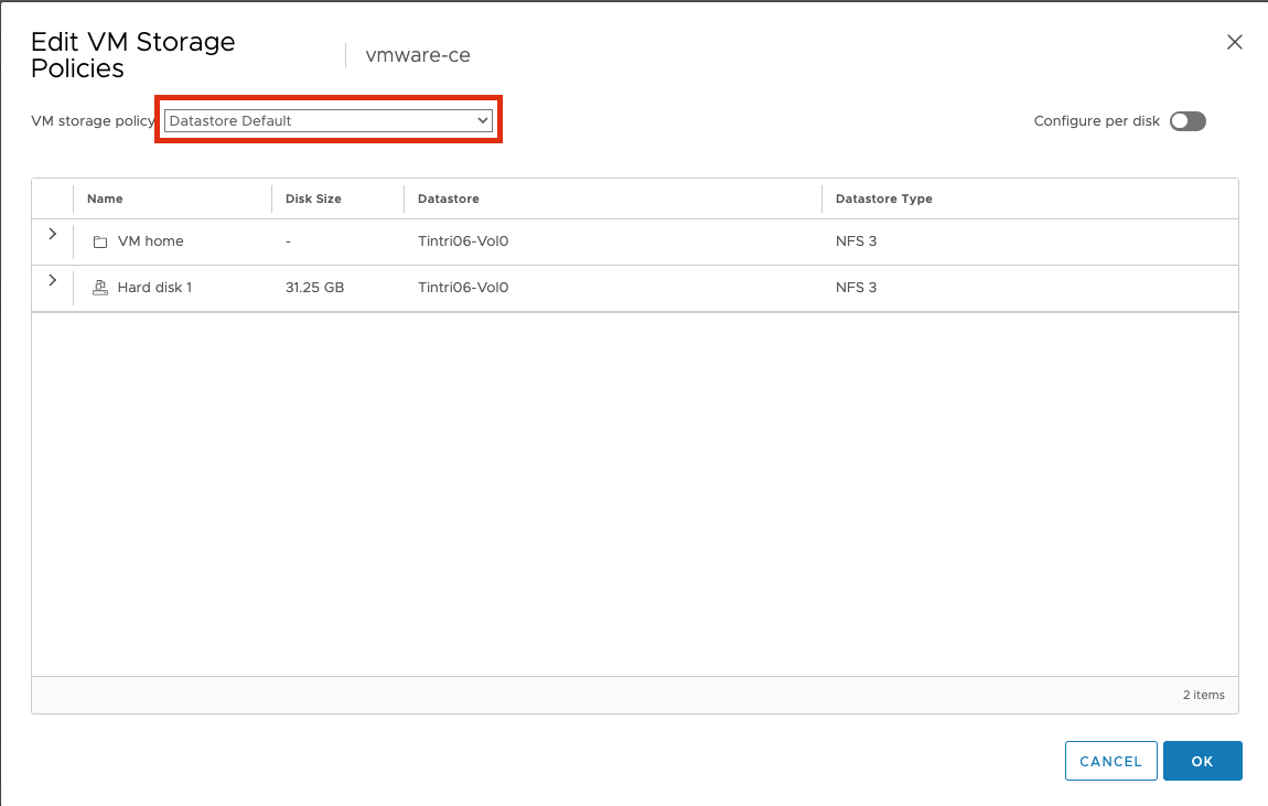
Figure: Select Storage Policies
- Click OK.
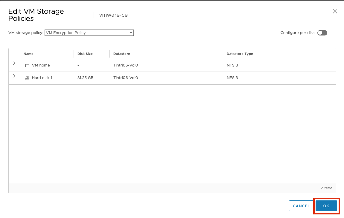
Figure: Click OK
Step 3: Power on the VM.
-
Log in using your vSphere client.
-
Right-click on your virtual machine, and then select Power on.
Verify CE Site Registration
-
In Distributed Cloud Console, navigate to Multi-Cloud Network Connect > Overview > Infrastructure > Sites.
-
Select the site. The Dashboard tab should clearly show that the CE Site has registered successfully with the System Health of 100% as well as Data Plane/Control Plane both being up.
Note: For more information on the site registration process, see the Customer Edge Registration and Upgrade Reference guide.
Manage Network Interfaces (Optional)
After your CE Site registers successfully, you might want to add additional network interfaces to meet your requirements. Ensure that you connect another network interface to the node VM.
Important: Adding or removing network interfaces causes the data plane services on the CE node to restart. Therefore, F5 strongly recommends that you perform this operation during maintenance windows. As data plane services restart, traffic drops are expected, as well as tunnels to F5 Distributed Cloud REs going down.
All CE nodes in a given CE site should have the same number of network interfaces attached. CE nodes with non-homogenous interfaces within a CE Site might cause issues.
Each node in the CE site should have interfaces with the same VRFs assigned. For example: If a CE Site has three nodes, with each node having two interfaces - the first interface on each node is auto-configured to be in the SLO VRF (to connect to F5 Distributed Cloud). If the second interface on node-1 is in the SLI VRF, then the second interface on node-2 and node-3 must also be in the SLI VRF.
When new interfaces are added, they are auto-discovered. You can configure the interface (for example: place the interface in the appropriate VRF) from the CE Site configuration.
The first interface of the CE nodes should not be removed or modified.
After you configure the SLO interface with a static IP address, DHCP will still be displayed in the Console. However, your static IP configuration is well taken into account. Also, remember that you cannot modify SLO parameters once the node is registered and deployed.
Add New Interface
-
Power down all CE nodes (VMs) of the CE Site prior to adding any new interfaces or modifying any existing interfaces.
-
Attach additional network interface(s) to the CE nodes. Make sure to maintain homogeneity. As in, add the same number of interfaces mapped to the same port groups on all CE nodes (VMs).
-
Power on the CE nodes (VMs). The CE Site resource in F5 Distributed Cloud auto-detects changes in the interfaces.
-
In the Multi-Cloud Network Connect workspace, click Manage > Site Management > Secure Mesh Sites v2.
-
For your VMware Site, click ... > Manage Configuration.
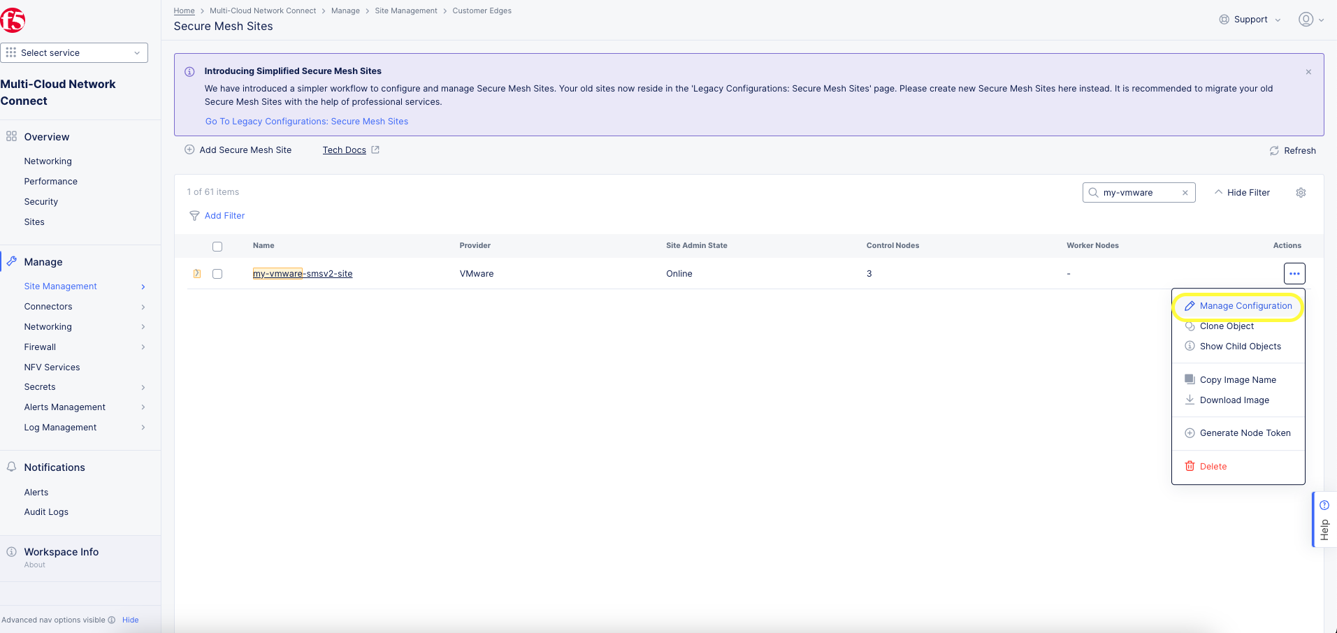
Figure: Manage Site Configuration
- Click Edit Configuration.
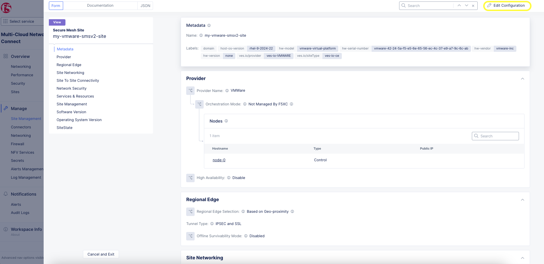
Figure: Edit Configuration
- In the Provider section, click the pencil button to edit the desired node.
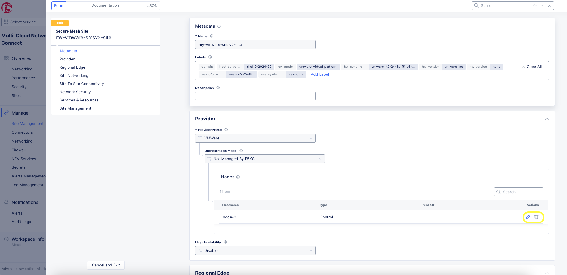
Figure: Edit Node Configuration
- Click the pencil button next to the newly discovered interface. The MAC address is shown in the table for convenience.
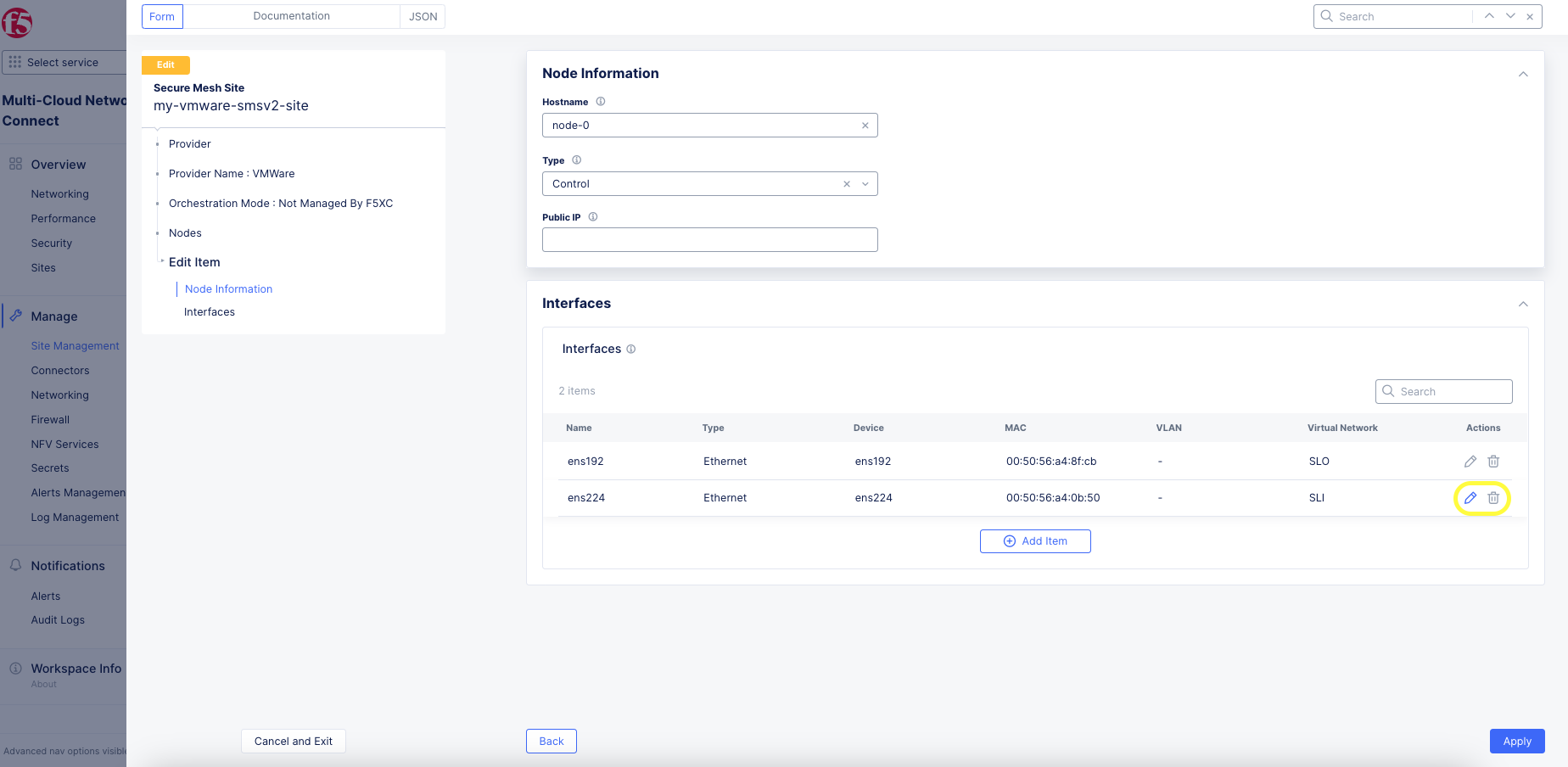
Figure: Add Interface
Note: Interface Name is not a mandatory field but is recommended to be configured.
- Select the un-configured network device that is detected by the node by clicking See Suggestions.
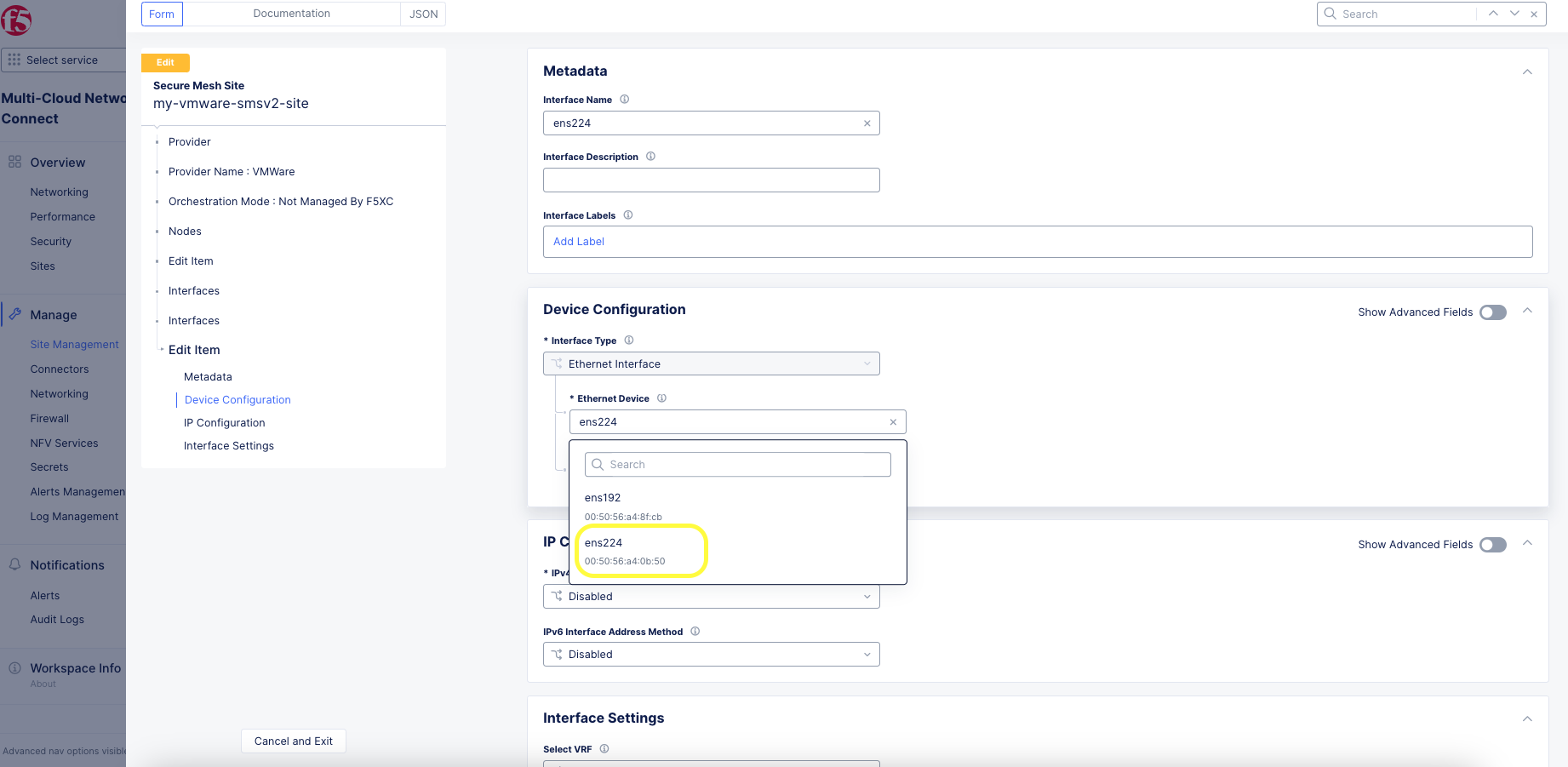
Figure: Ethernet Device
-
From the IPv4 Interface Address Method menu, select the IP address configuration from the following options:
- DHCP Client
- Static IP
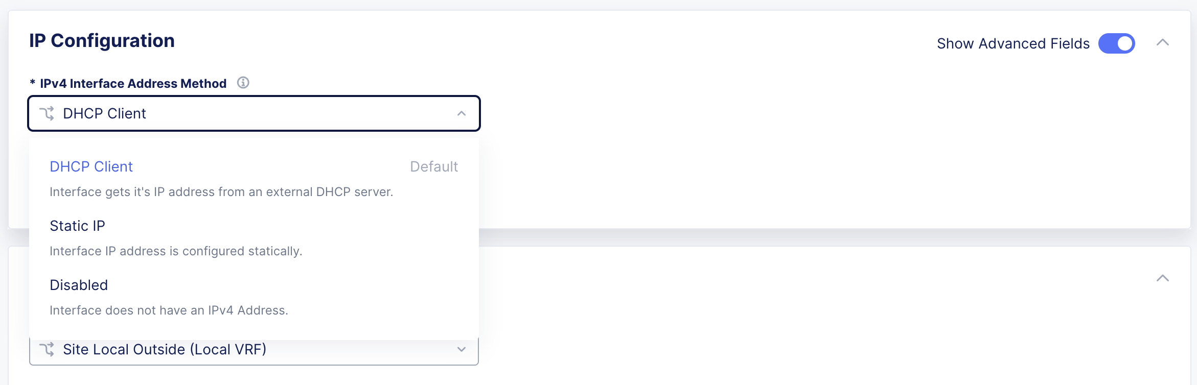
Figure: IP Address Configuration
Important: The IP address for the SLO interface cannot be changed. This change can damage the cluster configuration.
- Assign interface configurations for the Select VRF option to VRF. The default and most common option is Site Local Inside (Local VRF), but can also be assigned to Segment (Global VRF).
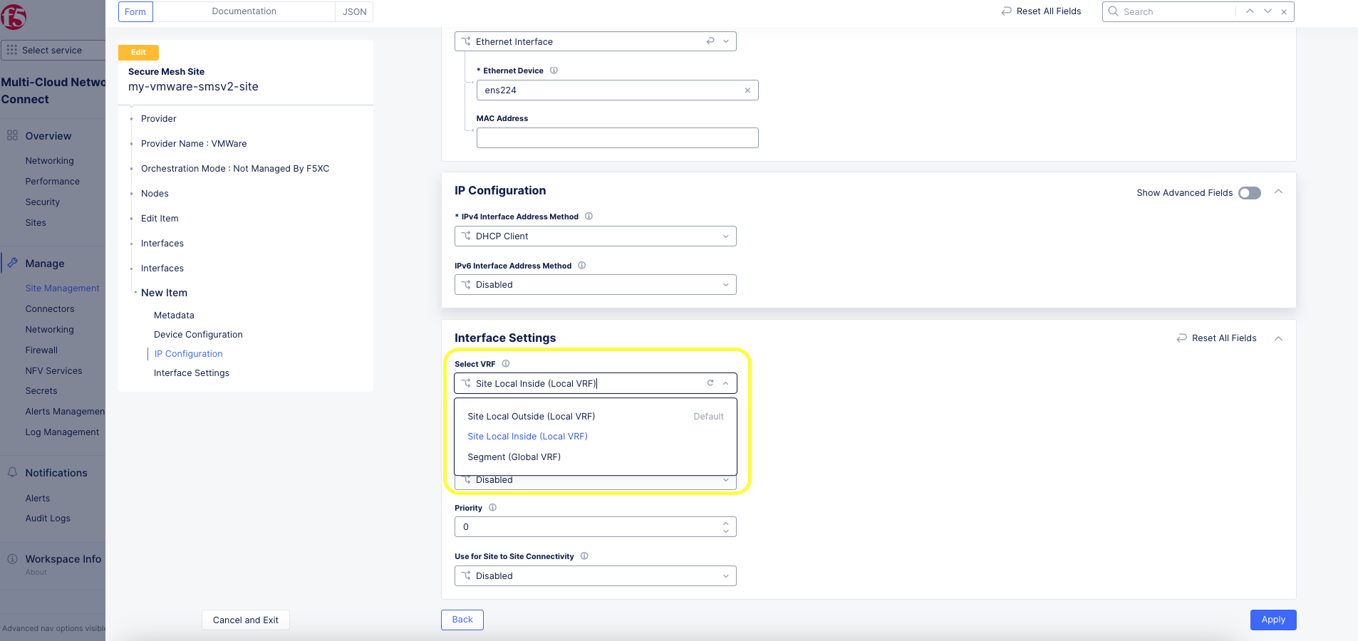
Figure: VRF Configuration
-
Click Apply. Then click Apply again. Then, click Save Secure Mesh Site to complete the Secure Mesh Site configuration.
-
To view the interface details, navigate to the Infrastructure tab in the CE Site dashboard.
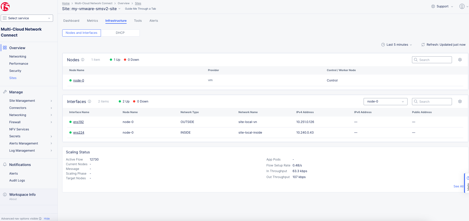
Figure: Interfaces View
Day 2 Operations
- To monitor your Site, see the Monitor Site guide.
- To manage your Site software and OS updates, see the Manage Site guide.
- For troubleshooting issues, see the Troubleshooting Guide for Secure Mesh Site v2 Deployment guide. It provides step-by-step instructions to debug and resolve the issues that may arise due to registration and provisioning errors.
- For the latest on Distributed Cloud Services releases, see Changelogs.
- To view the various types of events generated, see the Events Reference guide.
Related Guides
To create a load balancer on the CE Site, see the HTTP Load Balancer or the TCP Load Balancer guides.
Concepts
On this page:
- Objective
- Planning
- General Prerequisites
- Configuration Overview
- Procedure
- Create Site Object
- Download Node Image
- Create Nodes (Virtual Machines)
- Generate Node Token
- Create a CE Node (Virtual Machine)
- Create Node Using vCenter UI
- Create Node Using OVF Tool
- Encrypt VM Disk (Optional)
- Enable Disk Encryption During VMware VM Creation
- Enable Disk Encryption for Existing VMware VM using vSphere
- Verify CE Site Registration
- Manage Network Interfaces (Optional)
- Add New Interface
- Day 2 Operations
- Related Guides
- Concepts