Deploy Secure Mesh Site v2 on KVM (ClickOps)
Objective
This guide provides instructions on how to create an F5® Distributed Cloud Customer Edge (CE) on KVM using the Secure Mesh Site via F5 Distributed Cloud Console.
Important: This guide does not provide instructions on how to deploy an F5® App Stack Site.
This functionality is in Early Access (EA) and can be used for proof of concept (PoC) or proof of value (PoV) deployments. The functionality will be made Generally Available (GA) over the next couple of releases. Reach out to your account representative for more information.
Planning
Read the following documents before deploying a Secure Mesh Site in any provider environment:
- Understanding F5 Distributed Cloud - Customer Edge (CE)
- CE Datasheet
- CE Supported Platforms Guide
- Customer Edge Site Sizing Reference
- CE Performance Guide: Contact your account representative on CE performance-related information.
- Proxy for CE Registration and Upgrades Reference
- Secure Mesh Sites v2 Frequently Asked Questions
- Customer Edge Registration and Upgrade Reference
- F5 Customer Edge IP Address and Domain Reference for Firewall or Proxy Settings
General Prerequisites
The following general prerequisites apply:
-
A Distributed Cloud Services Account. If you do not have an account, see Getting Started with Console.
-
Resources required per node: Minimum 8 vCPUs, 32 GB RAM, and 80 GB disk storage. For a full listing of the resources required, see the Customer Edge Site Sizing Reference guide. All the nodes in a given CE Site should have the same resources regarding the compute, memory, and disk storage. When deploying in cloud environments, these nodes should use the same instance flavor.
-
Allow traffic from and to the Distributed Cloud public IP addresses to your network and allowlist related domain names. See F5 Customer Edge IP Address and Domain Reference for Firewall or Proxy Settings guide for the list of IP addresses and domain names.
-
F5 assumes that an existing subnet exists with Internet connectivity to attach to the node.
-
The new Secure Mesh Site workflow enables you to have up to eight interfaces. However, these interfaces should be in different subnets. Therefore, make sure you have the required subnets available before creating the CE Site nodes.
-
Internet Control Message Protocol (ICMP) needs to be opened between the CE nodes on the Site Local Outside (SLO) interfaces. This is needed to ensure intra-cluster communication checks.
-
The --cloud-init option was introduced in virt-install version 3.0.0. Ensure you update your system to this version.
Important: After you deploy the CE Site, the IP address for the SLO interface cannot be changed. Also, the MAC address cannot be changed.
Configuration Overview
To create a Secure Mesh Site with KVM, here are the high-level steps:
- Site object configuration: Create and configure a Secure Mesh Site object using F5 Distributed Cloud Console.
- Image management: Download the node image from the configured Secured Mesh Site using the Distributed Cloud Console, and then upload this image to KVM host.
- Node management: Utilize the CE node image and create required CE nodes on KVM. Each CE node is a virtual machine (VM).
- Network interface management: Add additional interfaces on the nodes, if necessary.
Procedure
In this guide, the procedure demonstrates the steps to deploy single-node and multi-node secure mesh sites, with single and dual interfaces.
Create Site Object
-
Create a secure mesh Site object in Distributed Cloud Console. Refer to the Create Secure Mesh Site guide.
-
Set the Provider Name option to KVM.
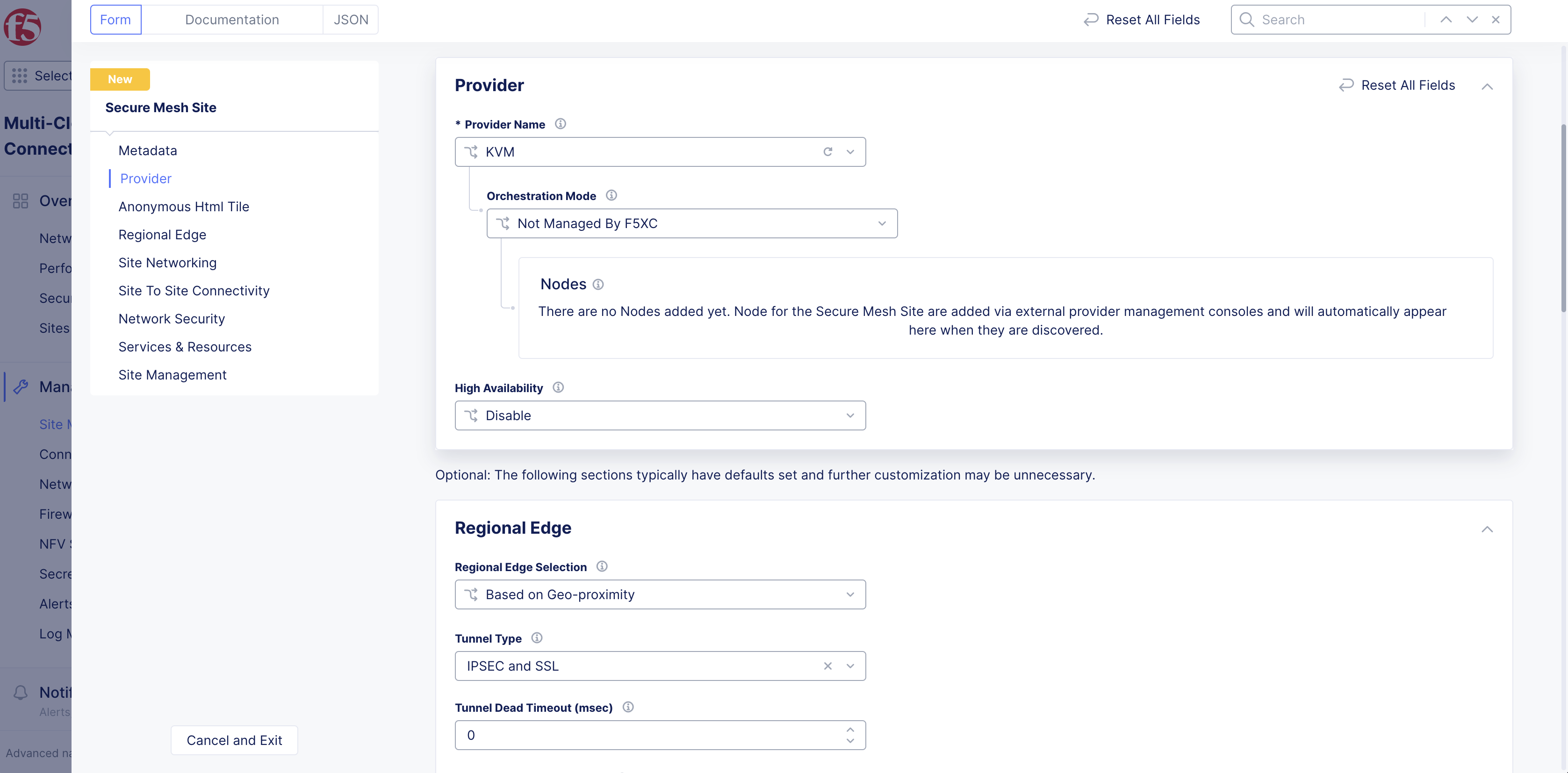
Figure: Provider Type
- For High Availability, choose an option. If it is Disabled, then the CE Site only supports one node. If it is Enabled, the CE Site requires three nodes. Additional nodes can only be added to CE sites when HA is Enabled.
Important: The High Availability mode cannot be changed after the CE Site is created.
-
Leave the other options with their default values. These options have intelligent default values and do not need further configuration. Refer to the Create Secure Mesh Site guide for more information on these options.
-
Click Add Secure Mesh Site.
Connect CE Node Hosted on KVM to F5 Distributed Cloud SaaS
The CE node(s) require(s) connectivity to F5 Distributed Cloud using the public Internet. To facilitate this, the first interface associated with the CE node must be connected to an IPv4 subnet with connectivity to the public Internet. Traffic originating from this interface on a CE node must be allowed to access F5 Distributed Cloud services. Refer to the F5 Customer Edge IP Address and Domain Reference for Firewall or Proxy Settings for more information.
Prepare Node VM User and Metadata
Generate Node Token
A one-time node token is required to register a CE Site node to the Distributed Cloud Console. A new token must be generated for every new node in a CE Site. A token is valid for 24 hours. Make sure that the CE node is deployed soon after the token is generated.
The token is included in the cloud-init information under the Content variable. Also included are two variables commented out: slo_ip and slo_gateway. These variables can be commented out if you are using your own DNS service and not the default DNS service provided by F5.
-
In Distributed Cloud Console, select the Multi-Cloud Network Connect workspace.
-
Navigate to Manage > Site Management > Secure Mesh Sites v2.
-
For your Site, click ... > Generate Node Token.
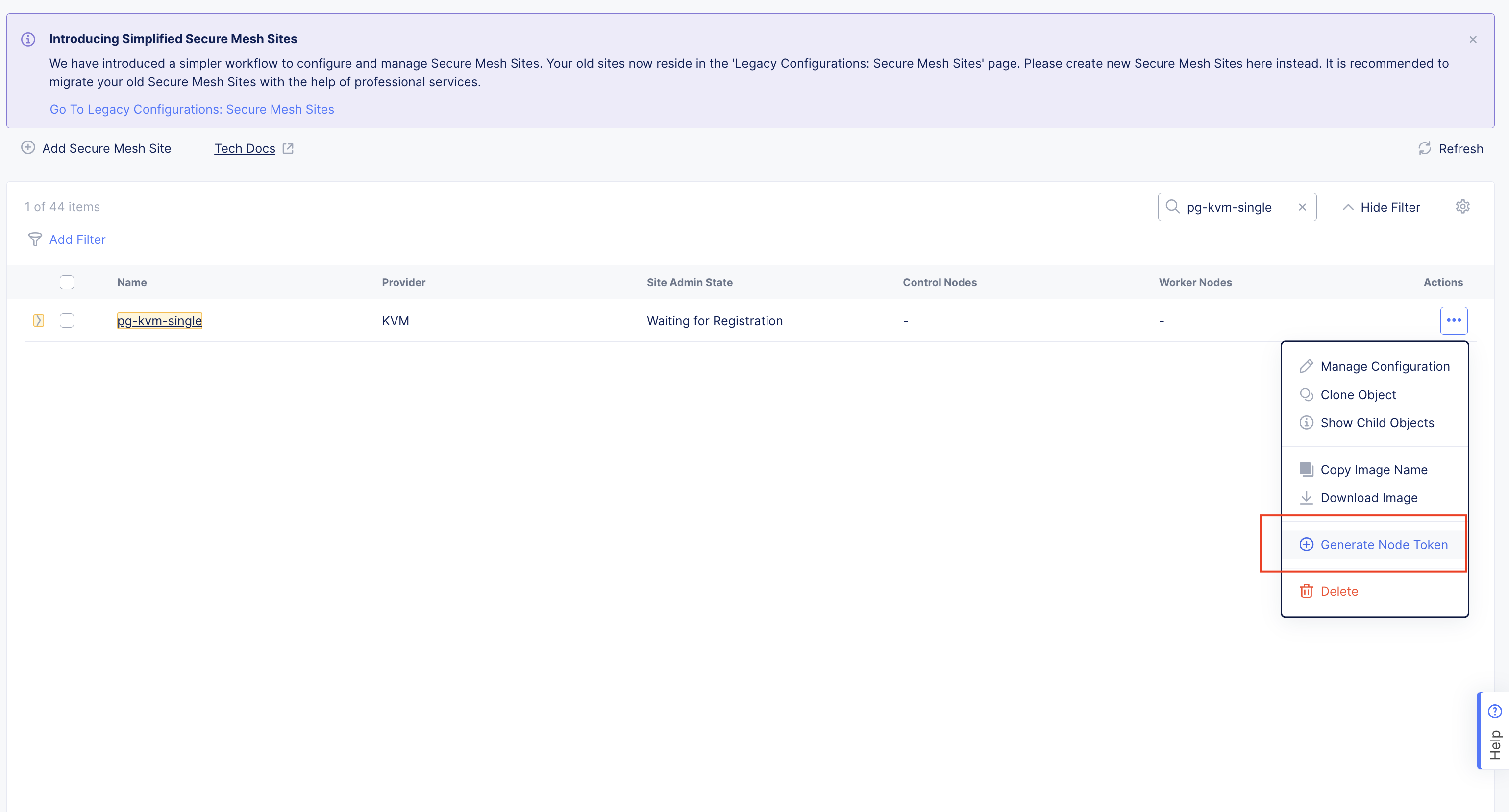
Figure: Node Token
-
Click Copy cloud-init.
-
Save the value locally. This token is used later. The token value is hidden for security purposes.
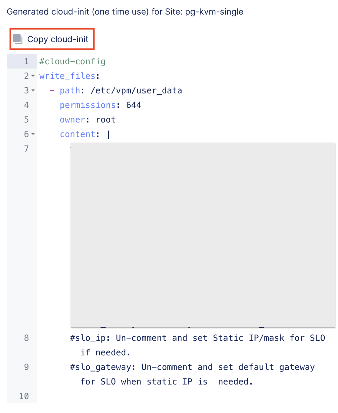
Figure: Copy Node Token
- Click Close.
Additional Parameters
Configure static IP for SLO.
Add lines to user data file.
slo_ip: <IP>/<prefix>
slo_gateway: <GW IP>
slo_dns: <DNS IP>
Full example:
#cloud-config
write_files:
- path: /etc/vpm/user_data
  content: |
    token: <token>
    slo_ip: <IP>/<prefix>
    slo_gateway: <GW IP>
    slo_dns: <DNS IP>
  owner: root
  permissions: '0644'
Configure dedicated proxy server.
- In Console, navigate to your Site and edit the configuration.
- Select the Site Management link from the left menu.
- From the Enterprise Proxy drop-down menu, select Custom Enterprise Proxy.
- Enter your proxy server IP address and port.
- Optionally, configure a username and password.
- Optionally, choose to have your internal proxy server use F5 RE tunnels by choosing Enable from the Use for RE Tunnels drop-down menu.
Important: When Use for RE Tunnels is enabled, the CE Site always establishes a connection to Regional Edges using SSL tunnel encapsulation, even if the Regional Edge tunnel type is set to IPSec and SSL. After the Site comes online, the tunnel type setting in the Regional Edge section is automatically changed to SSL. When RE tunnels are formed via a custom proxy, IPsec cannot be supported because Internet Key Exchange (IKE), which is UDP-based, cannot be routed via a custom proxy. Therefore, the Site setting is changed to disable IPsec and only uses SSL.
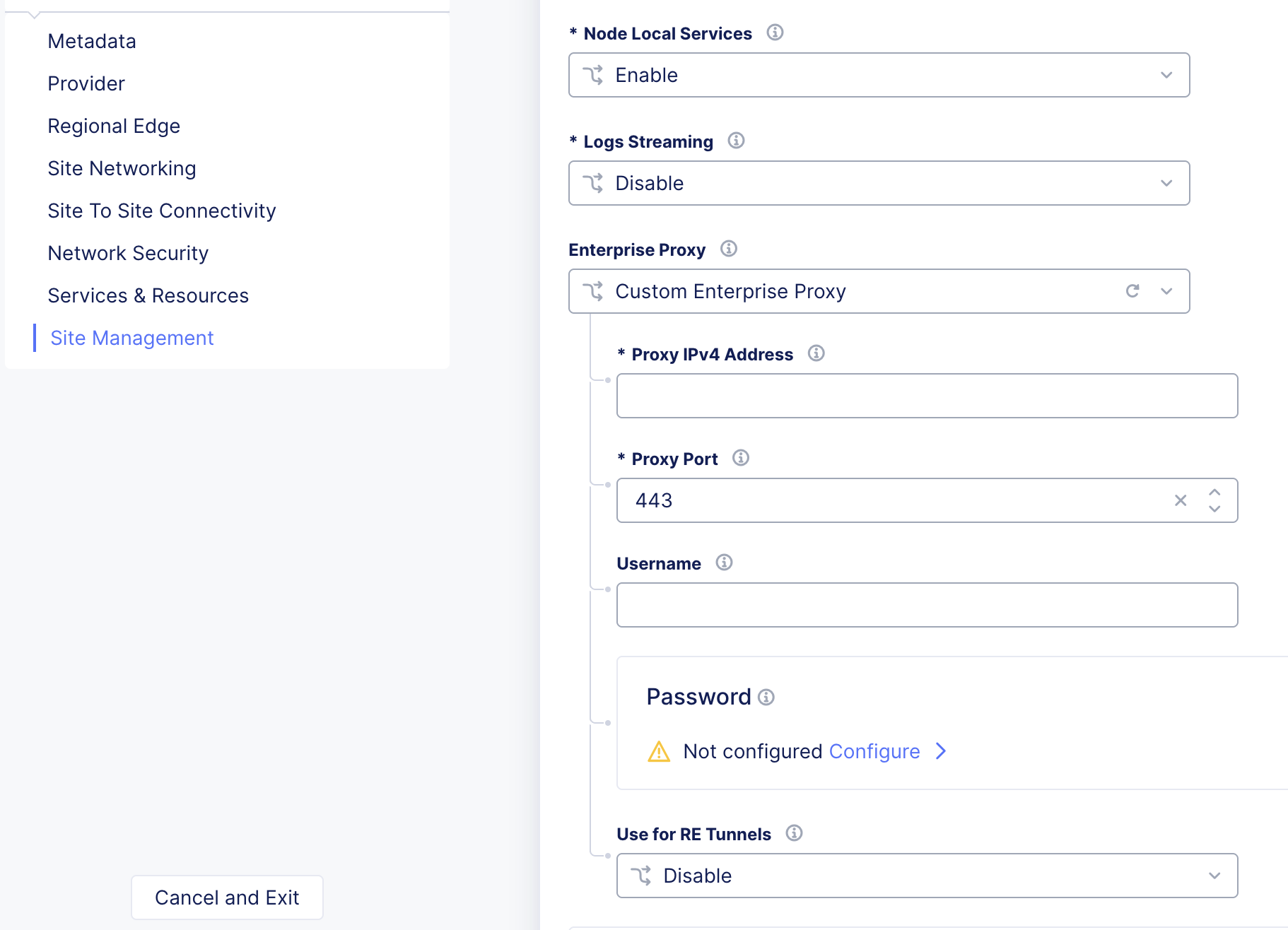
Figure: Configure Custom Proxy Server
- Click Save Secure Mesh Site.
Configure dedicated DNS and NTP.
- In Console, navigate to your Site and edit the configuration.
- Select the Site Management link from the left menu.
- Under the DNS & NTP Servers Settings subsection, perform the following:
- From the DNS Servers menu, select Custom and then click Add Item. Provide the IP address for your DNS server.
- From the NTP Servers menu, select Custom and then click Add Item. Provide the IP address for your NTP server.
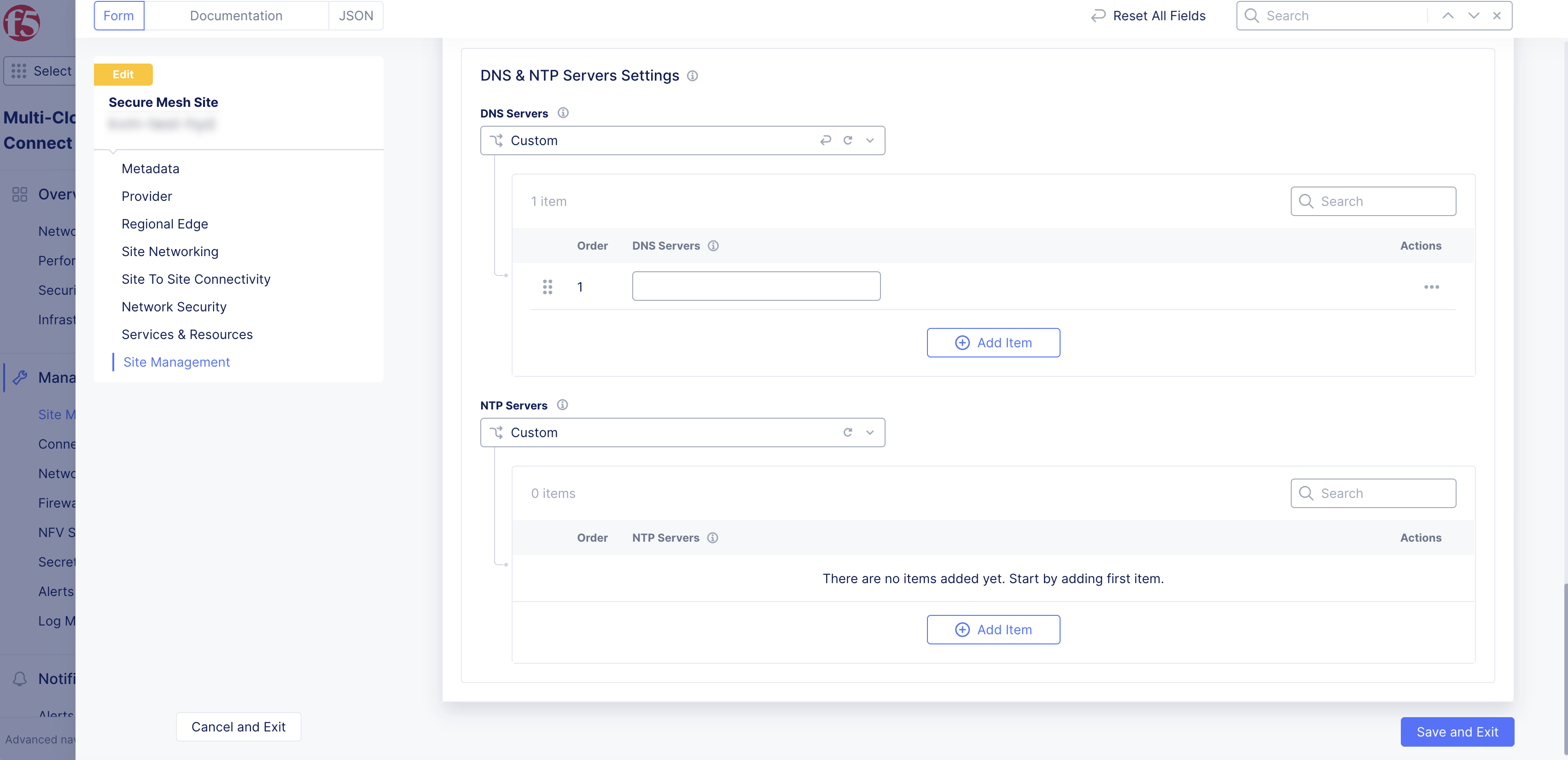
Figure: Configure Custom DNS and NTP Servers
- Click Save Secure Mesh Site.
Download CE Node Image
-
For your Site object, under Actions, click ... > Copy Image Name to receive a download link to use for CLI with the curl or wget commands.
-
To download the image file locally, click Download Image.
Important: The CE node image needs to be downloaded and can be used to deploy multiple nodes.
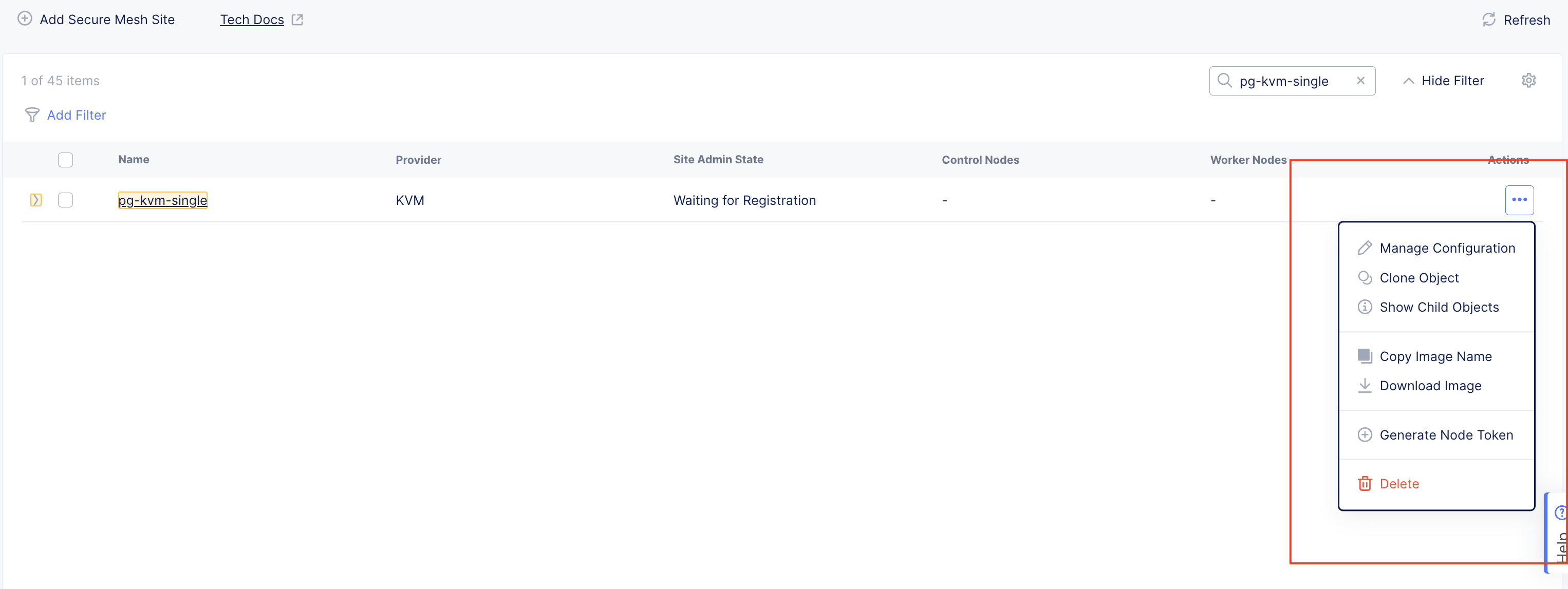
Figure: Copy or Download KVM Image
Create KVM Virtual Machine
Launch the node VM using the user data and qcow2 image files. Ensure the first network provided has Internet connectivity. One interface and two interface examples are provided below.
For a cluster (three-node), three virtual machines need to be created with separate user-data files, where each node must have a new node token generated.
#cloud-config
write_files:
- path: /etc/vpm/user_data
  content: |
    token: <token>
    slo_ip: <IP>/<prefix>
    slo_gateway: <GW IP>
    slo_dns: <DNS IP>
  owner: root
  permissions: '0644'
Important: The name of the VM should not have "." in it. For example, the hostname can be node-0 or node0, but it cannot be node.f5.com since it is not supported. Your node VM name must adhere to DNS-1035 label requirements. This means the name must consist of lower case alphanumeric characters or “-“, start with an alphabetic character, and end with an alphanumeric character.
If configuring a multi-node Site, each node hostname must be unique.
One Interface Configuration
cp f5xc-ce-9.2024.22-20240722122430.qcow2 /var/lib/libvirt/images/kvm-sms-single.qcow2
virt-install --name kvm-sms-single \
        --ram 32000 \
        --vcpus=8 \
        --network network=default,model=virtio  \
        --disk path=/var/lib/libvirt/images/kvm-sms-single.qcow2,bus=virtio,format=qcow2  \
        --cloud-init user-data=user-data.txt \
        --accelerate \
        --os-variant rhl9 \
        --virt-type kvm \
        --noautoconsole \
        --import \
        --graphics vnc
Two Interface Configuration
cp f5xc-ce-9.2024.22-20240722122430.qcow2 /var/lib/libvirt/images/kvm-sms-single.qcow2
virt-install --name kvm-sms-single \
        --ram 32000 \
        --vcpus=8 \
        --network network=default,model=virtio  \
        --network bridge=inside-br,model=virtio \
        --disk path=/var/lib/libvirt/images/kvm-sms-single.qcow2,bus=virtio,format=qcow2  \
        --cloud-init user-data=user-data.txt \
        --accelerate \
        --os-variant rhl9 \
        --virt-type kvm \
        --noautoconsole \
        --import \
        --graphics vnc
- To increase the qcow2 image disk size from a default of 80 GB, you can use the following command:
qemu-img resize /var/lib/libvirt/images/kvm-sms-single.qcow2 100G
- To extend the file system during boot, add the following to the user data (user-data.txt) file:
runcmd:
  - [ sh, -c, test -e /usr/bin/fsextend  && /usr/bin/fsextend || true ]
Note: After the VM boots up, there is no need to log in through Console to provide any additional commands. The node is identified and associated with the CE Site using the token. To view the deployment progress, navigate to your Site and confirm System Health is 100%. It may take some time for the status to update from Waiting for Registration to Provisioning.
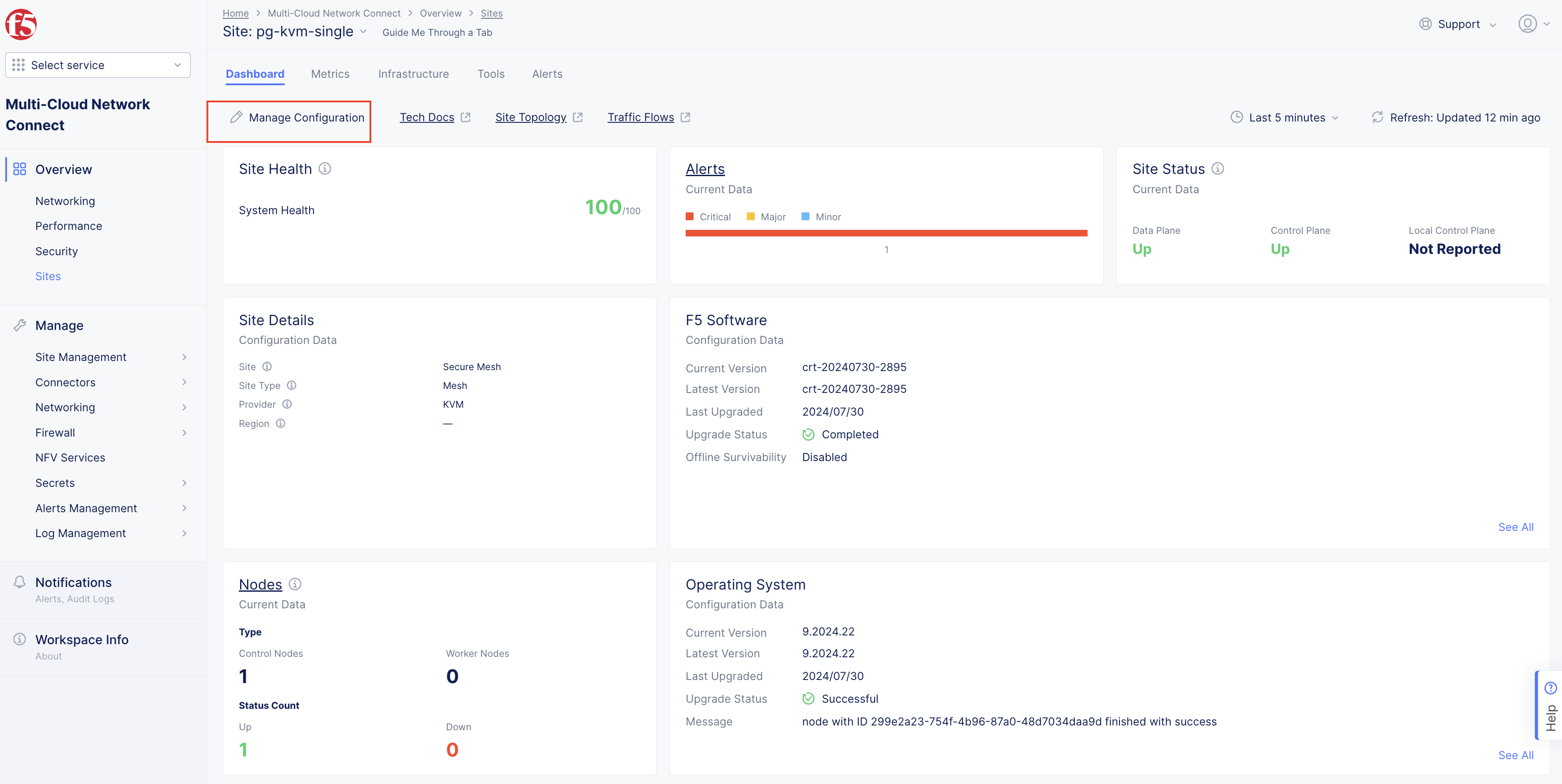
Figure: Site System Health
Verify CE Site Registration
-
In Distributed Cloud Console, navigate to Multi-Cloud Network Connect > Overview > Infrastructure > Sites.
-
Select the Site. The Dashboard tab should clearly show that the CE Site has registered successfully with the System Health of 100% as well as Data Plane/Control Plane both being up.
Note: For more information on the Site registration process, see the Customer Edge Registration and Upgrade Reference guide.
Manage Network Interfaces (Optional)
After your CE Site registers successfully, you might want to add additional network interfaces to meet your requirements. Ensure that you connect another network interface to the node VM.
Important: Adding or removing network interfaces causes the data plane services on the CE node to restart. Therefore, F5 strongly recommends that you perform this operation during maintenance windows. As data plane services restart, traffic drops are expected, as well as tunnels to F5 Distributed Cloud REs going down.
All CE nodes in a given CE Site should have the same number of network interfaces attached. CE nodes with non-homogenous interfaces within a CE Site might cause issues.
Each node in the CE Site should have interfaces with the same VRFs assigned. For example: If a CE Site has three nodes, with each node having two interfaces - the first interface on each node is auto-configured to be in the SLO VRF (to connect to F5 Distributed Cloud). If the second interface on node-1 is in the SLI VRF, then the second interface on node-2 and node-3 must also be in the SLI VRF.
When new interfaces are added, they are auto-discovered. You can configure the interface (for example: place the interface in the appropriate VRF) from the CE Site configuration.
The first interface of the CE nodes should not be removed or modified.
After you configure the SLO interface with a static IP address, DHCP will still be displayed in the Console. However, your static IP configuration is well taken into account. Also, remember that you cannot modify SLO parameters once the node is registered and deployed.
Add New Interface
-
Power down all CE nodes (VMs) of the CE Site prior to adding any new interfaces or modifying any existing interfaces.
-
Attach additional network interface(s) to the CE nodes. Make sure to maintain homogeneity. As in, add the same number of interfaces mapped to the same port groups on all CE nodes (VMs).
-
Power on the CE nodes (VMs). The CE Site resource F5 Distributed Cloud Console auto-detects changes in the interfaces.
Modify Interface Attributes
Step 1: Modify interface.
-
Power down all CE nodes (VMs) of the CE Site prior to modifying any existing interfaces.
-
In the Multi-Cloud Network Connect workspace, click Manage > Site Management > Secure Mesh Sites v2.
-
For your Site, click ... > Manage Configuration.
-
Click Edit Configuration.
-
In the Provider section, click the pencil button to edit the desired node.
-
Click the pencil button next to the newly discovered interface. The MAC address is shown in the table for convenience.
Note: Interface Name is not a mandatory field but is recommended to be configured.
-
Select the un-configured network device that is detected by the node by clicking See Suggestions.
-
From the IPv4 Interface Address Method menu, select the IP address configuration from the following options:
- DHCP Client
- Static IP
Important: The IP address for the SLO interface cannot be changed. This change can damage the cluster configuration.
-
Assign interface configurations for the Select VRF option to VRF. The default and most common option is Site Local Inside (Local VRF), but can also be assigned to Segment (Global VRF).
-
Click Apply. Then, click Apply again.
Step 2: Verify changes in Distributed Cloud Console.
-
Click Save Secure Mesh Site to complete the Secure Mesh Site configuration.
-
To view the interface details, navigate to the Infrastructure tab in the CE Site dashboard.
Day 2 Operations
- To monitor your Site, see the Monitor Site guide.
- To manage your Site software and OS updates, see the Manage Site guide.
- For troubleshooting issues, see the Troubleshooting Guide for Secure Mesh Site v2 Deployment guide. It provides step-by-step instructions to debug and resolve the issues that may arise due to registration and provisioning errors.
- For the latest on Distributed Cloud Services releases, see Changelogs.
- To view the various types of events generated, see the Events Reference guide.
Related Guides
To create a load balancer on the CE Site, see the HTTP Load Balancer or the TCP Load Balancer guides.
Concepts
On this page:
- Objective
- Planning
- General Prerequisites
- Configuration Overview
- Procedure
- Create Site Object
- Connect CE Node Hosted on KVM to F5 Distributed Cloud SaaS
- Prepare Node VM User and Metadata
- Generate Node Token
- Additional Parameters
- Download CE Node Image
- Create KVM Virtual Machine
- Verify CE Site Registration
- Manage Network Interfaces (Optional)
- Add New Interface
- Modify Interface Attributes
- Day 2 Operations
- Related Guides
- Concepts