Deploy Site in Azure (ClickOps)
Objective
Important: This is a legacy workflow for deploying Customer Edge (CE) sites and is not recommended to use. A new workflow for deploying Customer Edge (CE) sites has been introduced and is now Generally Available (GA). F5 recommends you use the new Secure Mesh Site (v2) workflow for all your Customer Edge deployments. You can find this workflow here.
This guide will show you how to create a single-node mesh site with dual interfaces (ingress/egress gateway). However, this guide will also incorporate the differences that you can successfully deploy an Azure CE Site using both Mesh or App Stack and in any supported combination of nodes and interfaces.
Site Types and Scenarios
The scenarios below in the table have been tested successfully. The Network Address Translation Gateway (NAT GW) device in Table 1 references the Azure NAT Gateway. However, technically this should also work with third-party firewalls.
Note: In the
Number of Nodescolumn,1/3indicates 1 or 3 nodes.IGWreferences Internet Gateway.
| Provider | Site Type | Number of Nodes | Gateway Type | Interfaces | Scenario |
|---|---|---|---|---|---|
| Azure | Mesh | 1/3 | Ingress/Egress | 2 | Behind IGW |
| Azure | Mesh | 1/3 | Ingress | 1 | Behind IGW |
| Azure | App Stack | 1/3 | - | 1 | Behind IGW |
| Azure | Mesh | 1/3 | Ingress/Egress | 2 | Behind NAT GW |
| Azure | Mesh | 1/3 | Ingress | 1 | Behind NAT GW |
| Azure | App Stack | 1/3 | - | 1 | Behind NAT GW |
Considerations for Sites Behind NAT Gateway
In a regular deployment, each CE node has a Public IP associated with the SLO interface and the Azure system routes, direct the outgoing traffic via the Internet Gateway using the Public IP as the NAT IP.
But for scenarios where there is a requirement to have the CE site deployed without a Public IP address, you can place the CE behind a NAT Gateway. This can be the Azure NAT gateway or any third-party instance, like a firewall used as a NAT gateway.
For scenarios where there is a requirement to have the CE site deployed without a public IP address, you can place the CE behind a NAT Gateway.
If you are deploying a site in this scenario, there are a few differences to note:
-
There is no public IP association with the CE(s).
-
You must ensure the CE can get to the Internet through its SLO interface.
-
From the Azure side, ensure that the routing table from the SLO subnet has a default route 0.0.0.0/0 that points to the NAT Gateway.
-
The NAT Gateway is a zonal object. In other words, it belongs to one availability zone. Therefore, in the case of a three-node CE cluster, you might want to deploy additional NAT Gateways for high availability.
Prerequisites
The following prerequisites apply:
-
A Distributed Cloud Services Account. If you do not have an account, see Getting Started with Console.
-
An account with Microsoft Azure. See Azure VNet Policies and Permissions Reference guide for permissions needed to deploy site. To create a cloud credentials object, see Cloud Credentials.
-
Resources required per node: Minimum 8 vCPUs, 32 GB RAM, and 80 GB disk storage. However, to deploy an F5® Distributed Cloud App Stack Site, 100 GB is the recommended minimum amount of storage. For a full listing of the resources required, see the Customer Edge Site Sizing Reference guide. All the nodes in a given CE Site should have the same resources regarding the compute, memory, and disk storage. When deploying in cloud environments, these nodes should use the same instance flavor.
-
Allow traffic from and to the Distributed Cloud public IP addresses to your network and allowlist related domain names. See F5 Customer Edge IP Address and Domain Reference for Firewall or Proxy Settings guide for the list of IP addresses and domain names.
-
F5 assumes that the resource group exists with a virtual network, including a minimum of two subnets: one for the Site Local Outside (SLO) and one for the Site Local Inside (SLI). The CE generally references the SLO interface as
eth0and the SLI interface aseth1. -
For a single-NIC deployment (ingress gateway/Mesh or App Stack), only a single subnet (SLO) is required.
-
Internet Control Message Protocol (ICMP) needs to be opened between the CE nodes on the Site Local Outside (SLO) interfaces. This is needed to ensure intra-cluster communication checks.
Important: After you deploy the CE Site, the IP address for the SLO interface cannot be changed. Also, the MAC address cannot be changed.
Procedure
This procedure provides instructions for creating a Secure Mesh Site with two interfaces (ingress/egress) on an Azure VNet using Azure portal. Most of the objects and configurations are the same for single-node and multi-node sites.
The steps differ only for the node instance and IP address creation, where you must repeat the steps for each node in a multi-node site.
Create External Network Security Group
The CE site’s instance security is internally managed by the CE data path. Therefore, you must configure a Network Security Group with allow all rules for both inbound and outbound traffic to be used with the site deployment.
Step 1: Navigate to security group creation page.
- In the Azure portal, navigate to the
Network security groupsservice.
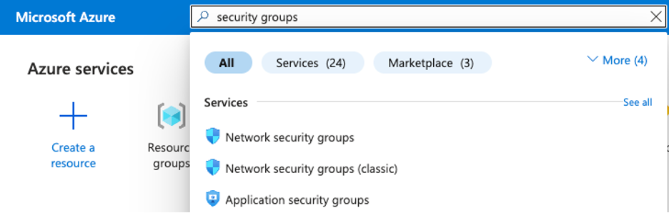
Figure: Search for Network Security Group
Step 2: Create and configure security group policy.
-
Click
Create. -
Assign the new security group to your resource group. This procedure uses
f5-ce-resource-groupas an example. -
Give the network security group an indicative name. In this procedure, it is
f5-ce-external-network-security-group. -
Click
Review + create. -
After you create the network security group, click on it to set up the inbound and outbound rules.
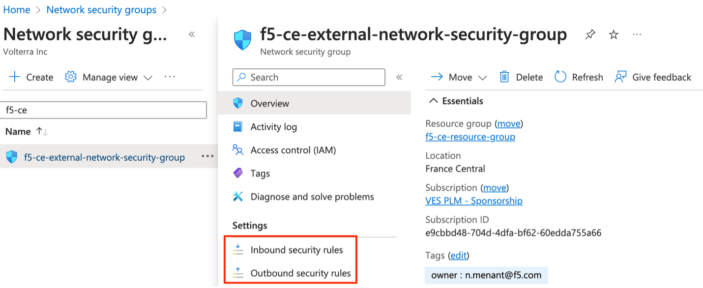
Figure: Select Network Security Group
Step 2.1: Add rule to inbound traffic.
Add an allow all rule to the inbound security rules. The default outbound rules already allow Internet traffic, so there is no need to change anything.
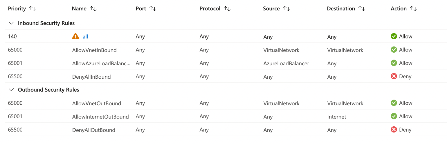
Figure: Inbound and Outbound Rules
Step 3: Verify rules created.
In the overview section for your network security group, you can see all the rules that have been created. Confirm the rules are as desired.
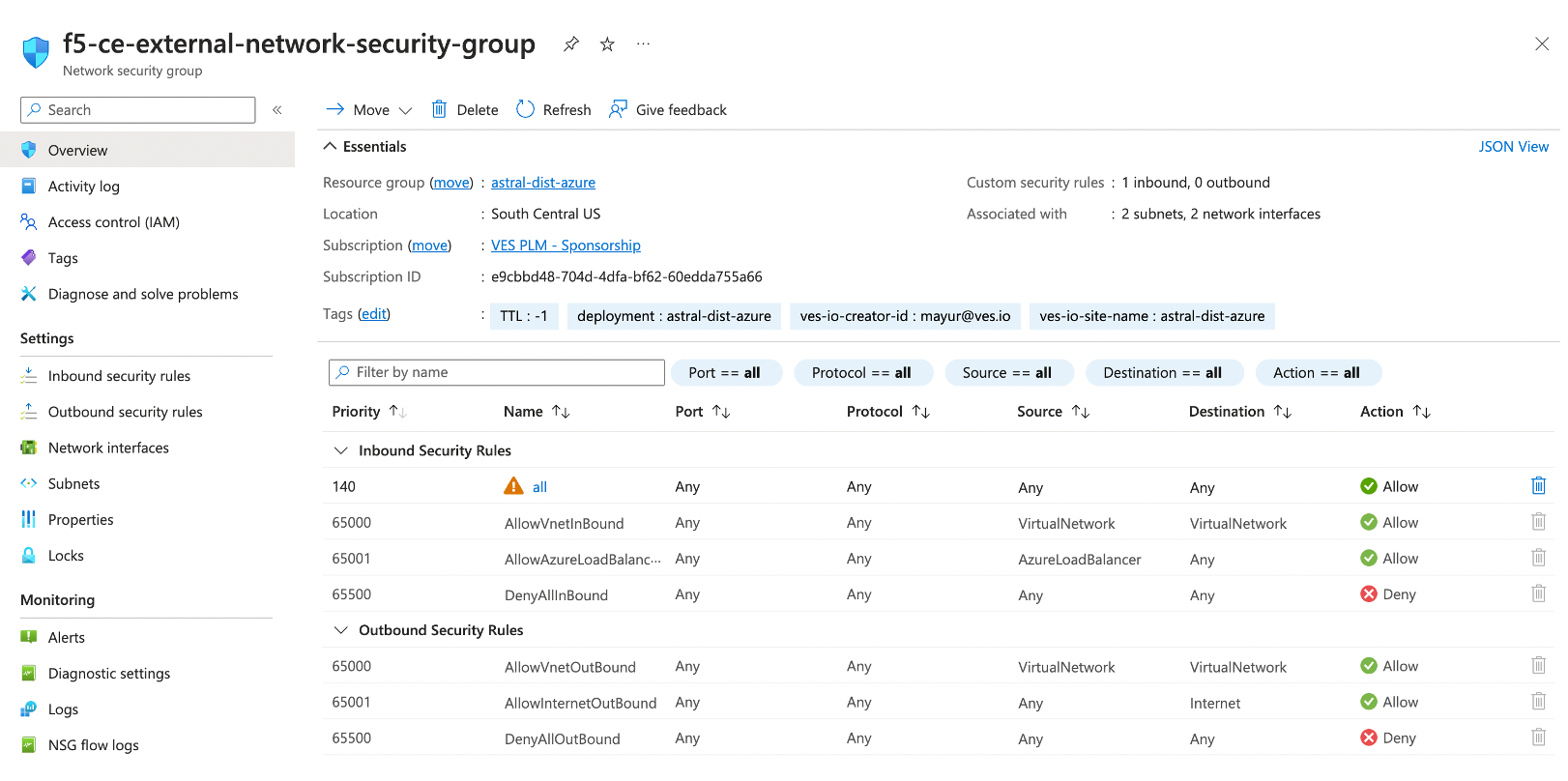
Figure: Verify Rules
Create SSH Key Pairs
You need to create key pairs for SSH login into the virtual machine for troubleshooting purposes.
Step 1: Navigate to SSH key creation page.
-
In the Azure portal, navigate to the
SSH keysservice. -
Click
Create.
Step 2: Configure SSH key pairs.
-
Verify the
SubscriptionandResource groupare correctly selected. -
In the
Key pair namefield, enter a name. -
Click
Review + create.
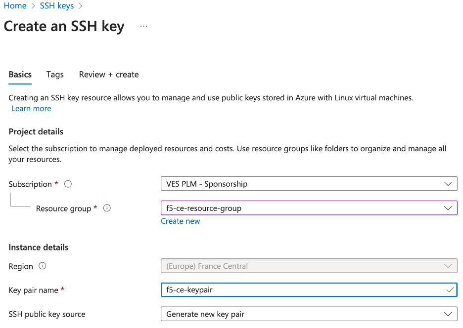
Figure: Create SSH Key Pairs
-
After successful validation, click
Create. -
Click
Download private key and create resourceto download the key pair locally to your machine since the pair will not be saved in Azure. You will need the key pair to log into the CE node. The private key pair file is namedf5-ce-keypair.pemas an example.
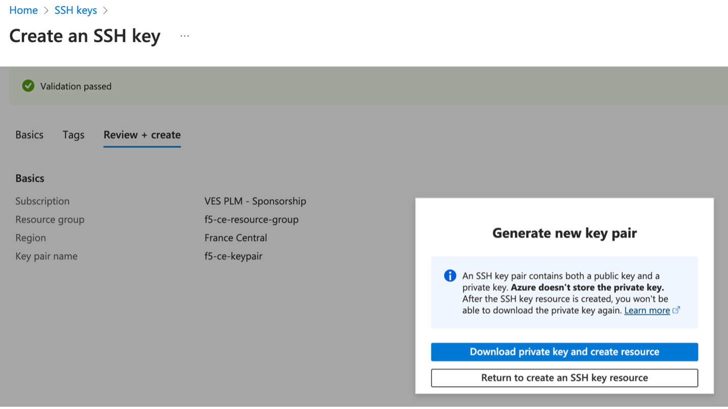
Figure: Download SSH Key Pairs
Existing Resource Group Details
In this procedure, we are deploying dual interface single-node and multi-node CE sites. Therefore, we need two subnets: SLI (Site Local Inside) and SLO (Site Local Outside). Note that workload subnets are generally used but are not a requirement to deploy a CE site.
Note: Azure subnets are not zonal constructs, so the same subnets can be used for deploying nodes in different AZs for a multi-node site.
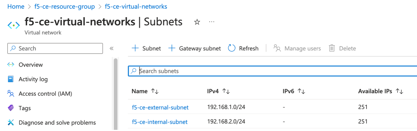
Figure: Existing Virtual Networks
Create Site Token
Create a site token or use an existing token. If you are configuring a multi-node site, use the same token for all nodes. To create the token, see the Create Site Token section.
Modify the User Data File
Download the raw .yml file to your machine and input the value of the site token into the Token field. See GitHub User Data File for more information. Afterwards, save the file on your machine as you will need it for the user data when creating the F5 CE virtual machine.
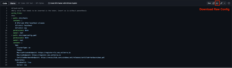
Figure: Raw YAML File
#cloud-config#Only values that need to be inserted are token and site name. Insert as is without parenthesiswrite_files:- path: /etc/hosts content: | # IPv4 and IPv6 localhost aliases 127.0.0.1 localhost 127.0.0.1 vip permissions: 0644 owner: root- path: /etc/vpm/config.yaml permissions: 0644 owner: root content: | Vpm: ClusterType: ce ClusterName: #### TO BE REPLACED BY THE F5XC SECURE MESH SITE NAME #### Token: #### TO BE REPLACED BY F5XC API TOKEN #### MauricePrivateEndpoint: https://register-tls.ves.volterra.io MauriceEndpoint: https://register.ves.volterra.io CertifiedHardwareEndpoint: https://vesio.blob.core.windows.net/releases/certified-hardware/azure.yml Kubernetes: EtcdUseTLS: True Server: vip CloudProvider: disabledDeploy Multi-Node Site
Follow these steps to create a three-node Secure Mesh Site.
Create Public IP Addresses
In Azure portal, create public IP addresses. You will need to create three public IP addresses since three nodes are being deployed for the CE site.
- Navigate to the
Public IP addressescreation page and clickCreate.
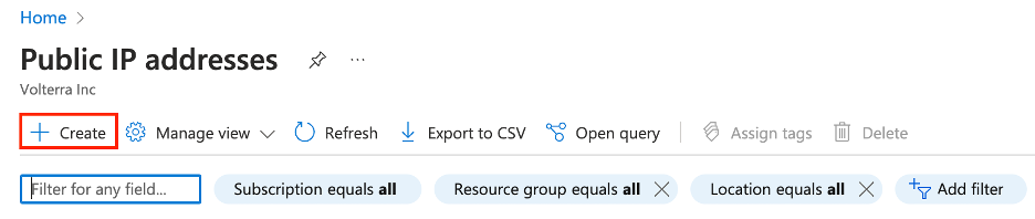
Figure: Create Public IP
-
Under
Configuration details, in theNamefield, enter a name for the Public IP. -
Leave the remaining options with their default values.
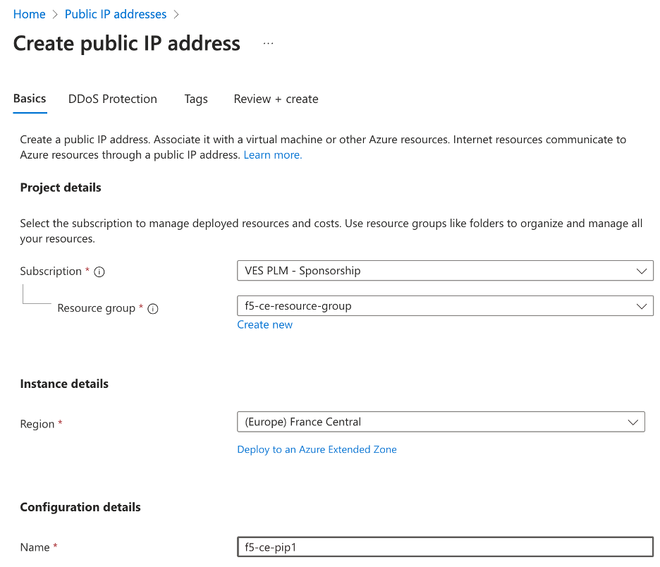
Figure: Create Public IP
-
Click
Review + create. -
After validation passes, click
Create. -
Repeat the above steps to create
f5-ce-pip2andf5-ce-pip3public IP addresses for nodes two and three.
Create the CE Virtual Machines
Create the F5 CE VM instances using the previously created parameters. F5 recommends that you create a table and fill it with the information prior to deploying the CE instance.
See table below for example parameters and explanations used for this procedure.
| Parameter | Value | Notes |
|---|---|---|
| Name | f5-ce-node1, f5-ce-node2, f5-ce-node3 | Names of CE node VM instances. |
| Region | France-central | Name of Azure region in which site is deployed. |
| Image Name | Volterra VoltMesh and VoltStack Node Free Plan | Located in Azure Marketplace. |
| Certified Hardware Name | azure-byol-multi-nic-voltmesh | This is the certified hardware name. |
| Instance Type | Standard_D8_v4 | Minimum instance requirements: 8 vCPUs, 32 GB RAM, 80 GB storage for Mesh nodes, and 100 GB storage for App Stack. Recommended instance types are Standard_D8_v4 and Standard_D16_v4. |
| Resource Group | f5-ce-resource-group | Created in Azure portal. |
| SLO Subnet ID | f5-ce-external-subnet | Existing subnet. |
| SLI Subnet ID | f5-ce-internal-subnet | Existing subnet. |
| Key Pair | f5-ce-keypair | Key pair created in Azure portal. |
| Security Groups | f5-ce-external-security-group | Name of security group created in Azure portal. |
| Public IP Addresses | f5-ce-pip1, f5-ce-pip2, f5-ce-pip3 | IP addresses created in Azure portal. |
| Site Name | f5-ce-demo | Equals ves-io-site-name value. |
| Token | Confidential. Value varies. | Value for site token ID generated in Distributed Cloud Console. |
| Storage | 80 GB for Mesh site/100 GB for App Stack recommended. | Minimum disk space required. |
Step 1: Create new virtual machine.
- In Azure portal, within your resource group, click
Create.
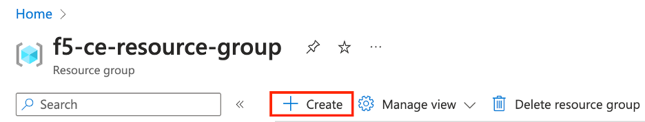
Figure: Create VM
-
Use the search bar to locate the right CE image. You can search for "Volterra Free Plan." This procedure uses the image for Volterra VoltMesh and VoltStack Node Free Plan. This plan image corresponds to the
azure-byol-multi-nic-voltmeshcertified hardware. -
After you find the image, click
Create.
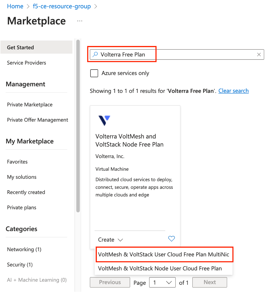
Figure: Select VM Image
Step 2: Configure new virtual machine.
- Enter a VM name.
Important: The name of the VM should not have "." in it. For example, the hostname can be node-0 or node0, but it cannot be node.f5.com since it is not supported. Your node VM name must adhere to DNS-1035 label requirements. This means the name must consist of lower case alphanumeric characters or “-“, start with an alphabetic character, and end with an alphanumeric character.
If configuring a multi-node site, each node hostname must be unique.
- Ensure the correct region and availability zone are selected.
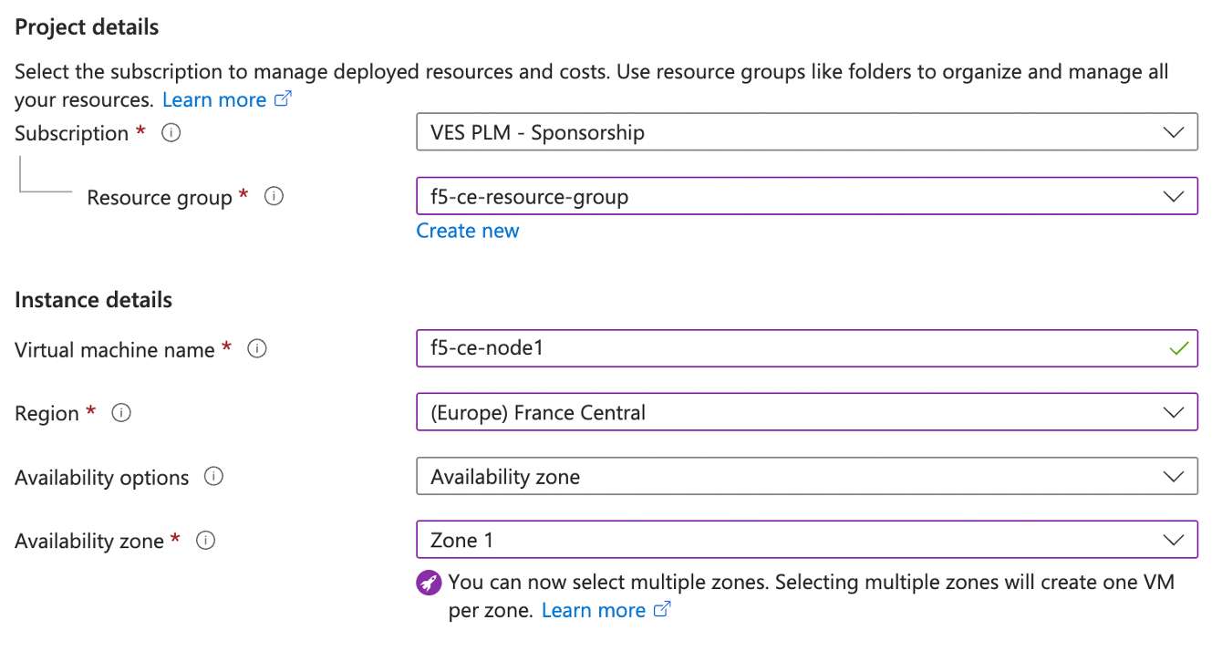
Figure: Configure VM
- From the
Sizemenu, choose the instance type. This procedure usesStandard_D8_v4as an example. This instance type is the minimum required to deploy an F5 CE Site to Azure cloud.
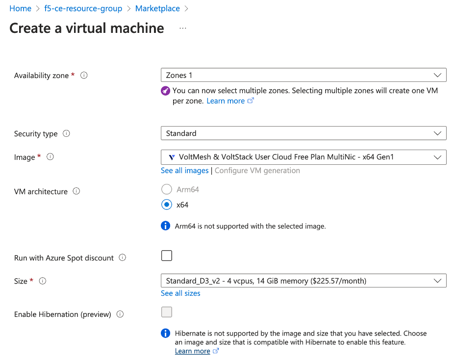
Figure: Configure VM Instance Type
-
From the
SSH public key sourcemenu, assign the previously created SSH key pair. -
In the
Usernamefield, Entercloud-useras the default user to SSH log into the CE instance.
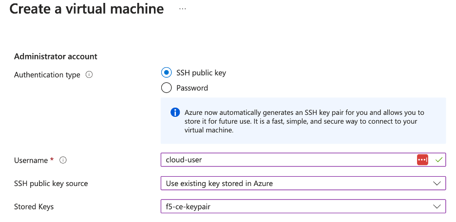
Figure: Configure VM Username
-
Click
Next:Disk. -
From the
OS disk sizemenu, select128 GiB (E10).
Step 3: Configure virtual machine networking.
-
Click
Next:Networking. -
Ensure the following parameters for network interface configuration:
-
From the
Virtual networkmenu, select the network. -
From the
Subnetmenu, select the external interface.
-
Important: You cannot create/assign the internal interface to the virtual machine in this step. It will be added at a later step.
-
From the
Public IPmenu, select the IP previously created. -
For the
NIC network security groupoption, selectAdvanced. This option is needed so that you are able to select the network security group. -
From the
Configure network security groupmenu, select the security group previously created. -
Select the
Delete NIC when VM is deletedoption.
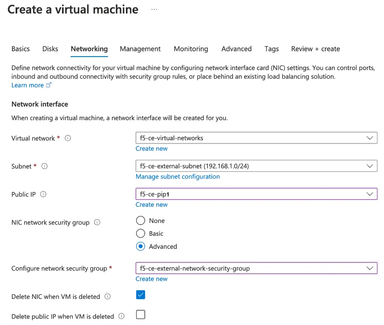
Figure: Configure VM Networking
Step 4: Configure advanced settings.
-
Click the
Advancedtab to skip theManagementandMonitoringconfiguration. -
In the
Custom datafield, copy and paste the user data file information (which includes the site token).
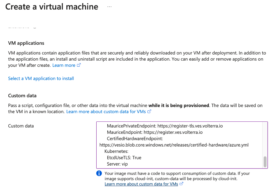
Figure: User Data
Step 5: Complete VM creation.
Click on Review + create. After validation process completes successfully, click Create.
Step 6: Track VM deployment progress.
You can track deployment progress by connecting to your instance's public IP on port 65500. It may take a few minutes for the web interface to appear.
The default username is admin and the default password is Volterra123. You will be required to change the default password on your first login attempt.
The CE will show in Approval state. This means that the CE is awaiting registration approval from F5 Distributed Cloud Console. Before approving registration, you need to add a second interface to the CE site.
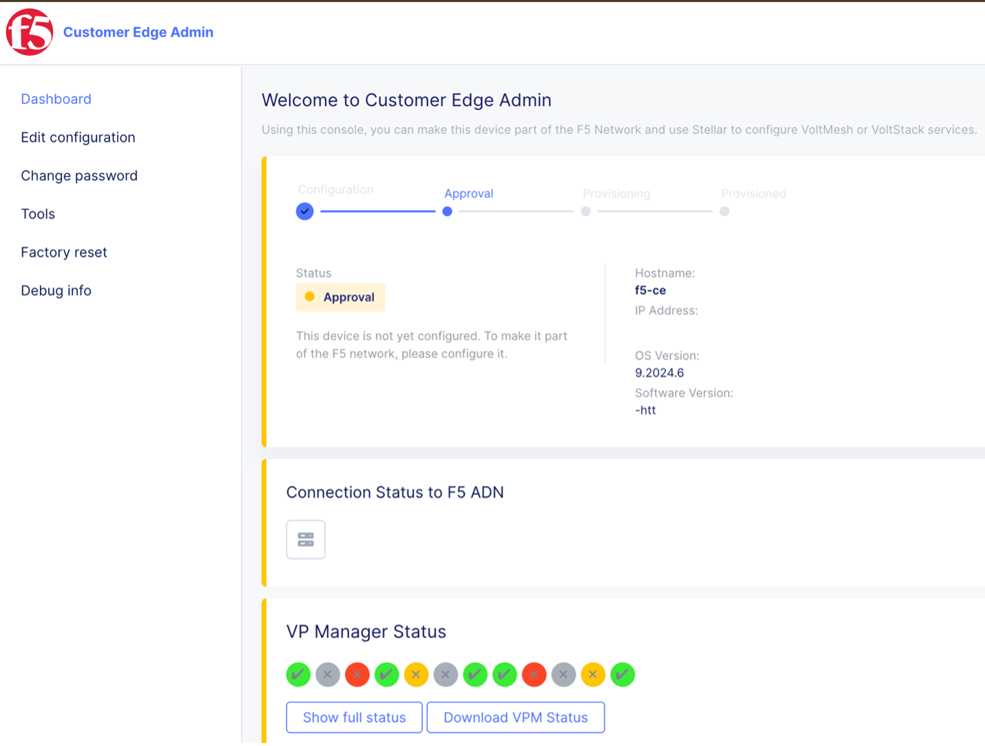
Figure: Site Local UI
Step 7: Create VM instances for nodes two and three.
-
Repeat above steps 1-6 to deploy
f5-ce-node2andf5-ce-node3in AZ 2 and 3, respectively. -
Ensure you associate the correct public IP address with each node.
Add Second Interface to Multi-Node Site
-
In Azure portal, select your VM and click
Stop. -
After the VM stops, click
Network settings. Then clickAttach network interface.
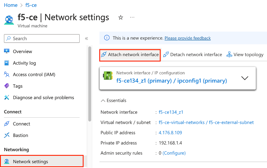
Figure: Add Second Interface
- Click
Create and attach network interface.
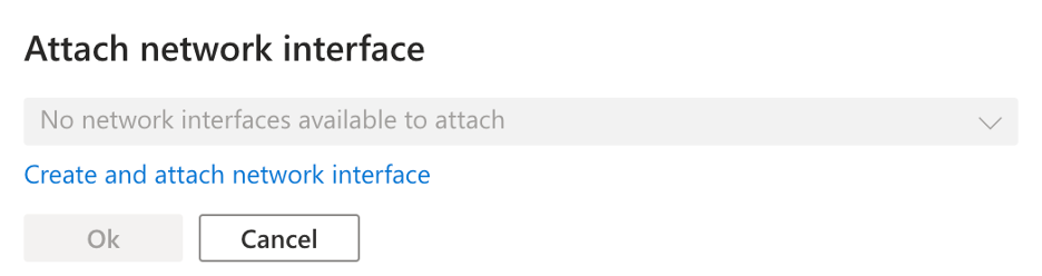
Figure: Add Second Interface
-
Select the resource group previously created for this VM.
-
In the
Namefield, enter a new name for this second interface. -
In the
Subnetfield, enter a new name for this interface. Make sure to reference that this is an internal interface since the external interface was previously created.
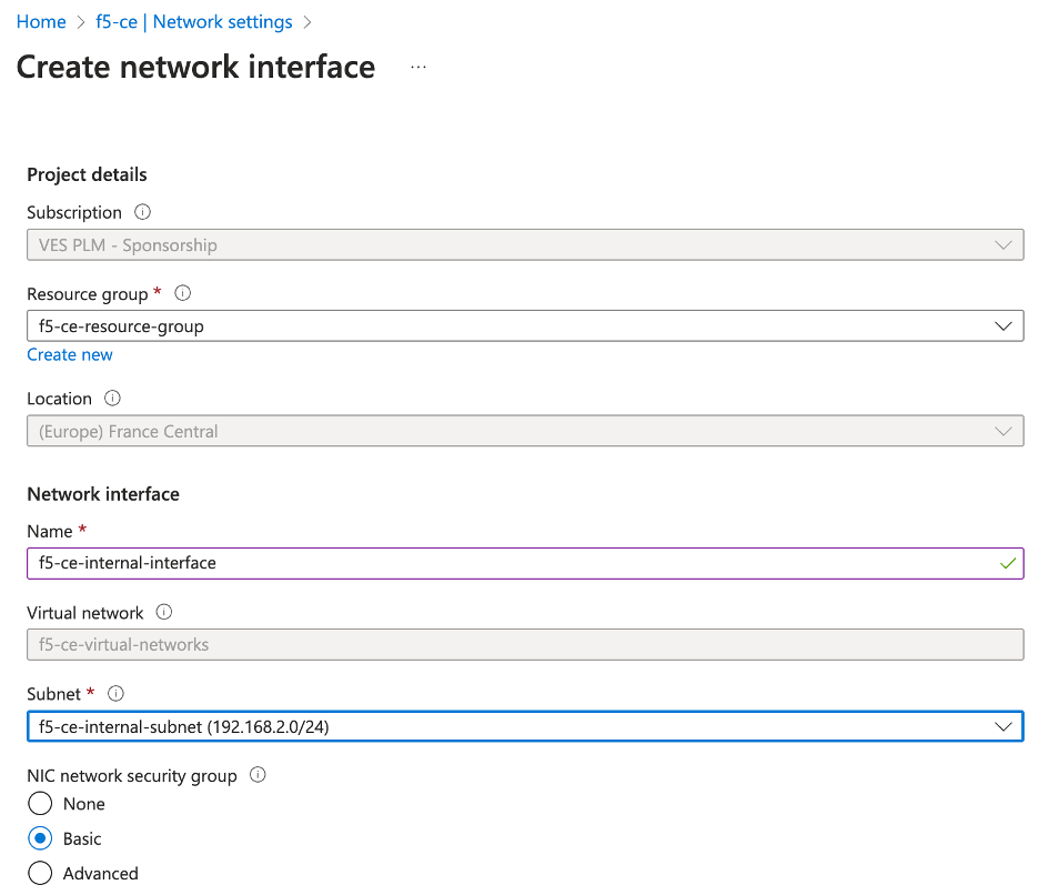
Figure: Add Second Interface
-
Click
Create. -
After the second interface is attached to your VM, restart the VM.
-
Connect to the CE's local UI to verify that the second interface was properly configured.
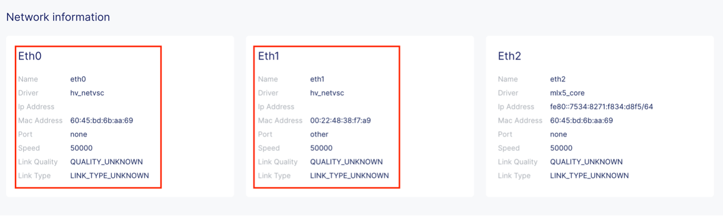
Figure: CE Site Local UI
- Repeat above steps to add second interface for
f5-ce-node2andf5-ce-node3.
Deploy Single-Node Site
Follow these steps to create a single-node Secure Mesh Site.
Create Public IP Address
In Azure portal, create a public IP address. You will need to create one public IP address since only one node is being deployed for the CE site.
- Navigate to the
Public IP addressescreation page and clickCreate.
Figure: Create Public IP
-
Under
Configuration details, in theNamefield, enter a name for the Public IP. -
Leave the remaining options with their default values.
Figure: Create Public IP
-
Click
Review + create. -
After validation passes, click
Create.
Create the CE Virtual Machine
Create the F5 CE VM instance using the previously created parameters. F5 recommends that you create a table and fill it with the information prior to deploying the CE instance.
See table below for example parameters and explanations used for this procedure.
| Parameter | Value | Notes |
|---|---|---|
| Name | f5-ce | Name of CE node VM instance. |
| Region | France-central | Name of Azure region in which site is deployed. |
| Image Name | Volterra VoltMesh and VoltStack Node Free Plan | Located in Azure Marketplace. |
| Certified Hardware Name | azure-byol-multi-nic-voltmesh | This is the certified hardware name. |
| Instance Type | Standard_D8_v4 | Minimum instance requirements: 8 vCPUs, 32 GB RAM, 80 GB storage for Mesh nodes, and 100 GB storage for App Stack. Recommended instance types are Standard_D8_v4 and Standard_D16_v4. |
| Resource Group | f5-ce-resource-group | Created in Azure portal. |
| SLO Subnet ID | f5-ce-external-subnet | Existing subnet. |
| SLI Subnet ID | f5-ce-internal-subnet | Existing subnet. |
| Key Pair | f5-ce-keypair | Key pair created in Azure portal. |
| Security Groups | f5-ce-external-security-group | Name of security group created in Azure portal. |
| Public IP Address | f5-ce-pip | IP address created in Azure portal. |
| Site Name | f5-ce-demo | Equals ves-io-site-name value. |
| Token | Confidential. Value varies. | Value for site token ID generated in Distributed Cloud Console. |
| Storage | 80 GB for Mesh site/100 GB for App Stack recommended. | Minimum disk space required. |
Step 1: Create new virtual machine.
- In Azure portal, within your resource group, click
Create.
Figure: Create VM
-
Use the search bar to locate the right CE image. You can search for "Volterra Free Plan." This procedure uses the image for Volterra VoltMesh and VoltStack Node Free Plan. This plan image corresponds to the
azure-byol-multi-nic-voltmeshcertified hardware. -
After you find the image, click
Create.
Figure: Select VM Image
Step 2: Configure new virtual machine.
- Enter a VM name.
Important: The name of the VM should not have "." in it. For example, the hostname can be node-0 or node0, but it cannot be node.f5.com since it is not supported. Your node VM name must adhere to DNS-1035 label requirements. This means the name must consist of lower case alphanumeric characters or “-“, start with an alphabetic character, and end with an alphanumeric character.
If configuring a multi-node site, each node hostname must be unique.
- Ensure the correct region and availability zone are selected.
Figure: Configure VM
- From the
Sizemenu, choose the instance type. This procedure usesStandard_D8_v4as an example. This instance type is the minimum required to deploy an F5 CE Site to Azure cloud.
Figure: Configure VM Instance Type
-
From the
SSH public key sourcemenu, assign the previously created SSH key pair. -
In the
Usernamefield, Entercloud-useras the default user to SSH log into the CE instance.
Figure: Configure VM Username
-
Click
Next:Disk. -
From the
OS disk sizemenu, select128 GiB (E10).
Step 3: Configure virtual machine networking.
-
Click
Next:Networking. -
Ensure the following parameters for network interface configuration:
-
From the
Virtual networkmenu, select the network. -
From the
Subnetmenu, select the external interface.
-
Important: You cannot create/assign the internal interface to the virtual machine in this step. It will be added at a later step.
-
From the
Public IPmenu, select the IP previously created. -
For the
NIC network security groupoption, selectAdvanced. This option is needed so that you are able to select the network security group. -
From the
Configure network security groupmenu, select the security group previously created. -
Select the
Delete NIC when VM is deletedoption.
Figure: Configure VM Networking
Step 4: Configure advanced settings.
-
Click the
Advancedtab to skip theManagementandMonitoringconfiguration. -
In the
Custom datafield, copy and paste the user data file information (which includes the site token).
Figure: User Data
Step 5: Complete VM creation.
Click on Review + create. After validation process completes successfully, click Create.
Step 6: Track VM deployment progress.
You can track deployment progress by connecting to your instance's public IP on port 65500. It may take a few minutes for the web interface to appear.
The default username is admin and the default password is Volterra123. You will be required to change the default password on your first login attempt.
The CE will show in Approval state. This means that the CE is awaiting registration approval from F5 Distributed Cloud Console. Before approving registration, you need to add a second interface to the CE site.
Figure: Site Local UI
Add Second Interface to Single-Node Site
-
In Azure portal, select your VM and click
Stop. -
After the VM stops, click
Network settings. Then clickAttach network interface.
Figure: Add Second Interface
- Click
Create and attach network interface.
Figure: Add Second Interface
-
Select the resource group previously created for this VM.
-
In the
Namefield, enter a new name for this second interface. -
In the
Subnetfield, enter a new name for this interface. Make sure to reference that this is an internal interface since the external interface was previously created.
Figure: Add Second Interface
-
Click
Create. -
After the second interface is attached to your VM, restart the VM.
-
Connect to the CE's local UI to verify that the second interface was properly configured.
Figure: CE Site Local UI
Create and Register Secure Mesh Site
Follow the Create Secure Mesh Site guide to create a Secure Mesh Site object and register the nodes to the site.
Additional Settings for Application Traffic Flow to Work
For services like network connectivity, application connectivity, and delivery to work correctly, you need to enable additional settings for Azure CE nodes. You need to enable the IP forwarding setting on each NIC of the Azure CE node.
-
In Azure portal, navigate to
Network settingsfor the CE node. -
Click the NIC for the CE node.
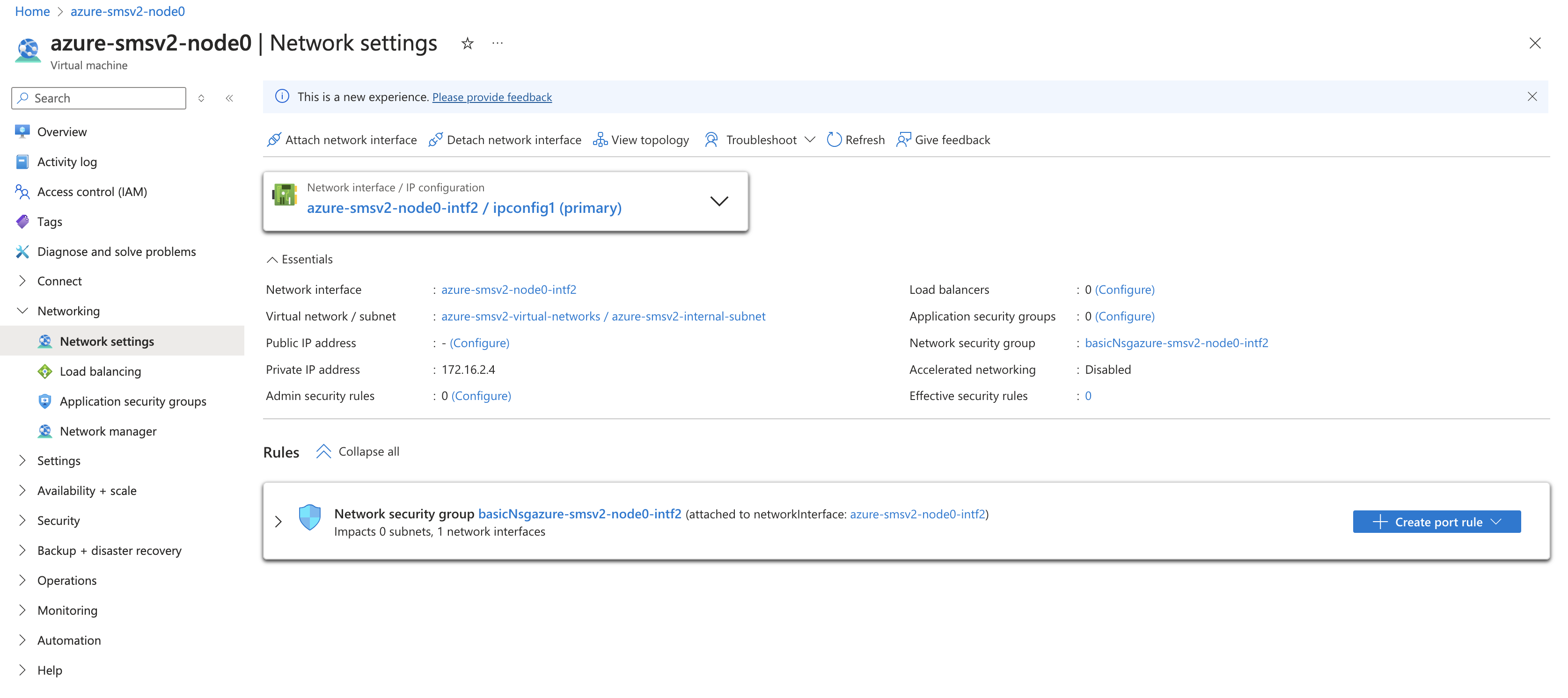
Figure: Node NIC Settings
Select Settings > IP configurations and enable the Enable IP forwarding checkbox.
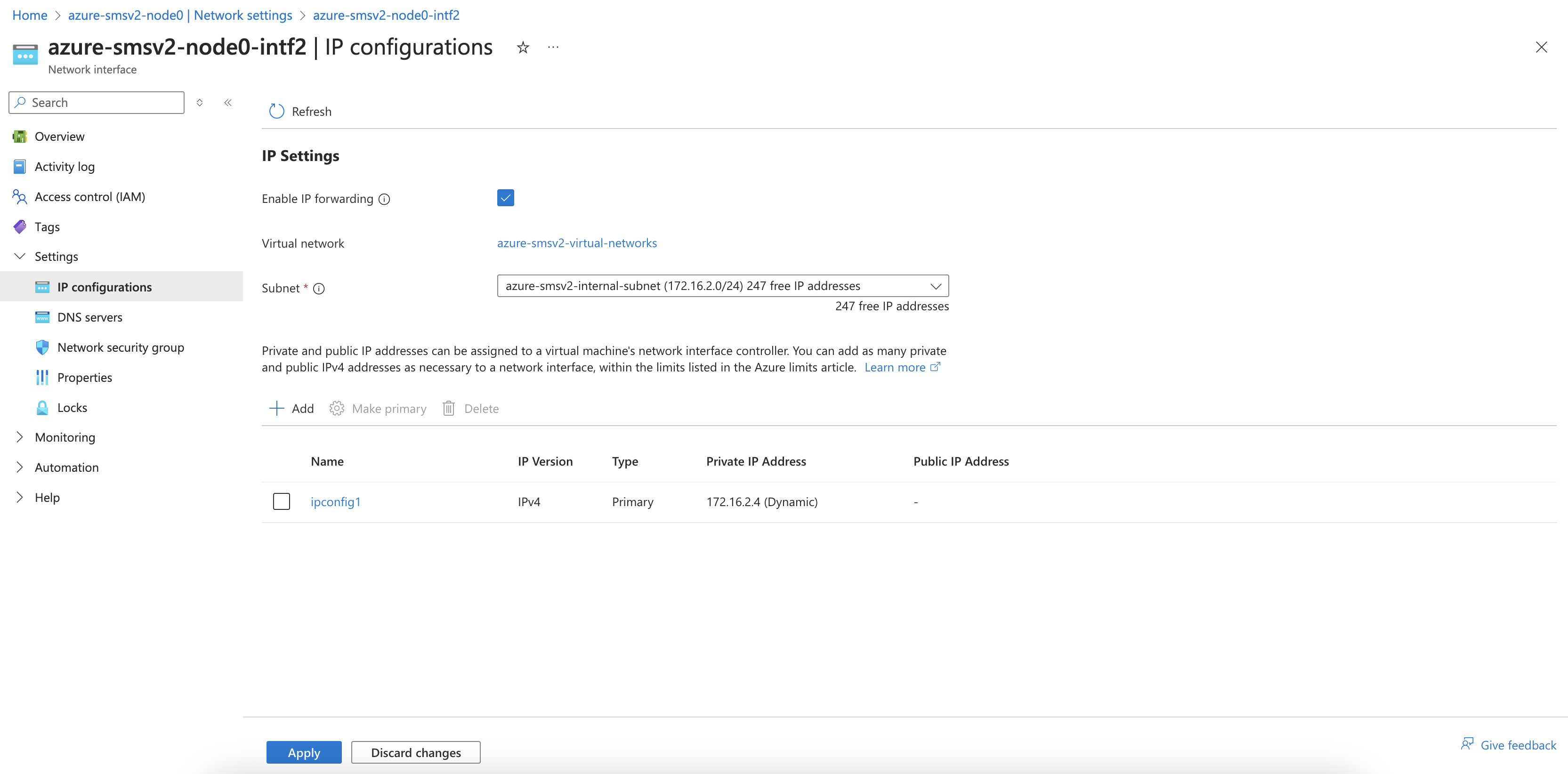
Figure: Enable IP Forwarding
Troubleshooting
For troubleshooting and opening a support case, see the Troubleshooting Manual Site Deployment Registration Issues guide. It provides step-by-step instructions to debug and resolve the issues that may arise due to Distributed Cloud published Terraform errors, networking and security misconfiguration, or CE internal process issues. The guide also provides instructions for contacting the F5 Distributed Cloud Support Team if you are unable to resolve the issue.
Concepts
- System Overview
- Core Concepts
- Networking
- F5 Distributed Cloud - Customer Edge
- F5 Distributed Cloud Site
References
On this page:
- Objective
- Site Types and Scenarios
- Considerations for Sites Behind NAT Gateway
- Prerequisites
- Procedure
- Create External Network Security Group
- Create SSH Key Pairs
- Existing Resource Group Details
- Create Site Token
- Modify the User Data File
- Deploy Multi-Node Site
- Create Public IP Addresses
- Create the CE Virtual Machines
- Add Second Interface to Multi-Node Site
- Deploy Single-Node Site
- Create Public IP Address
- Create the CE Virtual Machine
- Add Second Interface to Single-Node Site
- Create and Register Secure Mesh Site
- Additional Settings for Application Traffic Flow to Work
- Troubleshooting
- Concepts
- References