Deploy VMware Site
Objective
Important: This is a legacy workflow for deploying Customer Edge (CE) Sites and is not recommended to use. A new workflow for deploying Customer Edge (CE) Sites has been introduced and is now Generally Available (GA). F5 recommends that you use the new Secure Mesh Site (v2) workflow for all Customer Edge deployments. You can find this workflow here.
This document provides instructions on how to install an F5® Distributed Cloud Services single-node site or multi-node site on VMware ESXi.
Using the instructions provided in this document, you can deploy a Distributed Cloud Services site by deploying a virtual machine (VM) from an Open Virtual Appliance (OVA) file containing the node as the appliance.
Prerequisites
-
A Distributed Cloud Services Account. If you do not have an account, see Getting Started with Console.
-
Secure Mesh Site or App Stack Site object on F5 Distributed Cloud Console.
-
VMware vSphere Hypervisor (ESXi) 7.0 or later. The examples in this document are based on version 7.0.0.
-
At least one interface with Internet reachability.
-
A Distributed Cloud Services VMware OVA image file. Click here to download the OVA image file.
-
Resources required per VM: Minimum 8 vCPUs and 32 GB RAM. 80 GB is the minimum amount required for storage. However, to deploy an F5® Distributed Cloud App Stack Site, 100 GB is the recommended minimum amount of storage. For a full listing of the resources required, see the Customer Edge Site Sizing Reference guide. All the nodes in a given CE Site should have the same resources regarding the compute, memory, and disk storage. When deploying in cloud environments, these nodes should use the same instance flavor.
-
Allow traffic from and to the Distributed Cloud public IP addresses to your network and allowlist related domain names. See F5 Customer Edge IP Address and Domain Reference for Firewall or Proxy Settings guide for the list of IP addresses and domain names.
-
Internet Control Message Protocol (ICMP) needs to be opened between the CE nodes on the Site Local Outside (SLO) interfaces. This is needed to ensure intra-cluster communication checks.
Important: After you deploy the CE Site, the IP address for the SLO interface cannot be changed. Also, the MAC address cannot be changed.
Create OVF Template from OVA File
VMware uses an OVA (Open Virtualization Appliance) file to store various files associated with a virtual machine (VM). The OVA file is stored in the Open Virtualization Format (OVF) as a TAR archive.
F5 Distributed Cloud packages its software in an OVA template file that allows you to add a pre-configured virtual machine to your vCenter Server or ESXi inventory. You can use vApp properties of the OVA template to configure the site and specify the data (site name, site token, location, and more) required to register the site on the F5 Distributed Cloud Console.
Create OVF Template Using vSphere Client
To use the VMware vSphere Client to create an OVA template, upload to the vSphere Client the OVA file that you downloaded from F5 Distributed Cloud Services.
Step 1: Login to the vSphere Client.
Log in to the vSphere Client and click Menu> Hosts and Clusters.
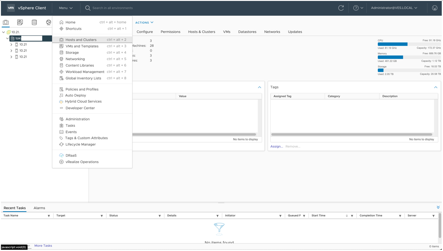
Figure: Hosts and Clusters
Step 2: Deploy the OVF Template.
- Right-click
Data Centerand clickDeploy OVF Template.
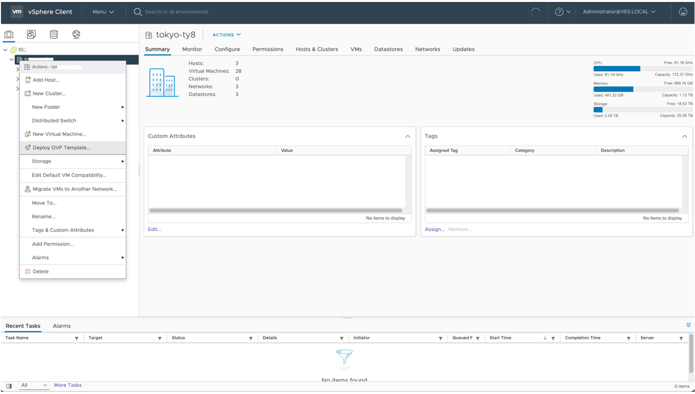
Figure: Deploy an OVF template
- On the
Select an OVF templatepage, clickLocal fileto upload the F5 Distributed Cloud VMware OVA image file that you downloaded. Then clickNEXT.
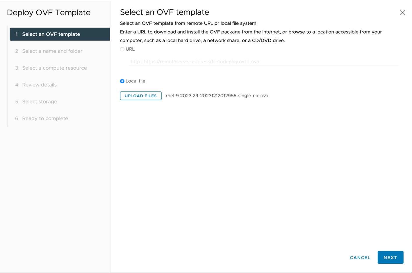
Figure: Select an OVF template page
- On the
Select a name and folderpage, enter a uniqueVirtual machine nameand select a folder to store the OVF template. Then clickNEXT.
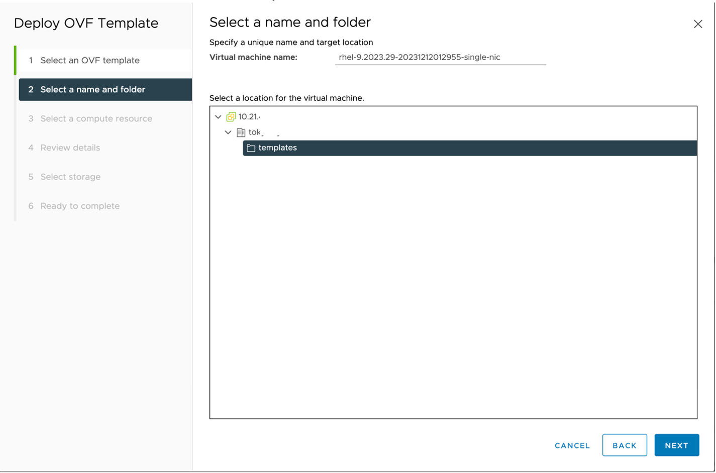
Figure: Select a name and folder page
- On the
Select a compute resourcepage, select a host to run the template.
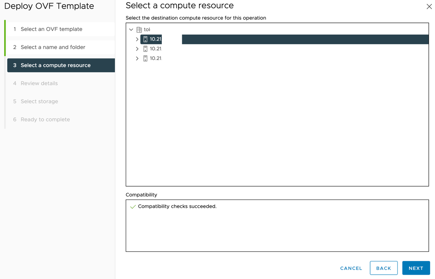
Figure: Select a compute resource page
- On the
Review detailspage, verify the template details and clickNEXT.
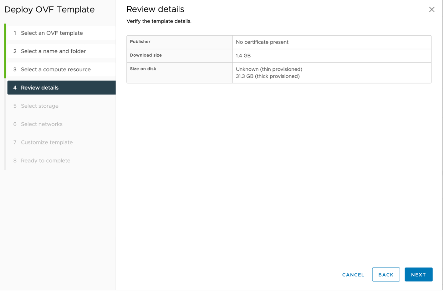
Figure: Review details page
- On the
Select storagepage, select where you want to store the files for the deployed template and then clickNEXT.
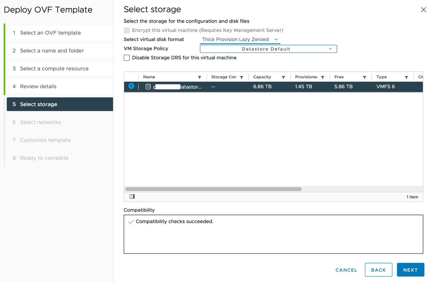
Figure: Select storage page
- On the
Select networkspage, for theSource NetworknamedOUTSIDE, select aDestination Network. TheDestination Networkmust have an internet connection. Then clickNEXT.
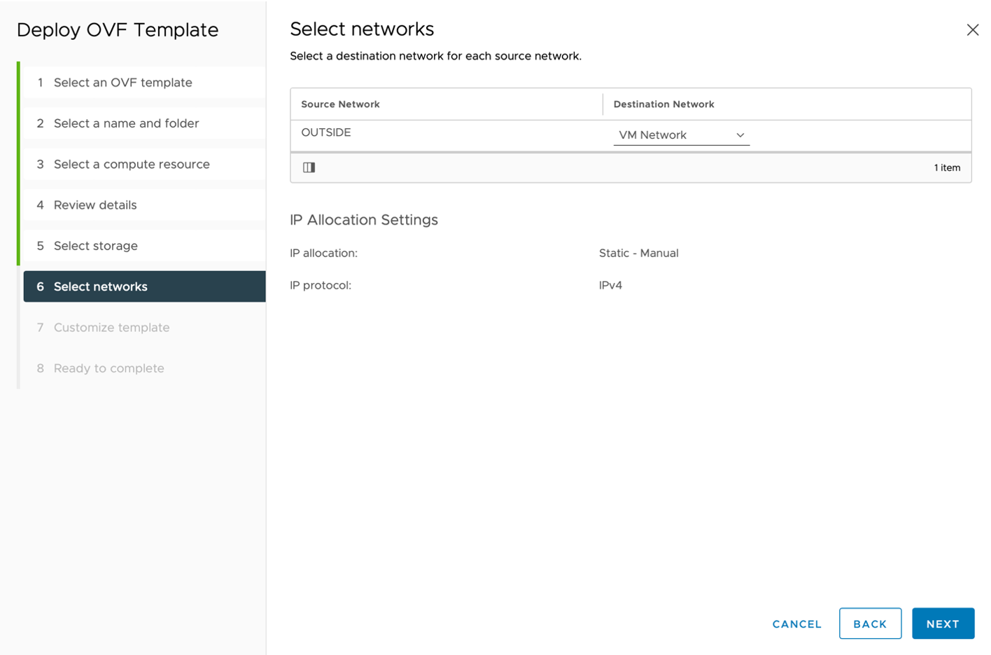
Figure: Select networks page
- On the
Customize templatepage, keep the default values for all deployment properties and clickNEXT.
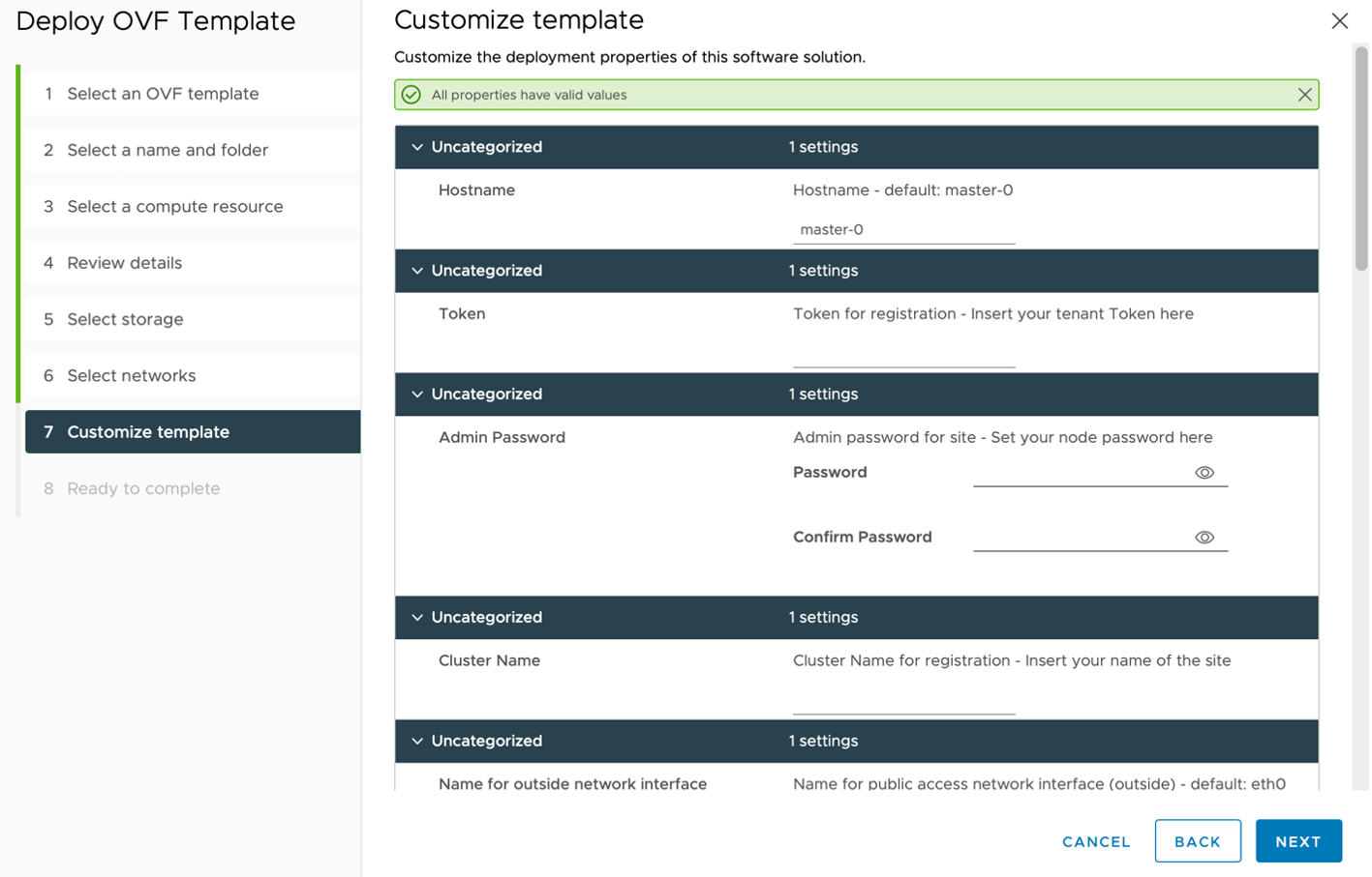
Figure: Customize template page
- On the
Ready to completepage, review your template information and then clickFINISH.
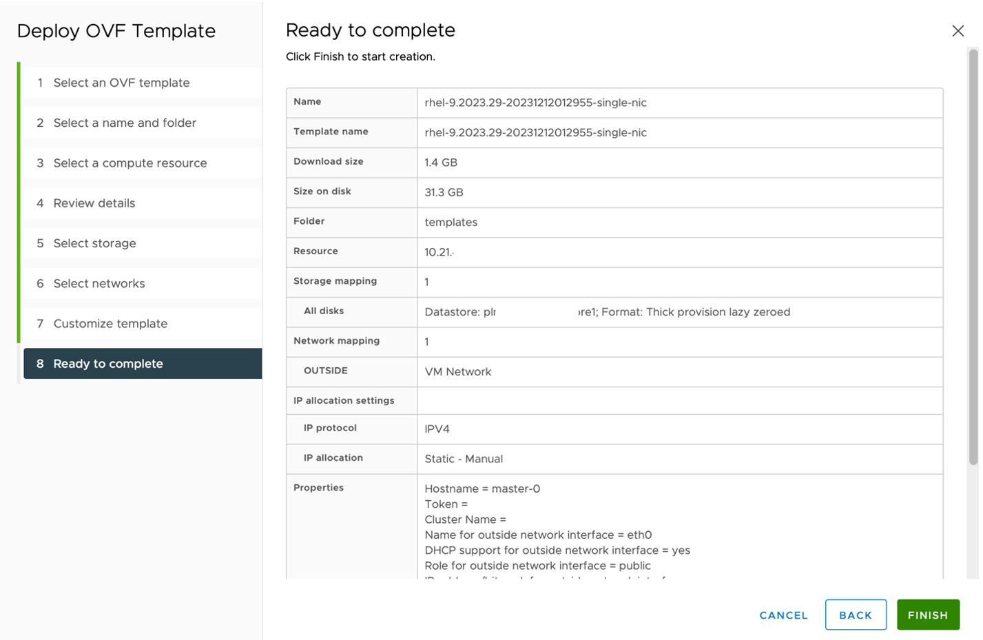
Figure: Ready to complete page
Step 3: Convert VM to Template.
-
Locate the VM you created in the previous steps and go to
Menu>VMs and Templates. -
Right-click on
rhel-9.2023.29-20231212012955-single-nicand clickTemplate>Convert to template.
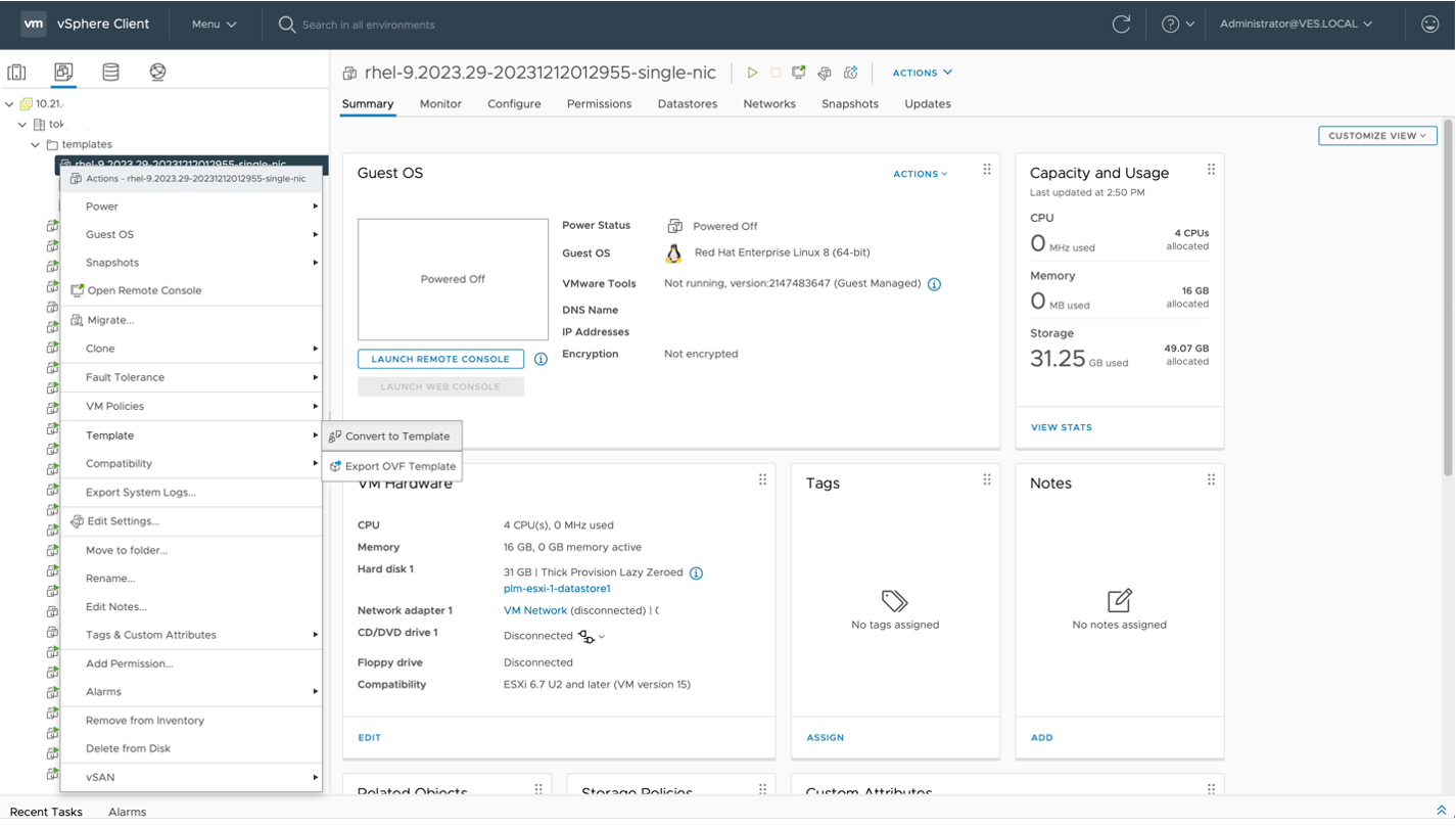
Figure: Convert to template
- Click
YESto confirm the conversion.

Figure: Confirm Convert message
Create an OVF Template Using the VMware OVF Tool
The VMware Open Virtualization Format (OVF) Tool is a command-line utility that lets you import and export OVF packages to and from VMware products.
To download the OVF Tool and view the VMware documentation, go to the official developer portal.
Use the following OVF tool import commands to create an OVA template using the F5 Distributed Cloud Site image file.
$ ovftool --acceptAllEulas --allowAllExtraConfig --importAsTemplate \--name=rhel-9.2023.29-20231212012955-single-nic \--datastore=<datastore_name> \--net:"OUTSIDE=<network_name>" \--vmFolder=<folder_name> \rhel-9.2023.29-20231212012955-single-nic.ova \vi://<username><password>@<vCenter_IP>/<datacenter>/host/<host_IP>/
Output:Opening OVA source: rhel-9.2023.29-20231212012955-single-nic.ovaThe manifest validates.Opening VI target:vi://user%40domain@10.21.X.X:443/datacenter/host/10.21.X.X/Warning: - Line 149: Unable to parse 'enableMPTSupport' for attribute 'key' on element 'Config'.Deploying to VI:vi://user%40domain@10.21.X.X:443/datacenter/host/10.21.X.X/Transfer CompletedCompleted successfully.
The following table provides information about the parameters above.
| Name | Description |
|---|---|
| datastore_name | Name of the data store/storage on the ESXi host |
| network_name | Name of the network adapter on the ESXi host with internet connectivity |
| folder_name | VM and template folder on vSphere |
| username | Username of the vSphere client |
| password | Password of the vSphere client user |
| vCenter_IP | IP address of the vSphere client |
| datacenter | Name of the data center configured on the vCenter server |
| host_IP | IP address of the ESXi hosts connected on the vCenter server |
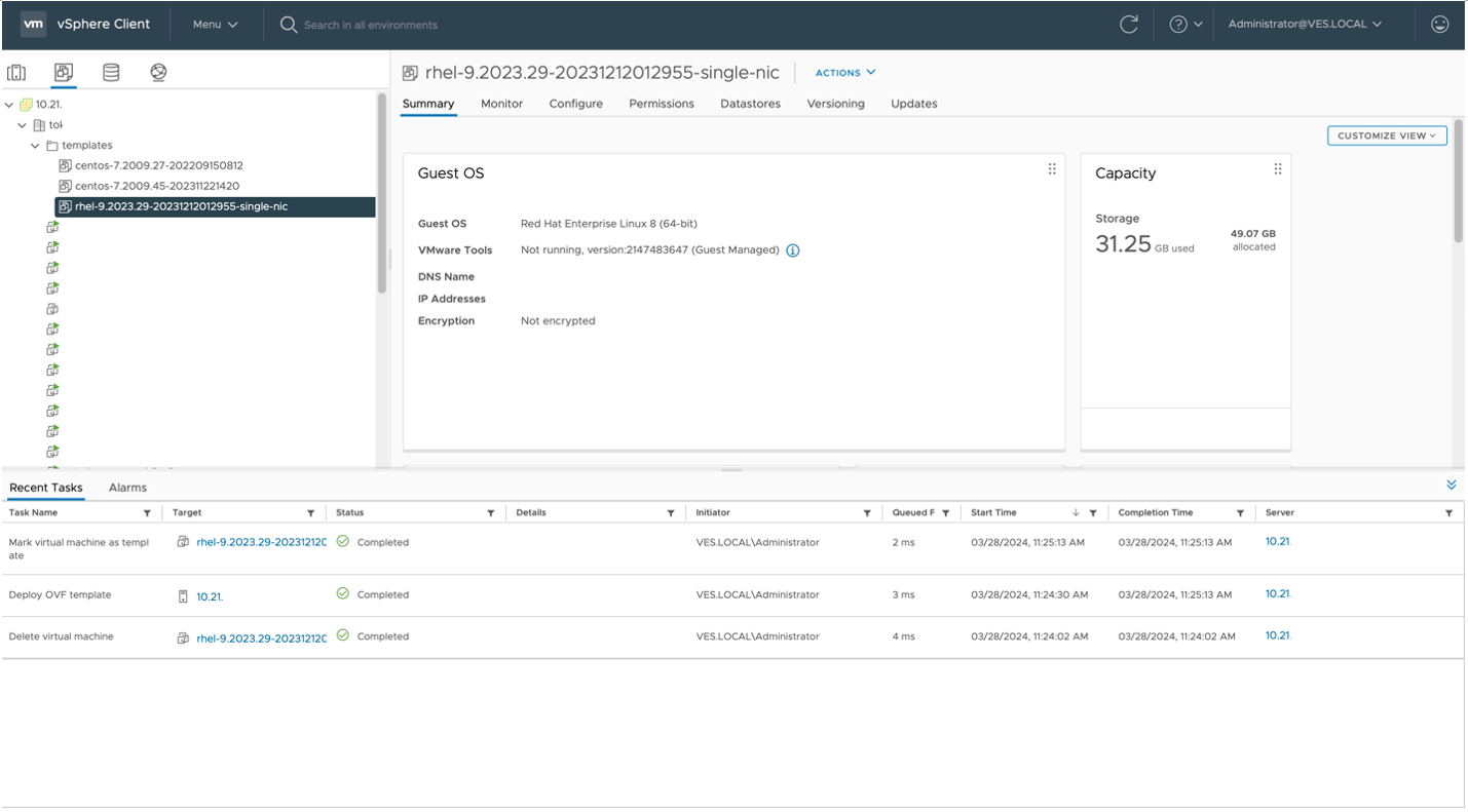
Figure: vSphere Client
Deploy a Site
Deploy a Site Using vSphere Client
To create a site from vSphere, use the OVF template created on the previous step.
Step 1: Locate the OVF template and create a new VM.
- Log in to the vSphere Client and click
Menu>VMs and Templates.
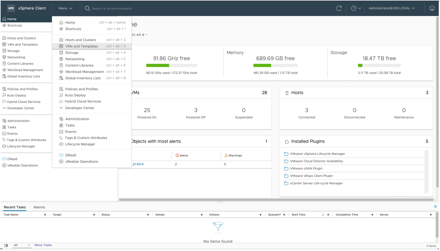
Figure: VMs and Templates
- Locate the new OVF template. Right-click on the template and then click
New VM from This Template.
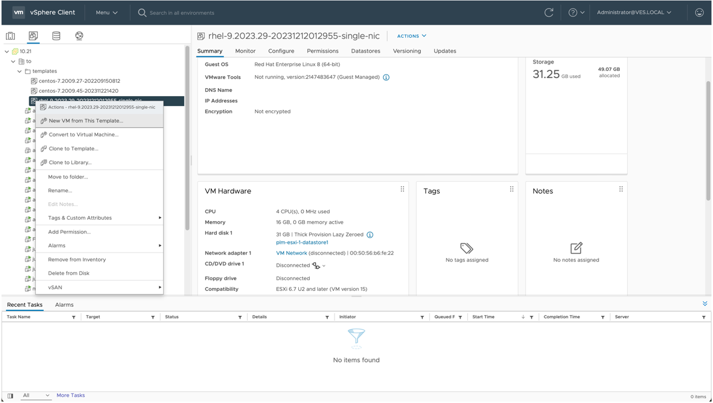
Figure: New VM from This Template
Step 2: Configure the VM.
On the Select a name and folder page, enter a Virtual machine name for the VM and select the folder where you want to deploy the VM. Then click NEXT.
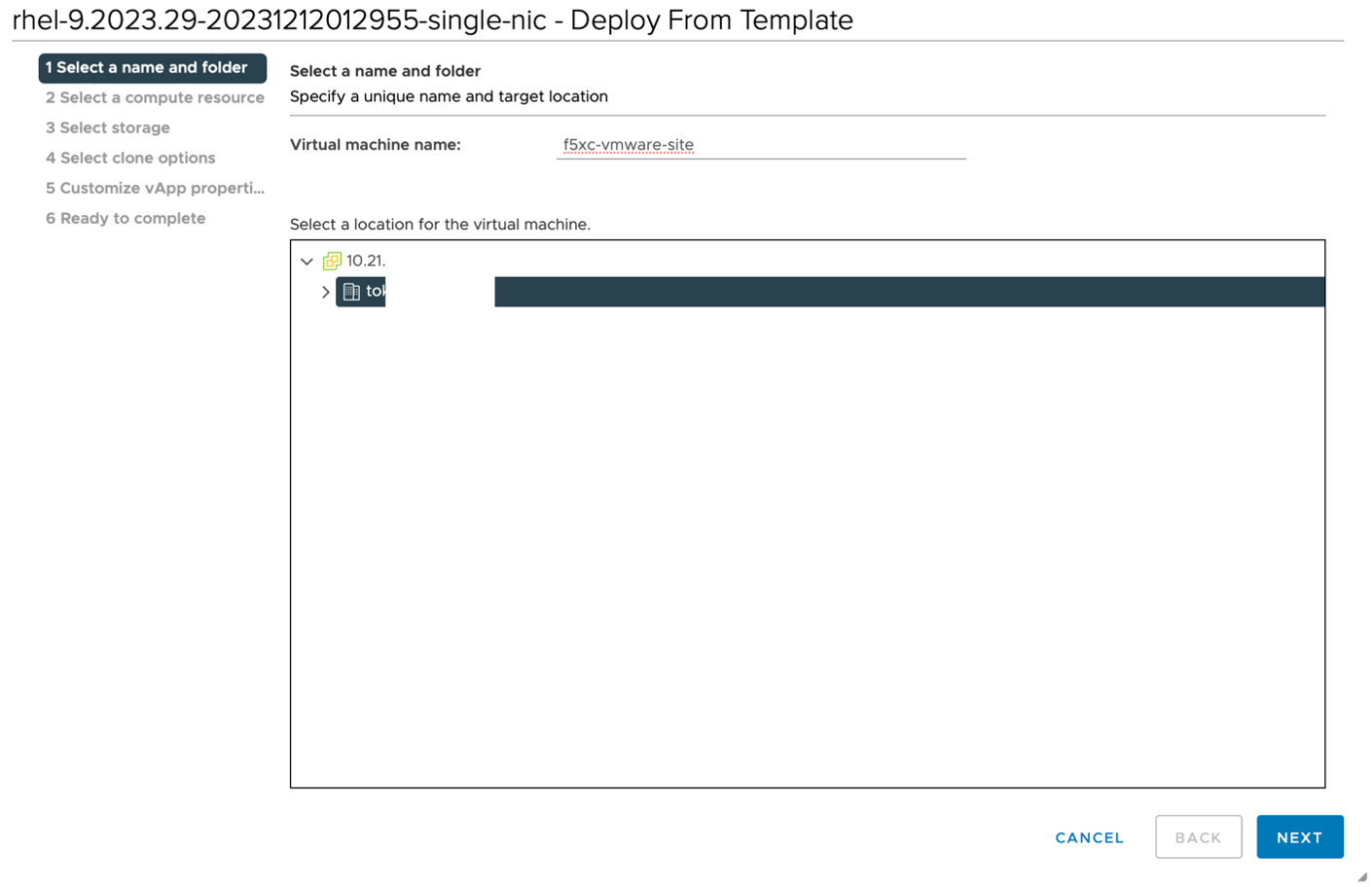
Figure: Select a name and folder page
Step 3: Select the ESXi compute resource.
On the Select a compute resource page, select the ESXi host target where you want to deploy the VM and click NEXT.
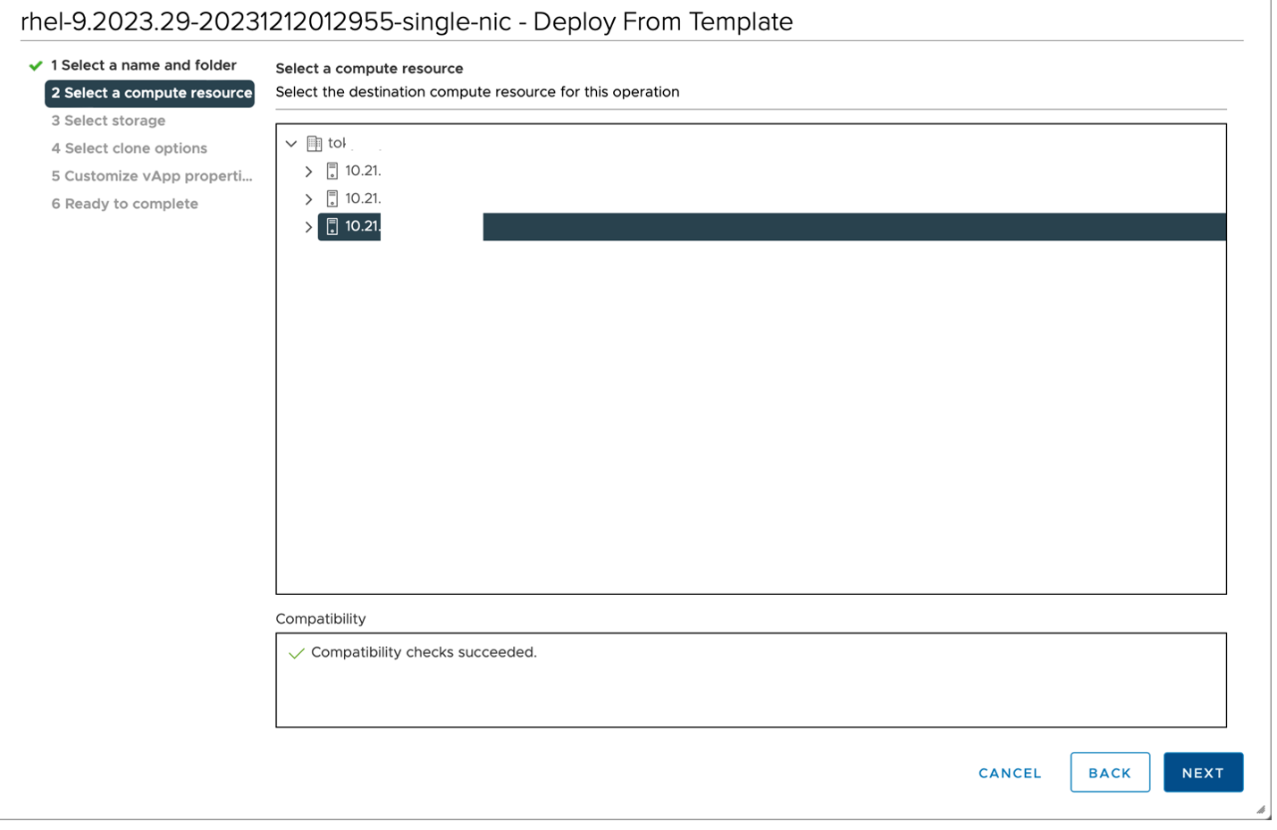
Figure: Select a compute resource page
Step 4: Select storage.
On the Select storage page, configure storage for the VM configuration and disk files and then click NEXT.
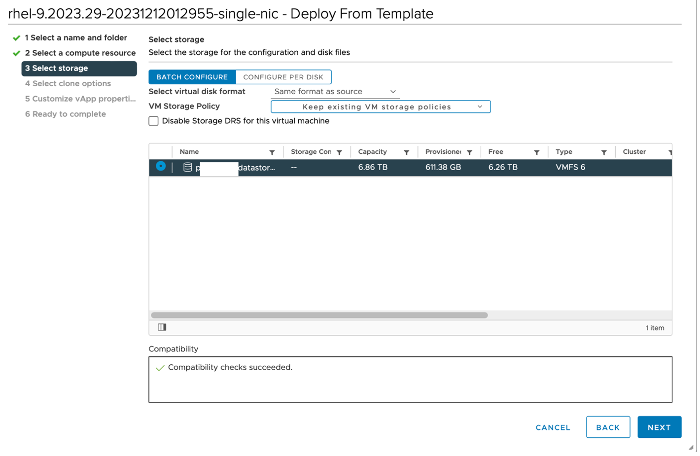
Figure: Select storage page
Step 5: Configure clone options.
On the Select clone options page, select the following options:
Customize this virtual machine’s hardwarePower on virtual machine after creation.
Then click NEXT.
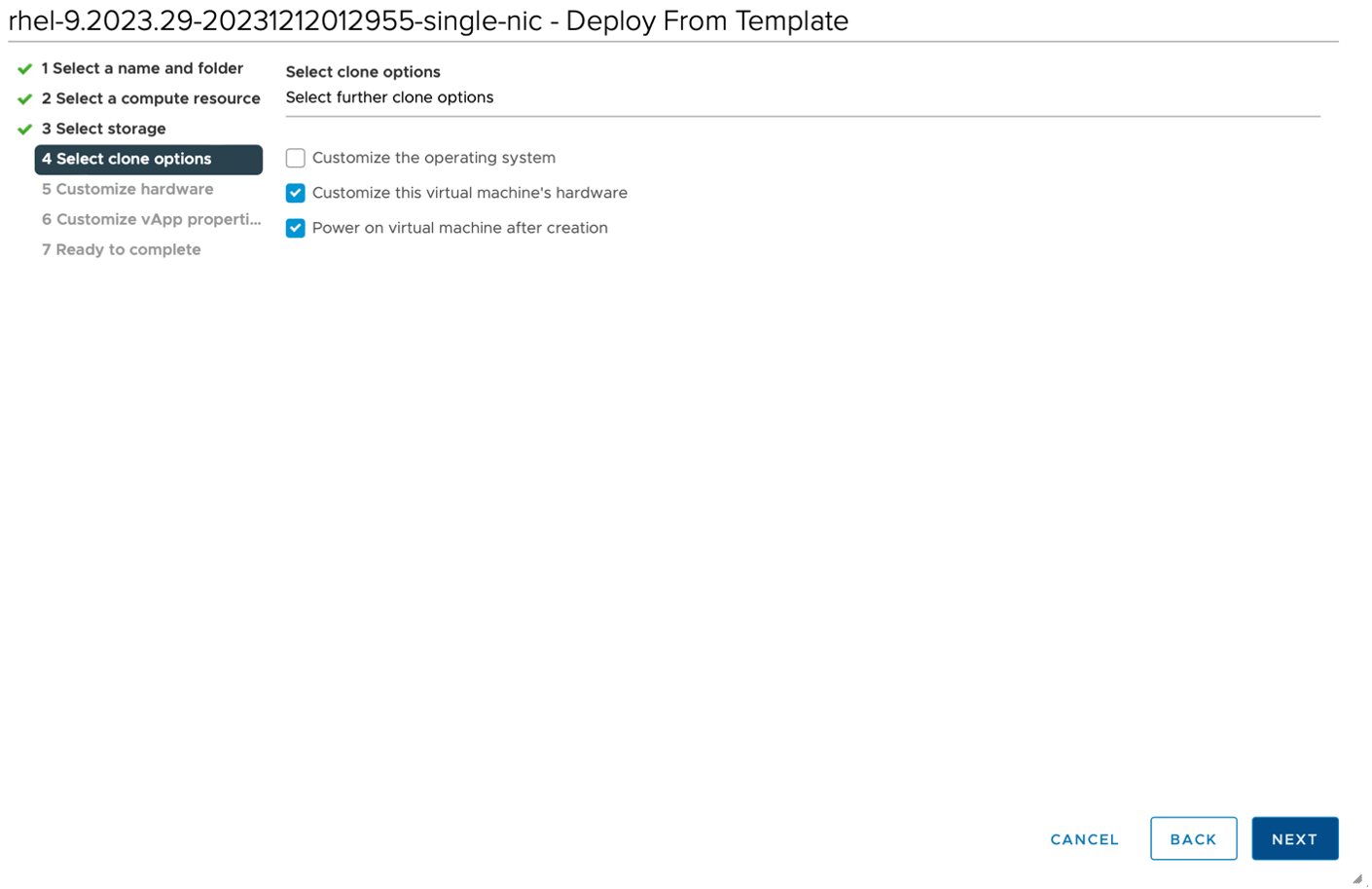
Figure: Configure clone options page
Step 6: Configure hardware.
-
On the
Customize hardwarepage, select theVirtual Hardwaretab and configure the following minimum configurations:-
CPU: 8
-
Memory (RAM): 32 GB
-
Hard disk: 80 GB
-
-
To configure an App Stack site, select the Network adapter with Internet access. Be sure to use only one Network adapter.
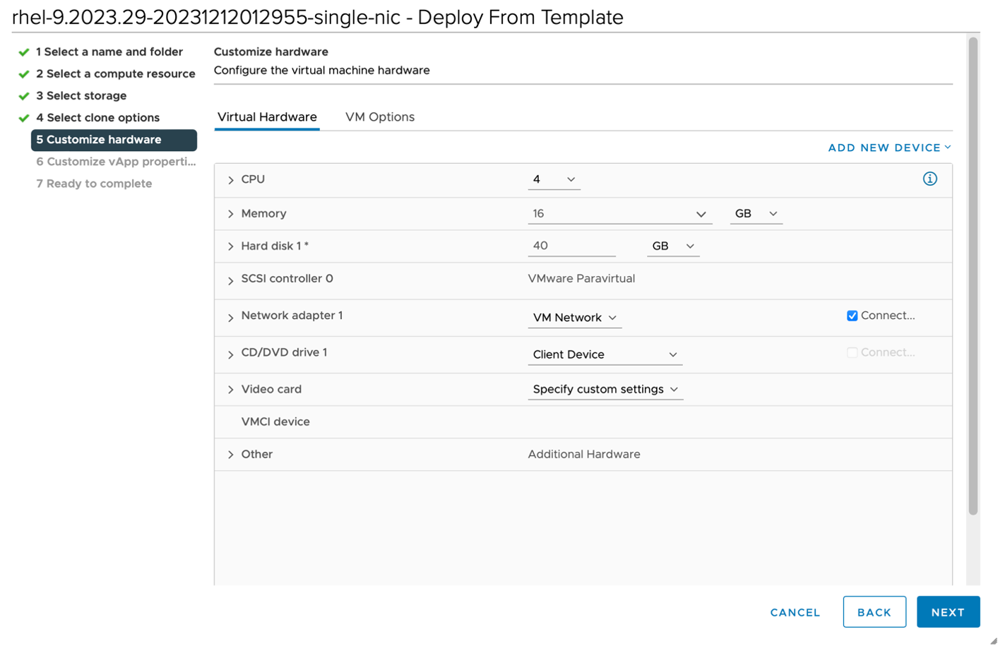
Figure: Customize hardware
-
You can configure a Secure Mesh site with two Network adapters, where:
- eth0 is dedicated for SLO (Site Local Outside) network with Internet access.
- eth1 is SLI (Site Local Inside) network with local network access. (Optional)
-
To add an additional network adapter, click
ADD NEW DEVICEand then clickNetwork Adapter.
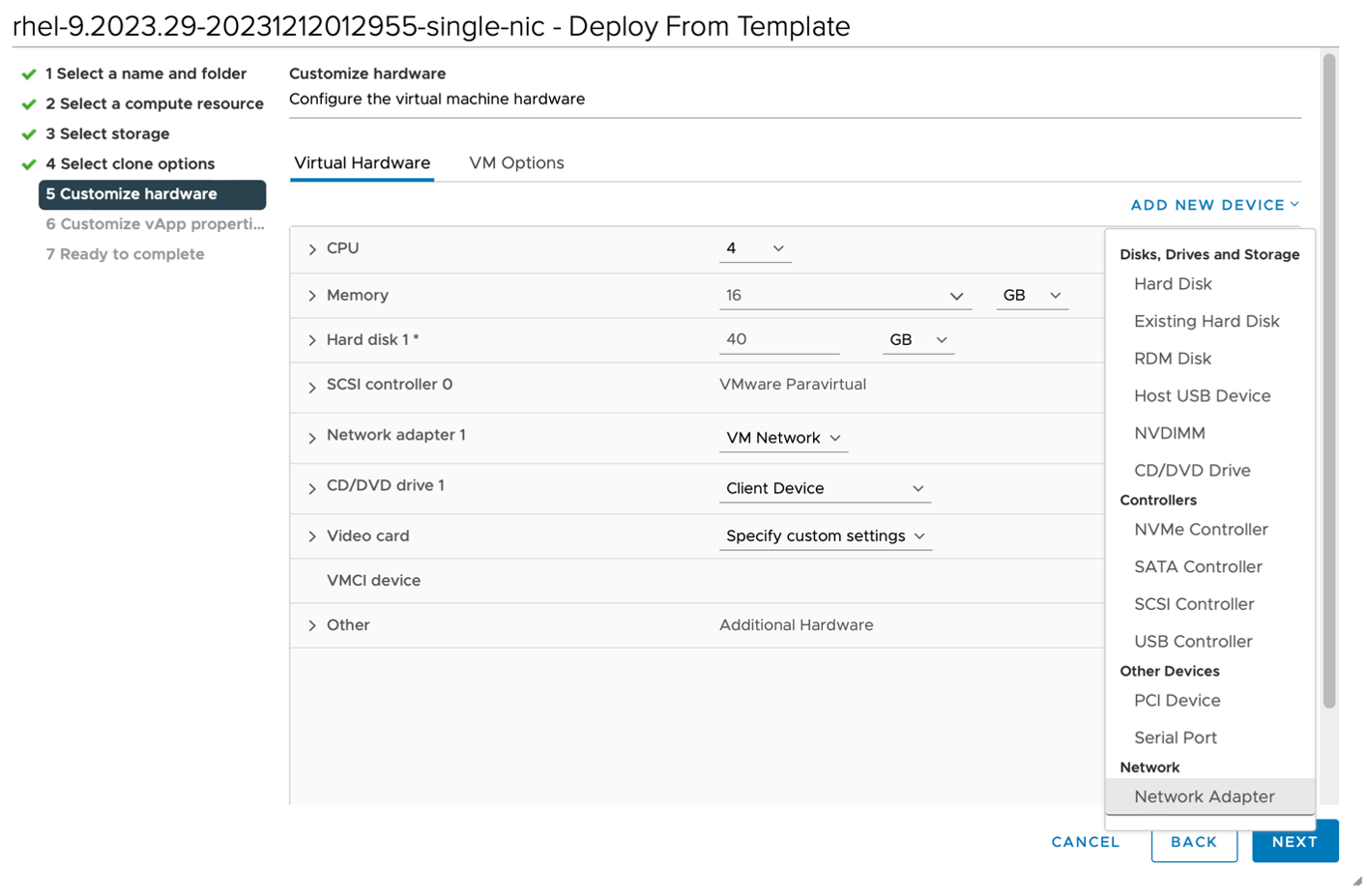
Figure: Add New Device
- Select the network adapter without Internet access as the SLI network for the new Network Adapter.
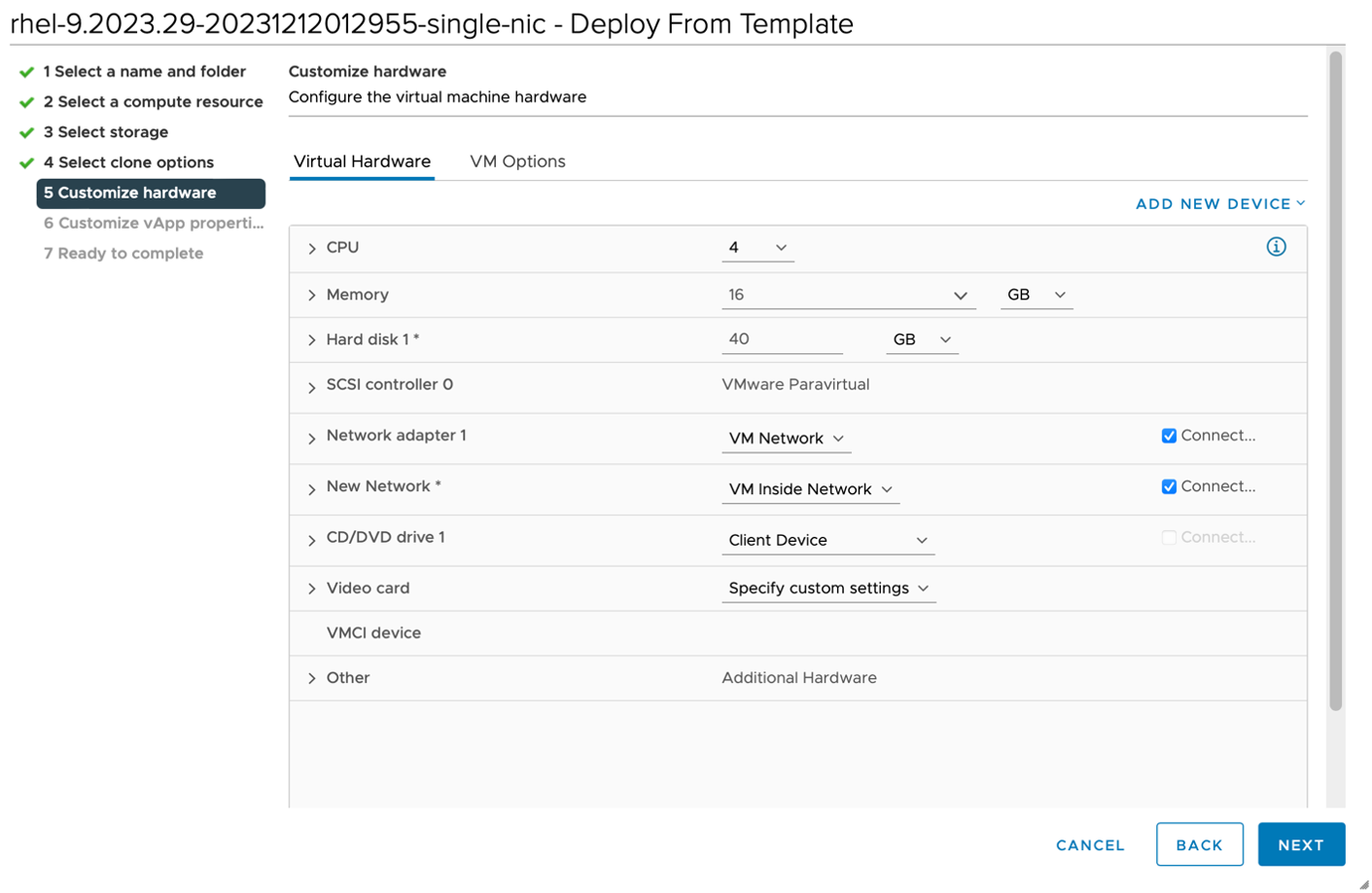
Figure: Add Network Adapter
- Click
NEXT.
Step 7: Customize vApp properties.
-
Hostname: Enter theHostnamefor this device. For example, entermaster-0. Ensure that host names are unique per cluster in case you install nodes for a multi-node site. -
Token: A site token is required for site generation. You must generate the token prior to using it in site creation. For information, see the Create Site Token section. -
Admin Password: You need this password to access Site CLI usingadminusername. The default password isVolterra123. -
Cluster Name: Set the Cluster name to match the provisioned Secure Mesh or App Stack site name in the Distributed Cloud Console. -
Name for outside network interface:Entereth0. -
DHCP support for outside network interface: Enteryes. If you want to configure static IP addresses, then enterno. -
Role for outside network interface: Enterpublic. By default, this is set topublicas the is used for egress traffic using SNAT. -
IP address/bitmask for network interface: This is empty by default. If you set DHCPno, then you can configure your static IP address here. For example,10.1.1.1/24. F5 recommends that you use a static IP for a site. -
Default gateway for outside network interface: This is empty by default. If you set DHCP tono, you can configure the default gateway for your network here. For example, 10.1.1.254. -
Route destination (destination network) for outside network interface: This is empty by default. If you set DHCP tono, you can configure the destination here. Because this is the default gateway, you can use 0.0.0.0/0. For specific setups, you can change the default destination. -
Primary DNS: This is empty by default. If you set DHCP tono, you can configure your DNS server here. For example, 8.8.8.8. -
Secondary DNS server - default: This is empty by default (received using DHCP). If you set DHCP tono, you can configure your secondary DNS server here. For example: 8.8.4.4. -
Registration URL: Set toves.volterra.ioby default. -
Certified Hardware: Select one of the following options.vmware-regular-nic-voltmesh: Single NIC or two NICs, where eth0 is dedicated for the SLO network and eth1 is for the SLI network. This certified hardware is required for a Secure Mesh Site. This is the default selection.vmware-voltstack-combo: Single NIC where eth0 is dedicated for the SLO network. This certified hardware is required for an App Stack Site.
-
Latitude. Enter theLatitude. You can also enter the Latitude during site registration in the Distributed Cloud Console. -
Longitude. Enter theLongitude. You can also enter the Longitude during site registration in the Distributed Cloud Console.
Click NEXT.
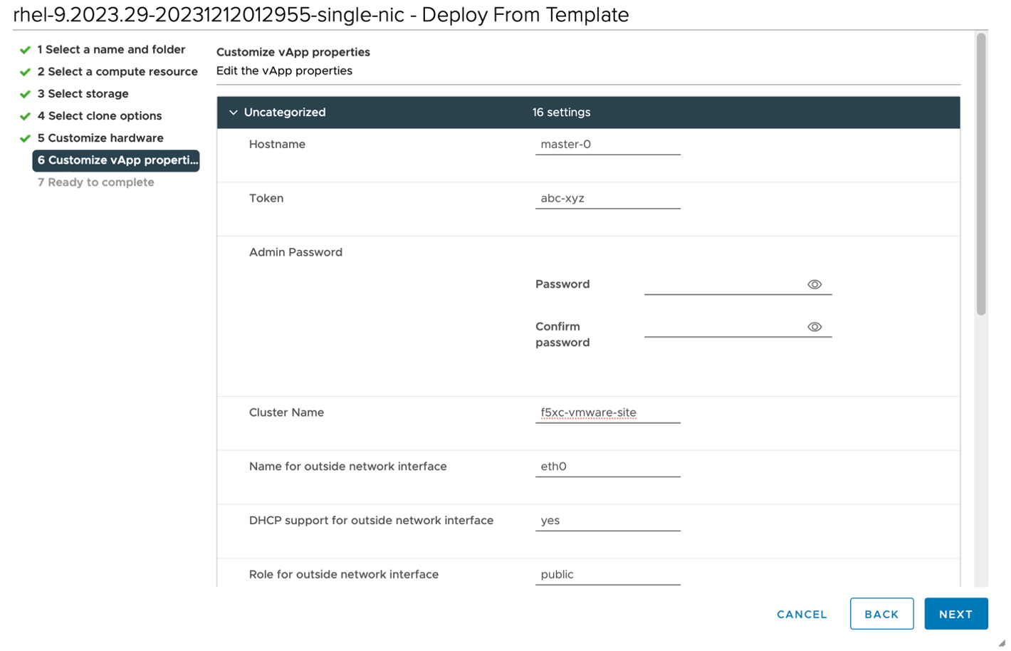
Figure: Customize vApp properties
Step 8: Create the VM.
On the Ready to complete page, verify the configuration and click FINISH to start the VM creation process.
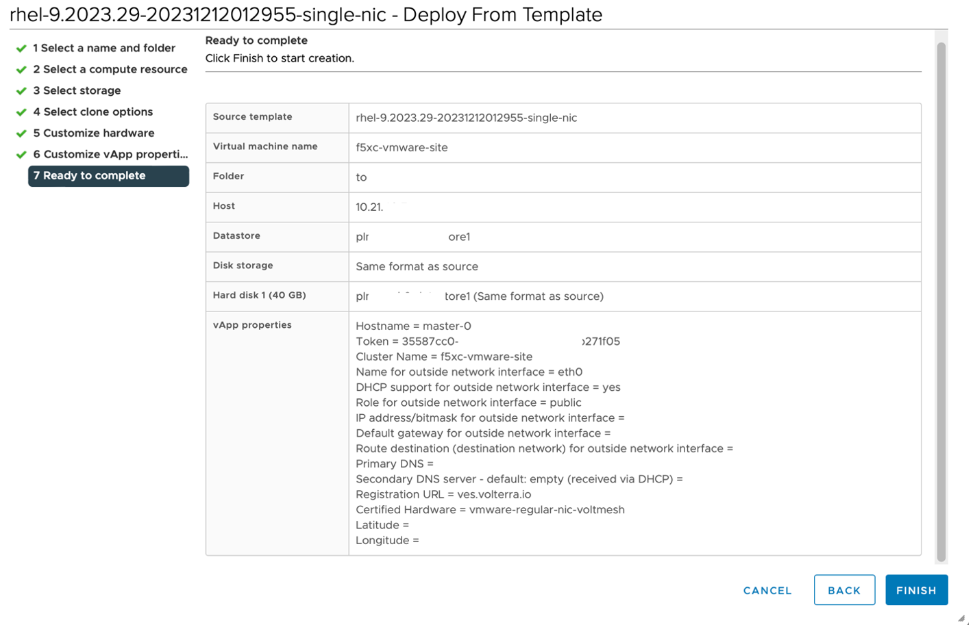
Figure: Ready to complete page
Important: The factory reset functionality is not supported. To update your site node, power off and then destroy it. Perform the same procedure as above to recreate a VM.
Important: After you create and register your site, you can access its local user interface (UI) to perform certain configuration and management functions. For more information, see Access Site Local User Interface. Access Site Local User Interface.
Register CE Site
After you install the F5 Distributed Cloud Services node, you must register it as a CE Site in the Distributed Cloud Console. For a multi-node CE Site, you must register each node.
Note: The USB allowlist is enabled by default. If you change a USB device, such as a keyboard after registration, the device will not function.
Register Multi-Node Site
Step 1: Navigate to the site registration page.
-
Log into Console.
-
Click
Multi-Cloud Network Connect. -
Click
Manage>Site Management>Registrations.
Step 2: Accept the registration requests.
Registration requests are displayed in the Pending Registrations tab.
-
Click
Acceptto accept the registration requests from themaster-0,master-1, andmaster-2nodes. The node names will differ. -
Enter the same values for the following parameters for all the registration requests:
-
In the
Cluster namefield, enter a name for the cluster. Ensure that all master nodes have the same name. -
In the
Cluster sizefield, enter3. Ensure that all master nodes have the same cluster size.
-
-
Enter all mandatory fields marked with the asterisk (
*) character. -
Click
Save and Exit.
Step 3: Check site status and health.
It may take a few minutes for the site health and connectivity score information to update.
-
Click
Overview>Infrastructure>Sites. -
Click on your site name. The
Dashboardtab appears, along with many other tabs to inspect your site. -
Click the
Site Statustab to verify the following:-
The
Update Statusfield has aSuccessfulvalue for theF5 OS Statussection. -
The
Update Statusfield has aSuccessfulvalue for theF5 Software Statussection. -
The
Tunnel statusandControl Planefields under theRE Connectivitysection haveupvalues.
-
Note: The factory reset functionality is not supported. To update a site node, power off and then destroy it. Perform the same procedure as above to recreate a virtual machine (VM).
Register Single-Node Site
Step 1: Navigate to the site registration page.
-
Log into Console.
-
Click
Multi-Cloud Network Connect. -
Click
Manage>Site Management>Registrations.
Step 2: Accept the registration requests.
Registration requests are displayed in the Pending Registrations tab.
-
Click
Acceptto accept the registration request for the node. -
In the form that appears, enter all mandatory fields marked with the asterisk (
*) character. -
Enter latitude and longitude values if you did not previously.
-
Enter other configuration information, if needed.
-
Click
Save and Exit.
Step 3: Check site status and health.
It may take a few minutes for the site health and connectivity score information to update.
-
Click
Overview>Infrastructure>Sites. -
Click on your site name. The
Dashboardtab appears, along with many other tabs to inspect your site. -
Click the
Site Statustab to verify the following:-
The
Update Statusfield has aSuccessfulvalue for theF5 OS Statussection. -
The
Update Statusfield has aSuccessfulvalue for theF5 Software Statussection. -
The
Tunnel statusandControl Planefields under theRE Connectivitysection haveupvalues.
-
Note: The factory reset functionality is not supported. To update a site node, power off and then destroy it. Perform the same procedure as above to recreate a virtual machine (VM).