Create KVM Site
Objective
Important: This is a legacy workflow for deploying Customer Edge (CE) Sites and is not recommended to use. A new workflow for deploying Customer Edge (CE) Sites has been introduced and is now Generally Available (GA). F5 recommends that you use the new Secure Mesh Site (v2) workflow for all Customer Edge deployments. You can find this workflow here.
F5® Distributed Cloud Services support site deployment for a Kernel-based Virtual Machine (KVM) with libvirt. This document explains how to perform Distributed Cloud Services node installation on a server using a KVM with libvirt and to perform site registration on F5® Distributed Cloud Console (Console).
The following is a sample topology for the hypervisor and guest machine setup. The sample shows three guest virtual machines installed with F5 Distributed Cloud Services Site software running on the hypervisor host.
Only one virtual machine is required. However, if you require a high-availability (HA) deployment, you must deploy three VMs.
Important: Each virtual machine (VM) must have the same cluster name and a unique hostname.
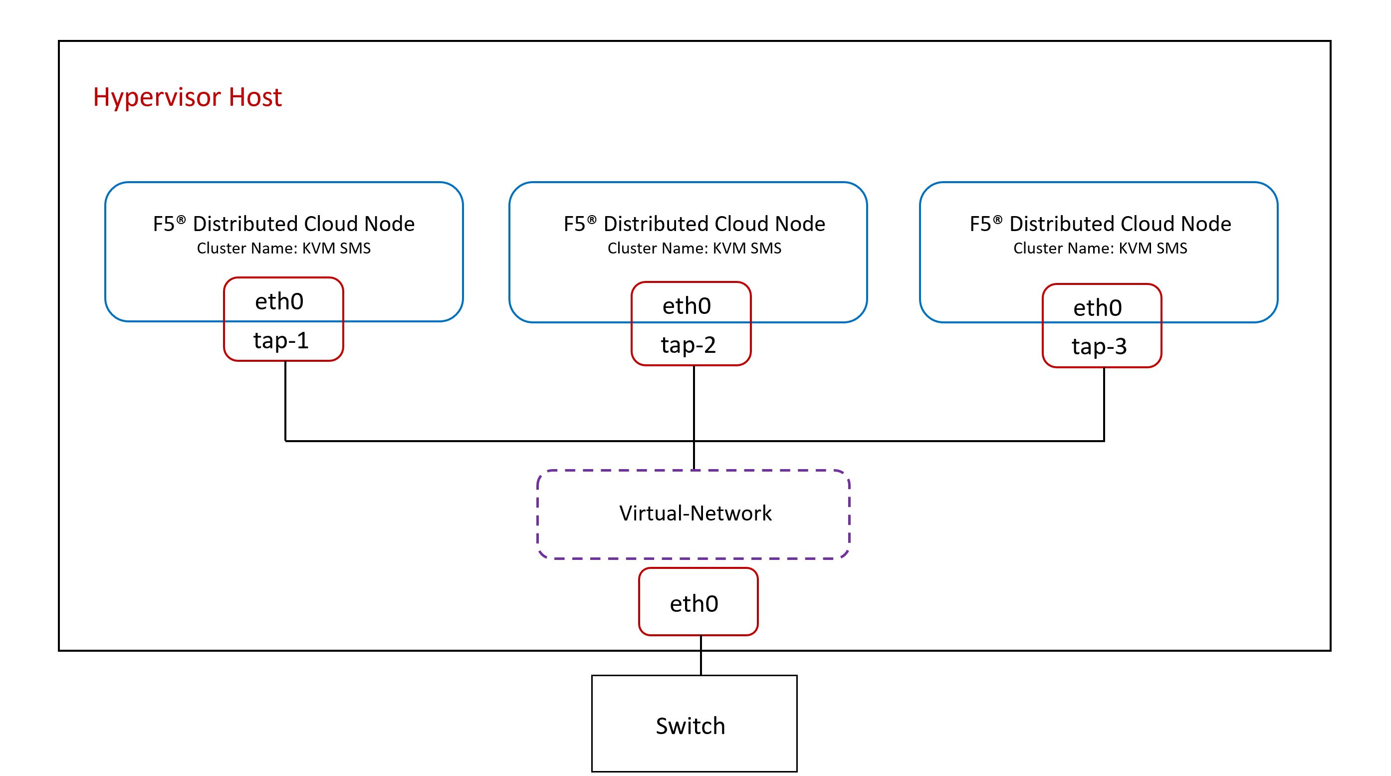
Figure: Hypervisor Topology
There are three ways to deploy a Secure Mesh Site using KVM. Review the Prerequisites section and then see the following sections for more information:
- Deploy a Secure Mesh Site with an ISO Image
- Deploy a Secure Mesh Site with a QCOW2 Image
- Deploy a Secure Mesh Site Using Terraform Automation (QCOW2)
Prerequisites
-
A Distributed Cloud Services Account. If you do not have an account, see Getting Started with Console.
-
A server supporting hardware virtualization. The KVM only works if the server CPU has hardware virtualization support (Intel VT or AMD-V).
-
KVM installed and running.
-
At least one interface with Internet access. Distributed Cloud Services Node Zero-Touch Provisioning requires Internet connectivity to the Distributed Cloud Console.
-
A KVM image file. Click here to download.
-
Resources required per node: Minimum 8 vCPUs and 32 GB RAM. 80 GB is the minimum amount required for storage. However, to deploy an F5 Distributed Cloud App Stack Site, F5 recommends a minimum of 100 GB of storage. For a full listing of the resources required, see the Customer Edge Site Sizing Reference guide. All the nodes in a given CE Site should have the same resources regarding the compute, memory, and disk storage. When deploying in cloud environments, these nodes should use the same instance flavor.
-
Allow traffic from and to the Distributed Cloud public IP addresses to your network and allowlist related domain names. See F5 Customer Edge IP Address and Domain Reference for Firewall or Proxy Settings guide for the list of IP addresses and domain names.
-
To ensure intra-cluster communication checks, you must enable Internet Control Message Protocol (ICMP) between the Customer Edge (CE) nodes on the Site Local Outside (SLO) interfaces.
-
The
--cloud-initoption was introduced invirt-installversion 3.0.0. Ensure you update your system to this version.
Important: After you deploy the CE Site, the IP address for the SLO interface cannot be changed. Also, the MAC address cannot be changed.
- By proceeding with the installation, download and/or access and use, as applicable, of the Distributed Cloud Services software, and/or Distributed Cloud Services platform, you acknowledge that you have read, understand, and agree to be bound by this agreement.
Note: The following procedures are based on
virt-installpackages. You can also usevirt-managerusing the same parameters.
Create Secure Mesh Site
Before you deploy a single-node or multi-node site (for HA) on KVM, you must create a site in the F5 Distributed Cloud Console. For information, see Create Secure Mesh Site.
When you create your site, make sure to use the following settings:
Name: The cluster name. For HA deployments, each node must have the same cluster name.Hostname: A unique hostname for each site. To configure an HA deployment, each site must have a different hostname.Generic Server Certified Hardware: For single interface deployments, set tokvm-voltmesh. For two-interface (OUTSIDE, INSIDE) deployments, set tokvm-regular-nic-voltmesh.
Important: When you create a Secure Mesh Site in the Distributed Cloud Console, you must also create a site token. You use that same site token later when you deploy the Secure Mesh Site on KVM.
Deploy a Secure Mesh Site with an ISO Image
To deploy a Secure Mesh Site from the ISO image you downloaded from F5, you must complete the following high-level steps:
- Spawn a virtual machine (VM) to host the Secure Mesh Site.
- Install the Red Hat Linux 9 (RHEL9) operating system (OS) on the VM.
- Provision Distributed Cloud configuration.
- Register the site and complete Distributed Cloud configuration.
Create Node VM
To spawn a VM from an ISO image that you downloaded from F5, enter the following commands.
% qemu-img create /var/lib/libvirt/images/kvm-sms.qcow2 80G
% virt-install \    --name kvm-sms \    --vcpus 8 \    --memory 32768 \    --network network=default,model=virtio \    --disk path=/var/lib/libvirt/images/kvm-sms.qcow2,bus=virtio,cache=none,size=80 \    --cdrom /var/lib/libvirt/images/RHEL-9.2024.11-Installer.iso \    --accelerate \    --os-variant rhl9 \    --virt-type kvm \    --noautoconsole \    --graphics vnc
Depending on how you want to deploy your site, you can also consider the following actions:
- To deploy a site with two interfaces (
OUTSIDE,INSIDE), add another network section. - To build an HA cluster, spawn two additional VMs.
Install the RHEL9 Operating System
The following steps explain how to install the RHEL9 OS on your VM with the ISO image that you downloaded from F5.
Step 1: Install RHEL9.
Connect to a VNC console and complete the following steps to select the language and disk. To connect, type: virsh vncdisplay kvm-sms.
For KVM deployments, you must select VDA as the disk type. You specify disk size when you spawn the VM.
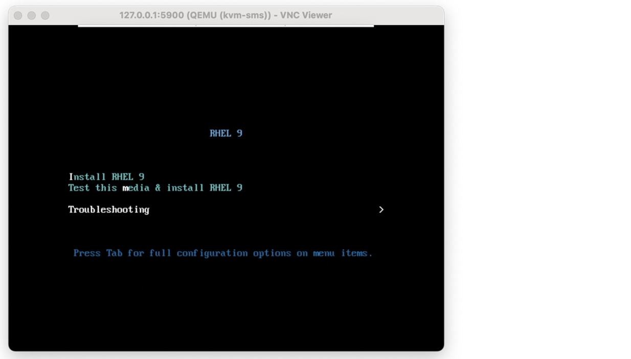
Figure: VNC console
Select the language you want to use.
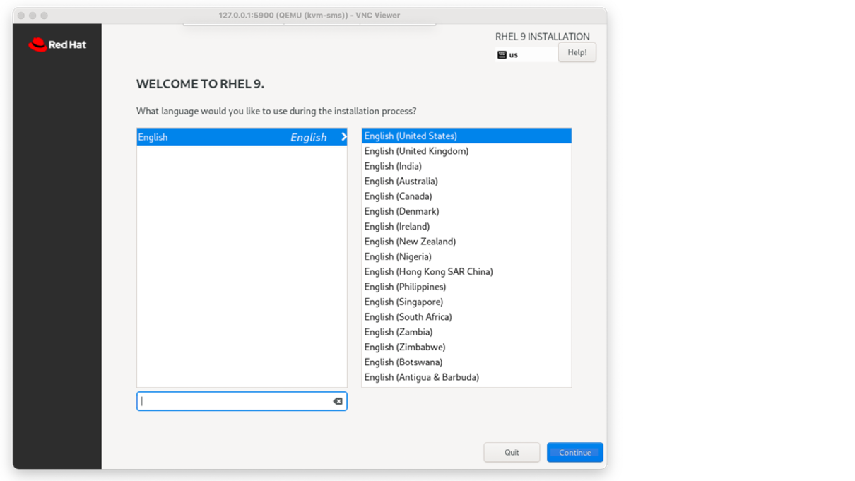
Figure: Language selection
Select the disk where you want to deploy the RHEL9.
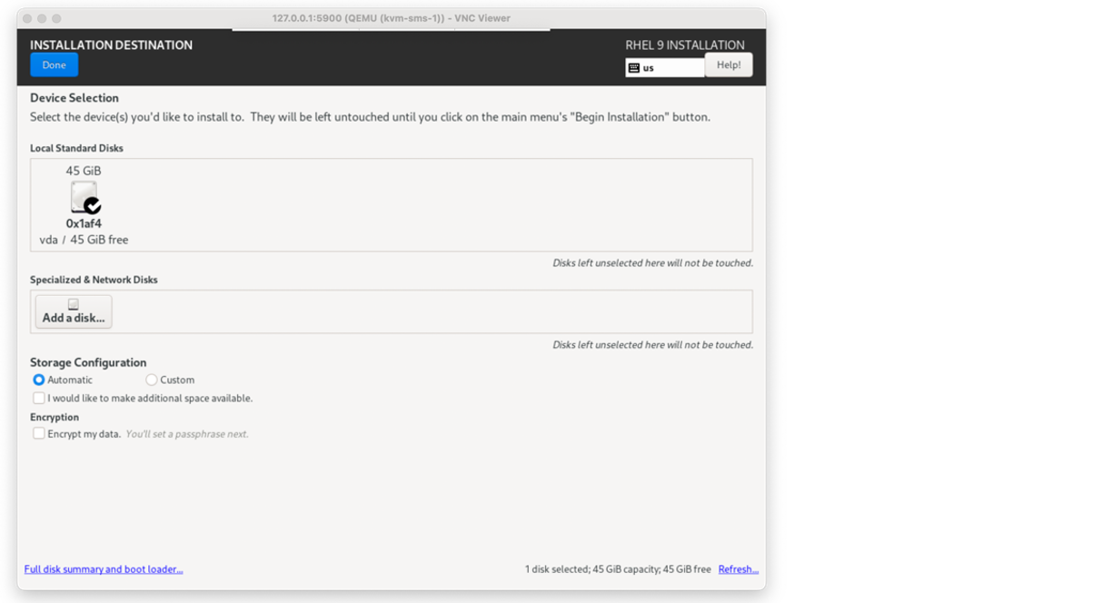
Figure: Disk selection
Review your configuration settings.
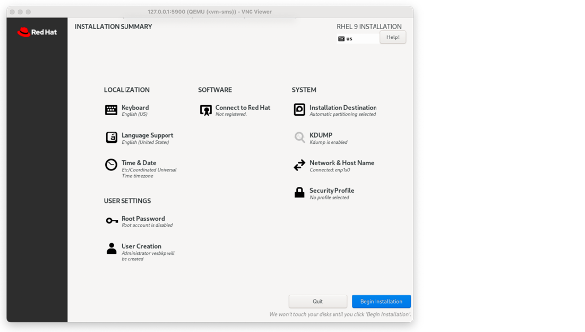
Figure: Configuration settings
Complete the installation.
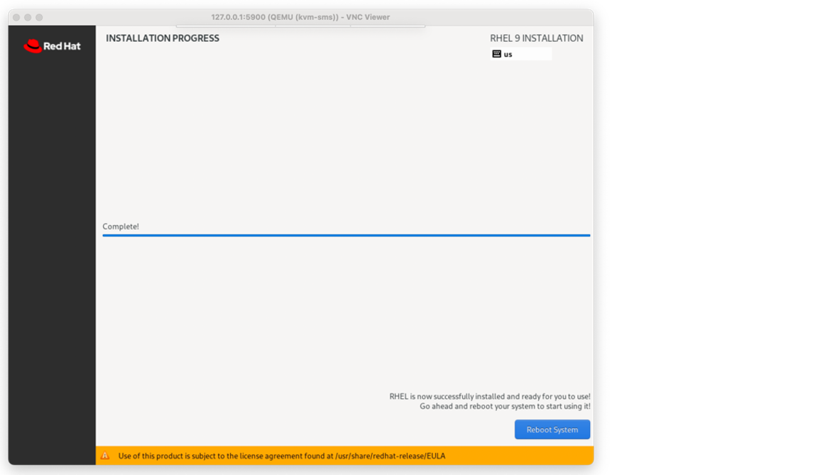
Figure: Installation progress
Step 2: Restart the VM.
After the VM reboots, you must restart the VM.
To restart the VM, type: virsh start kvm-sms.
Important: If you are configuring an HA deployment, you must restart all nodes in the HA cluster.
Note: After you reboot the VM, it takes a few minutes to prepare the site shell. Wait a few minutes before you start provisioning Distributed Cloud configuration.
Provision Distributed Cloud Configuration
Step 1: Connect to the VM.
Do one of the following to connect to the VM:
To connect to the VM through a console window:
- Open a console window and type
virsh console kvm-sms: - When prompted, enter the following information:
- Username:
admin - Default password:
Volterra123
- Username:
To connect to the VM using SSH:
- From a command prompt, type
virsh domifaddr kvm-sms. - Type
ssh admin@192.168.122.9.
Step 2: Change the VM admin password.
The first time you connect to the VM, you are prompted to change the KVM Secure Mesh Site admin password.
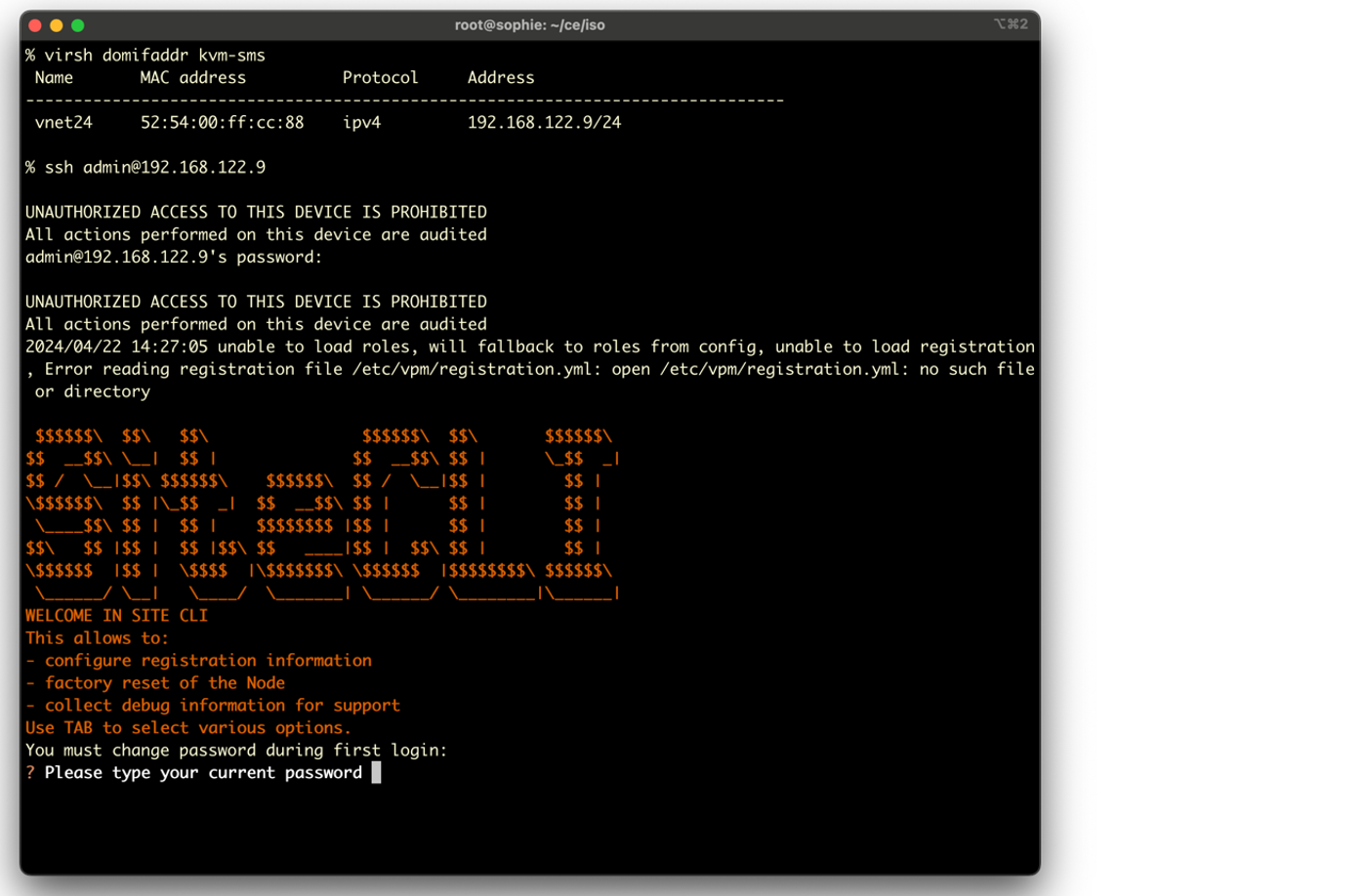
Figure: Change password
Step 3: Configure KVM Secure Mesh Site network.
To configure the KVM Secure Mesh Site network, enter the required configuration information.
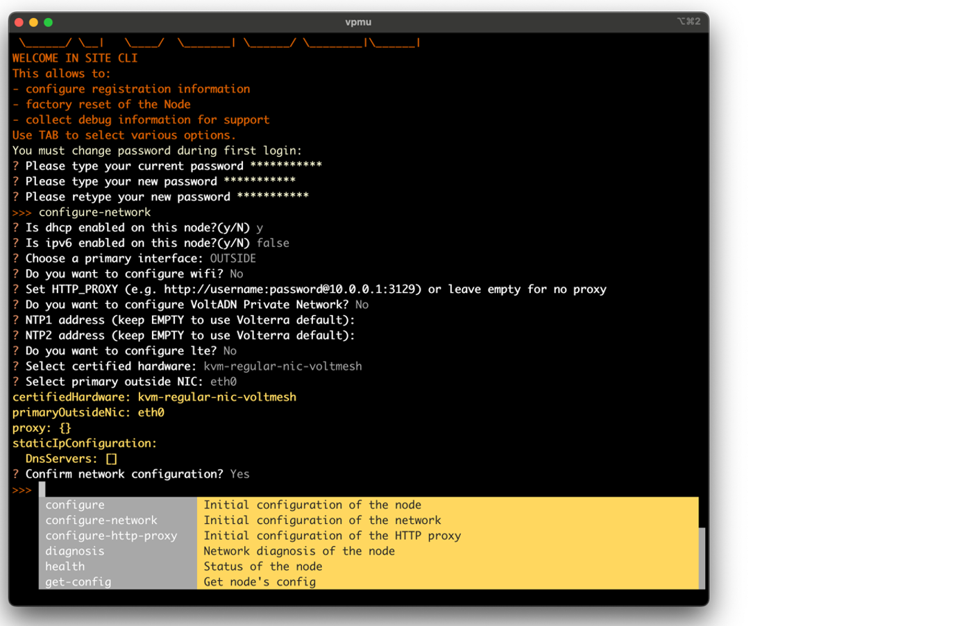
Figure: Configuration information
After you provide the required network configuration information, the system automatically reboots.
Step 4: Configure KVM Secure Mesh Site deployment parameters.
Configure KVM Secure Mesh Site deployment parameters.
Important: You must use the same
cluster name,hostnameandcertified hardwareparameter values and the same site token that you used when you added the Secure Mesh Site in the Distributed Cloud Console.
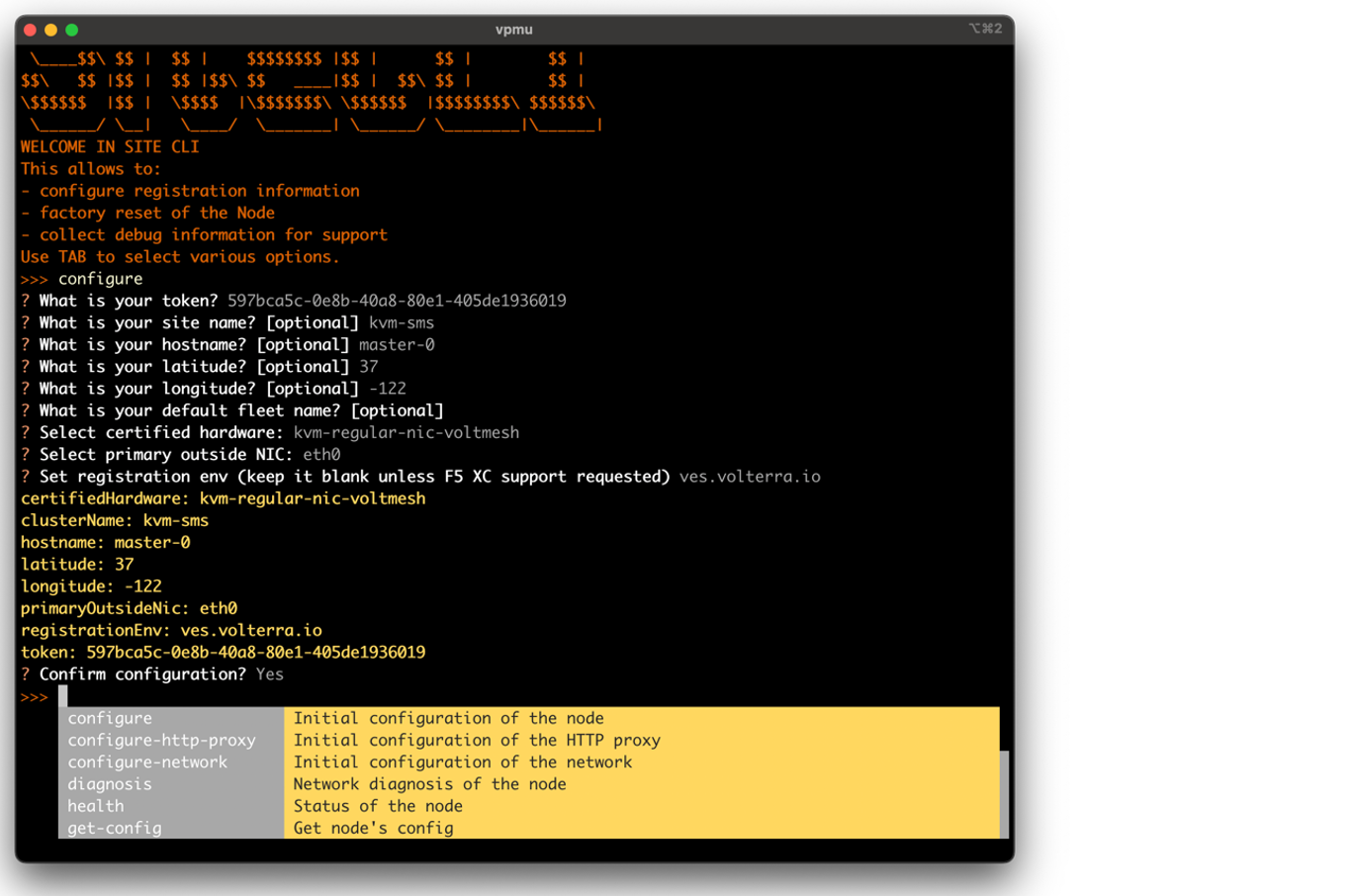
Figure: KVM Secure Mesh Site deployment parameters
Step 5: Register the site and complete Distributed Cloud configuration.
After you spawn the VM and deploy a Secure Mesh Site, see Register CE Site to finish Distributed Cloud configuration.
Deploy a Secure Mesh Site with a QCOW2 Image
To deploy a Secure Mesh Site from a QCOW2 image, you must complete the following high-level steps:
- Spawn a VM to host the Secure Mesh Site.
- Register the site and complete Distributed Cloud configuration.
Templates for building files can be found under these links. This repository is publicly available.
- https://github.com/f5devcentral/f5-xc-kvm-ce/blob/main/terraform/cloudinit/user-data.tpl
- https://github.com/f5devcentral/f5-xc-kvm-ce/blob/main/terraform/cloudinit/meta-data.tpl
Before you begin, you must edit the following variables in user-data.tpl to match your entries in your Secure Mesh Site:
cluster-namehost-namelatitudeandlongitudexc-environment-api-endpoint: You must set this toves.volterra.iocertified-hw: For single interface deployments, replacecertified-hwwithkvm-voltmesh. For two-interface (OUTSIDE, INSIDE) deployments, replacecertified-hwwithkvm-regular-nic-voltmesh.
Step 1: Spawn a VM to host the Secure Mesh Site.
To spawn a VM from a QCOW2 image, enter the following commands.
% genisoimage -output cloud-init.iso -volid cidata -joliet -rock user-data meta-data
% cp rhel-9.2024.6-20240216073447.qcow2 /var/lib/libvirt/images/kvm-sms.qcow2
% virt-install \    --name kvm-sms \    --vcpus 8 \    --memory 32768 \    --network network=default,model=virtio \    --disk /var/lib/libvirt/images/kvm-sms.qcow2,device=disk,bus=virtio,format=qcow2 \    --disk cloud-init.iso,device=cdrom \    --import \    --os-variant rhl9 \    --virt-type kvm \    --accelerate \    --noautoconsole \    --graphics none
Step 2: Register the site and complete Distributed Cloud configuration.
After you spawn the VM and deploy a Secure Mesh Site, see Register CE Site to finish Distributed Cloud configuration.
Deploy a Secure Mesh Site Using Terraform Automation (QCOW2)
This is the recommended way to deploy a KVM Secure Mesh Site. View the README file for deployment information: https://github.com/f5devcentral/f5-xc-kvm-ce.
The repository includes all automation needed to deploy a KVM Secure Site Mesh with one terraform apply command.
Register CE Site
After you install the F5 Distributed Cloud Services node, you must register it as a CE Site in the Distributed Cloud Console. For a multi-node CE Site, you must register each node.
Note: The USB allowlist is enabled by default. If you change a USB device, such as a keyboard after registration, the device will not function.
Register Multi-Node Site
Step 1: Navigate to the site registration page.
-
Log into Console.
-
Click
Multi-Cloud Network Connect. -
Click
Manage>Site Management>Registrations.
Step 2: Accept the registration requests.
Registration requests are displayed in the Pending Registrations tab.
-
Click
Acceptto accept the registration requests from themaster-0,master-1, andmaster-2nodes. The node names will differ. -
Enter the same values for the following parameters for all the registration requests:
-
In the
Cluster namefield, enter a name for the cluster. Ensure that all master nodes have the same name. -
In the
Cluster sizefield, enter3. Ensure that all master nodes have the same cluster size.
-
-
Enter all mandatory fields marked with the asterisk (
*) character. -
Click
Save and Exit.
Step 3: Check site status and health.
It may take a few minutes for the site health and connectivity score information to update.
-
Click
Overview>Infrastructure>Sites. -
Click on your site name. The
Dashboardtab appears, along with many other tabs to inspect your site. -
Click the
Site Statustab to verify the following:-
The
Update Statusfield has aSuccessfulvalue for theF5 OS Statussection. -
The
Update Statusfield has aSuccessfulvalue for theF5 Software Statussection. -
The
Tunnel statusandControl Planefields under theRE Connectivitysection haveupvalues.
-
Note: The factory reset functionality is not supported. To update a site node, power off and then destroy it. Perform the same procedure as above to recreate a virtual machine (VM). After you create and register your site, you can access the local user interface (UI) to perform certain configuration and management functions. For more information, see the Access Site Local User Interface guide.
Register Single-Node Site
Step 1: Navigate to the site registration page.
-
Log into Console.
-
Click
Multi-Cloud Network Connect. -
Click
Manage>Site Management>Registrations.
Step 2: Accept the registration requests.
Registration requests are displayed in the Pending Registrations tab.
-
Click
Acceptto accept the registration request for the node. -
In the form that appears, enter all mandatory fields marked with the asterisk (
*) character. -
Enter latitude and longitude values if you did not previously.
-
Enter other configuration information, if needed.
-
Click
Save and Exit.
Step 3: Check site status and health.
It may take a few minutes for the site health and connectivity score information to update.
-
Click
Overview>Infrastructure>Sites. -
Click on your site name. The
Dashboardtab appears, along with many other tabs to inspect your site. -
Click the
Site Statustab to verify the following:-
The
Update Statusfield has aSuccessfulvalue for theF5 OS Statussection. -
The
Update Statusfield has aSuccessfulvalue for theF5 Software Statussection. -
The
Tunnel statusandControl Planefields under theRE Connectivitysection haveupvalues.
-
Note: The factory reset functionality is not supported. To update a site node, power off and then destroy it. Perform the same procedure as above to recreate a virtual machine (VM). After you create and register your site, you can access the local user interface (UI) to perform certain configuration and management functions. For more information, see the Access Site Local User Interface guide.
Access CE Site Local UI
After you create and register your site, you can access its local user interface (UI) to perform certain configuration and management functions. For more information, see Access Site Local User Interface.
Concepts
- System Overview
- Core Concepts
- Networking
- F5 Distributed Cloud - Customer Edge
- F5 Distributed Cloud Site
On this page:
- Objective
- Prerequisites
- Create Secure Mesh Site
- Deploy a Secure Mesh Site with an ISO Image
- Create Node VM
- Install the RHEL9 Operating System
- Provision Distributed Cloud Configuration
- Deploy a Secure Mesh Site with a QCOW2 Image
- Deploy a Secure Mesh Site Using Terraform Automation (QCOW2)
- Register CE Site
- Register Multi-Node Site
- Register Single-Node Site
- Access CE Site Local UI
- Concepts