Create GCP Site (Orchestrated)
Objective
Important: F5 highly recommends you use the new Secure Mesh Site (v2) workflow for AWS, Azure, and GCP using this guide. This workflow is only recommended when you want F5 Distributed Cloud Services to orchestrate cloud resources needed for Customer Edge (CE) Site deployments in public clouds.
This guide provides instructions on how to create and deploy a Virtual Private Cloud (VPC) F5 Distributed Cloud Site in Google Cloud Platform (GCP).
You can deploy a VPC site if the workload you want to secure, connect, or load balance is present on or will be deployed in the same VPC. You may also choose to deploy a VPC site if you want to use the F5® managed Kubernetes offering by creating an App Stack site.
Deployment Environments
F5® Distributed Cloud Services supports GCP VPC site creation in both greenfield and brownfield environments. In a greenfield environment, Distributed Cloud Services can automate the creation of VPC networks, subnets, firewall rules, routes, and other networking features. In a brownfield environment, you can choose existing resources from your VPC or choose to create new resources using the site creation wizard.
Customer Edge Node Clustering
GCP VPC sites can be deployed as a single node or as a three-node site. These nodes host the control processes, data plane processes, and the IPsec connections to the Regional Edges (REs). For production deployments, F5 recommends a three-node site as it provides high availability and capacity for L7 features, like load balancing, WAAP, and more.
Important: Worker nodes are not currently supported on any type of GCP VPC site.
GCP VPC Site Deployment Modes
A site can be deployed in three different modes, as explained below. For a generic network topology of a site, see Network Topology of a Site.
Ingress Gateway (One Interface): This mode provides discovery of services and endpoints reachable from this subnet and delivers it to any other site in the customer tenant. The site can provide TCP or HTTP load balancing and L7 security services for the apps that it discovers on the VPC. This mode can be used for application delivery or IP address overlap use cases, but as it functions only as an ingress gateway, it cannot provide L3 connectivity to networks on other sites in the tenant. This mode also provides Secure Kubernetes Gateway functionality to Kubernetes clusters deployed on the same VPC.
A three-node deployment diagram is shown below.
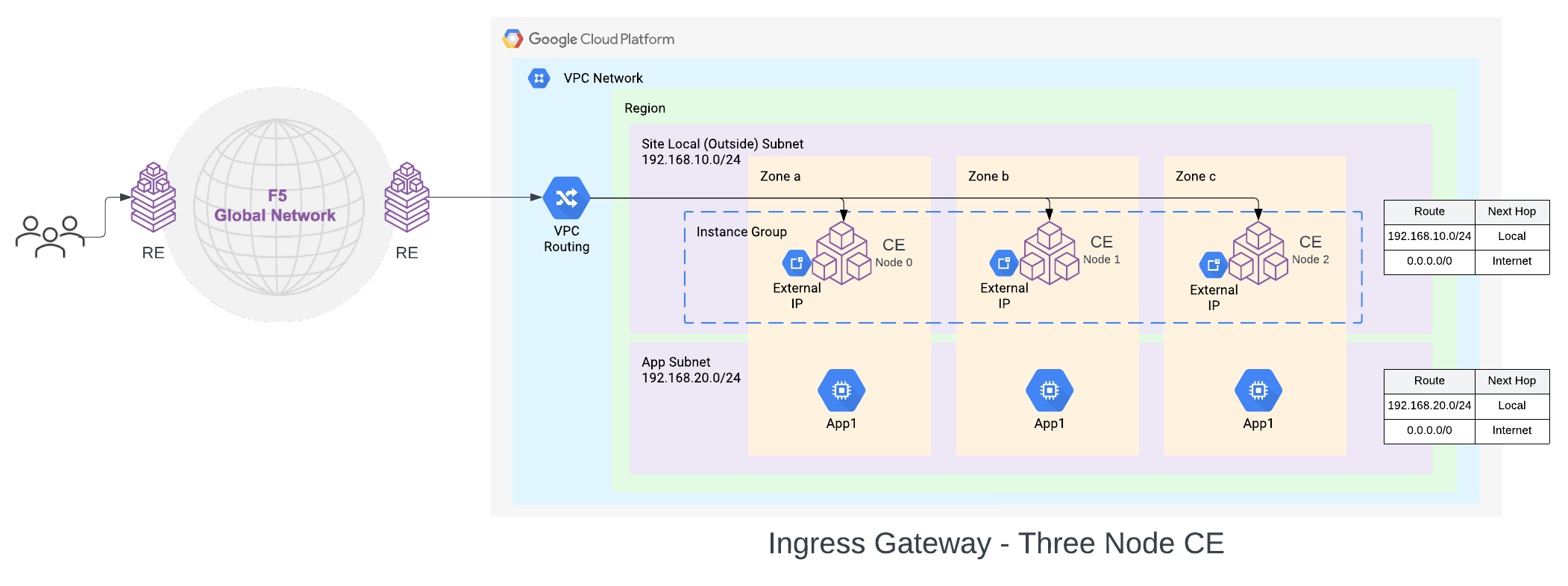
Figure: GCP VPC Site Deployment - Ingress Gateway (One Interface)
In this deployment mode, the CE node is attached to a single Subnet called the Site Local Outside (SLO), per GCP Zone in a VPC network. For a three-node cluster, the nodes will be distributed across three GCP zones. The default route associated with SLO must point to the Internet Gateway (IGW). This way the CE can reach the Internet and open the IPsec connections to the Regional Edges (REs).
The default configuration is to use an Internet Gateway for this, but Cloud NAT Gateway is also supported as an egress gateway option. The workloads can be deployed on a private subnet with a default route pointing to the Cloud NAT Gateway or on a public subnet with a default route pointing to the Internet Gateway. These subnets and routes are not auto-created.
Ingress/Egress Gateway (Two Interfaces): In this mode, the CE functions as a default gateway for the VPC network. This way, it can provide egress connectivity to the internet and L3 connectivity from the instances and subnets on the VPC network to subnets on other sites if a global network is configured. It can also provide the load balancing, Secure Kubernetes Gateway, and other L7 security features, like ingress gateway mode.
A three-node deployment diagram is shown below.
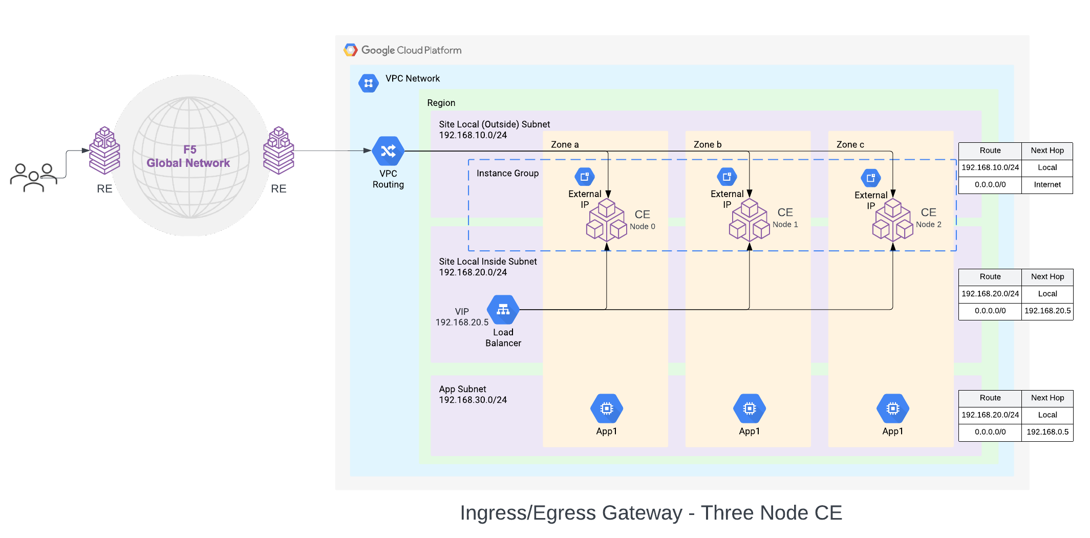
Figure: GCP VPC Site Deployment - Ingress/Egress Gateway (Two Interfaces)
In this mode, the CE node is attached to two interfaces on two different subnets, on two VPC networks. One subnet is labeled as Site Local Outside (SLO), and the other as Site Local Inside (SLI). The default route on the SLO VPC network points to the IGW as the default gateway (Cloud NAT gateway is also supported). This provides Internet connectivity to the CE nodes. The default route on the SLI VPC network points to the SLI interface of the CE node or the internal TCP passthrough Network Load balancer for CE SLI IP addresses, in case of multi-node CE site.
F5® Distributed Cloud App Stack Cluster (App Stack) (One Interface): This deployment mode must be used if you want to use the site as an F5-managed Kubernetes site to host your applications. This site mode also provides Secure Kubernetes Gateway for the applications deployed on it by discovering the services, providing load balancing and L7 security features, like WAAP, Bot Detection, DDoS protection, and more.
The deployment and configuration of this site is identical to the Ingress Gateway (One Interface) Site. The difference with this deployment is the certified hardware type being gcp-byol-voltstack-combo. This configures and deploys an instance type that allows the site to have Kubernetes pods or VMs deployed on the site using Kubernetes APIs via managed K8s or virtual K8s endpoints.
Site Status Descriptions
These descriptions provide information for the various stages of site deployment in Distributed Cloud Console. They also provide information to help you troubleshoot errors that may occur during the deployment and registration stages.
PLANNING: Site resources are being planned for creation.
PLAN_INIT_ERRORED: Planning of site resources failed at init stage.
PLAN_ERRORED: Planning of site failed with errors.
PLAN_QUEUED: Planning of site resources queued to be implemented.
APPLIED: Site resources are created, and site is waiting to come online.
APPLY_ERRORED: Creation of site resources failed with errors.
APPLY_INIT_ERRORED: Creation of site resources failed with errors at initial stage.
APPLYING: Site creation is in progress.
APPLY_PLANNING: Site resources are being planned.
APPLY_PLAN_ERRORED: Planning of site failed with errors.
APPLY_QUEUED: Creation of site resources queued to be implemented.
DESTROYED: Site resources are destroyed and site is OFFLINE.
DESTROY_ERRORED: Destroying of site resources failed with errors.
DESTROYING: Destroying of site resources in progress.
DESTROY_QUEUED: Destroying of site resources queued to be destroyed.
GENERATED: Site Object created in F5 Distributed Cloud Console database as per configuration.
TIMED_OUT: Creation/Destroying of site resources is failed with a timeout.
ERRORED: Creation/Destroying of site resources is failed with errors.
PROVISIONING: Site resources are created and waiting for site to come online.
Prerequisites
General
-
A Distributed Cloud Services Account. If you do not have an account, see Getting Started with Console.
-
A GCP account. See Required Access Policies for permissions needed to deploy a site. To create a cloud credentials object, see Create Cloud Credentials.
Note: By proceeding with the installation, download and/or access and use, as applicable, of the Distributed Cloud Services software, and/or Distributed Cloud Services platform, you acknowledge that you have read, understand, and agree to be bound by this agreement.
- Resources required per node:
- vCPUs: Minimum 8 vCPUs.
- Memory: 32 GB RAM.
- Disk storage:
- Minimum 80 GB for Mesh site.
- Minimum 100 GB for App Stack site.
Note: For a full listing of the resources required, see the Customer Edge Site Sizing Reference guide. All the nodes in a given CE Site should have the same resources regarding the compute, memory, and disk storage. When deploying in cloud environments, these nodes should use the same instance flavor.
-
Instance type with Intel x86-based processor. ARM and Mac instances are not supported. Recommended instance types are:
- Medium: n2-standard-8/t2d-standard-8/a2-highgpu-2g
- Large: n2-standard-16/t2d-standard-16/a2-highgpu-4g
-
Allow traffic from and to the Distributed Cloud public IP addresses to your network and allowlist related domain names. See F5 Customer Edge IP Address and Domain Reference for Firewall or Proxy Settings guide for the list of IP addresses and domain names.
-
UDP port 6080 needs to be opened between all the nodes of the site.
-
Internet Control Message Protocol (ICMP) needs to be opened between the CE nodes on the Site Local Outside (SLO) interfaces. This is needed to ensure intra-cluster communication checks.
Important: After you deploy the CE Site, the IP address for the SLO interface cannot be changed. Also, the MAC address cannot be changed.
Existing VPC
VPC network names, and GCP region and zone names.
New default routes will be created for the existing subnets selected for Site Local Outside (SLO) and Site Local Inside (SLI) interfaces.
Deploy Using Console
You can create and manage a GCP VPC site in Console by first creating the site object using the guided wizard and then deploying it using the automated method.
Create GCP VPC Site Object
The guided wizard to create the GCP VPC site object guides you through the steps for required configuration.
Step 1: Start site object creation.
-
Log into Console.
-
From the homepage, select
Multi-Cloud Network Connect.
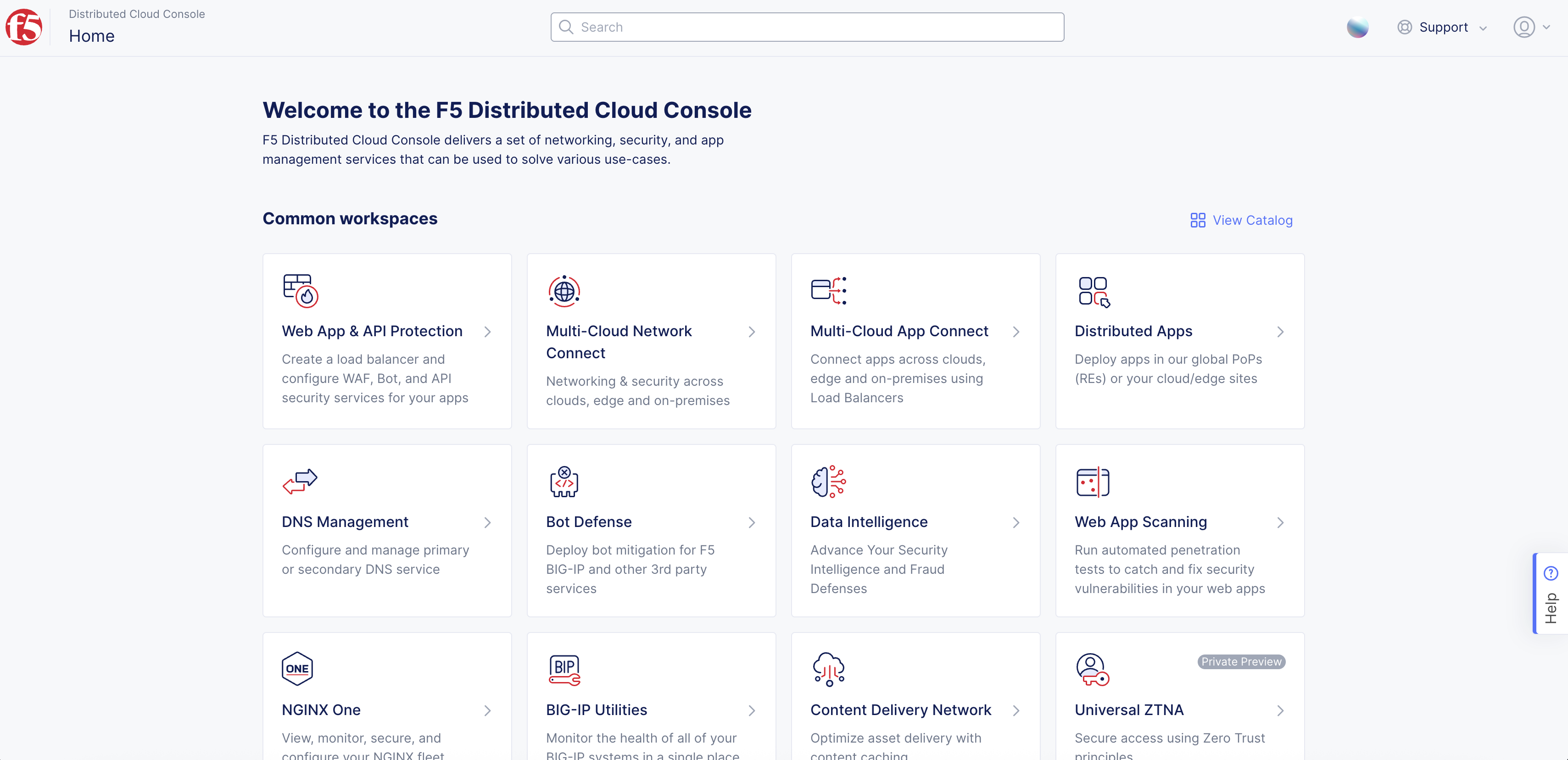
Figure: Console Homepage
-
Click
Manage>Site Management>GCP VPC Sites. -
Click
Add GCP VPC Site. -
Enter
Name, enterLabels, andDescriptionas needed.
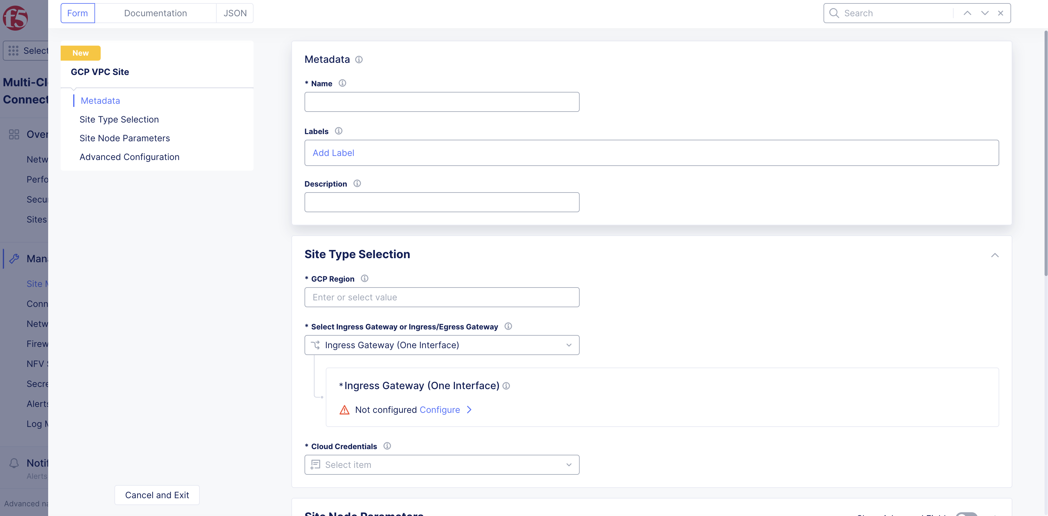
Figure: GCP Site Set Up
Step 2: Configure GCP VPC region.
From the GCP Region drop-down menu, click See Common Values to select a region.
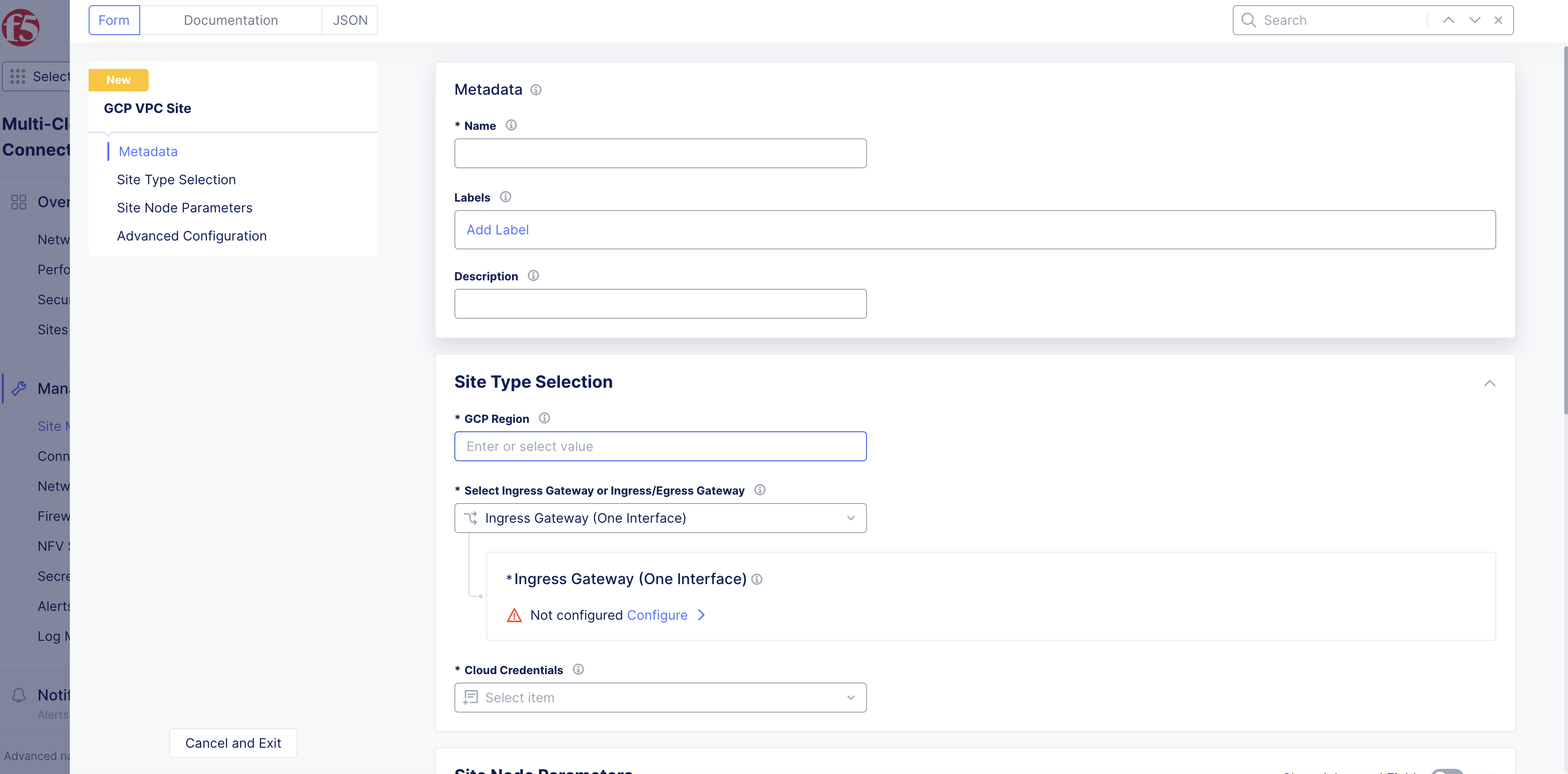
Figure: Select Region
Step 3: Configure site type settings.
-
From the
Select Ingress Gateway or Ingress/Egress Gatewaydrop-down menu, select an option:-
Ingress Gateway (One Interface) -
Ingress/Egress Gateway (Two Interface) -
App Stack Cluster (One Interface)
-
Ingress Gateway (one interface)
-
For the
Ingress Gateway (One Interface)option, clickConfigure. -
From the
GCP zone nameslist, clickSee Suggestionsto select an option that matches the configuredGCP Region. -
From the
Number of main nodesmenu, select the number of control nodes for this site.1is for a single node site and3is for a multi-node site.
Important: Either a single control node site or a multi-node site with three (3) control nodes is supported. Therefore, if you are adding more than one node, ensure that there are three (3) control nodes for your site. Use
Add Itemto add different zones.
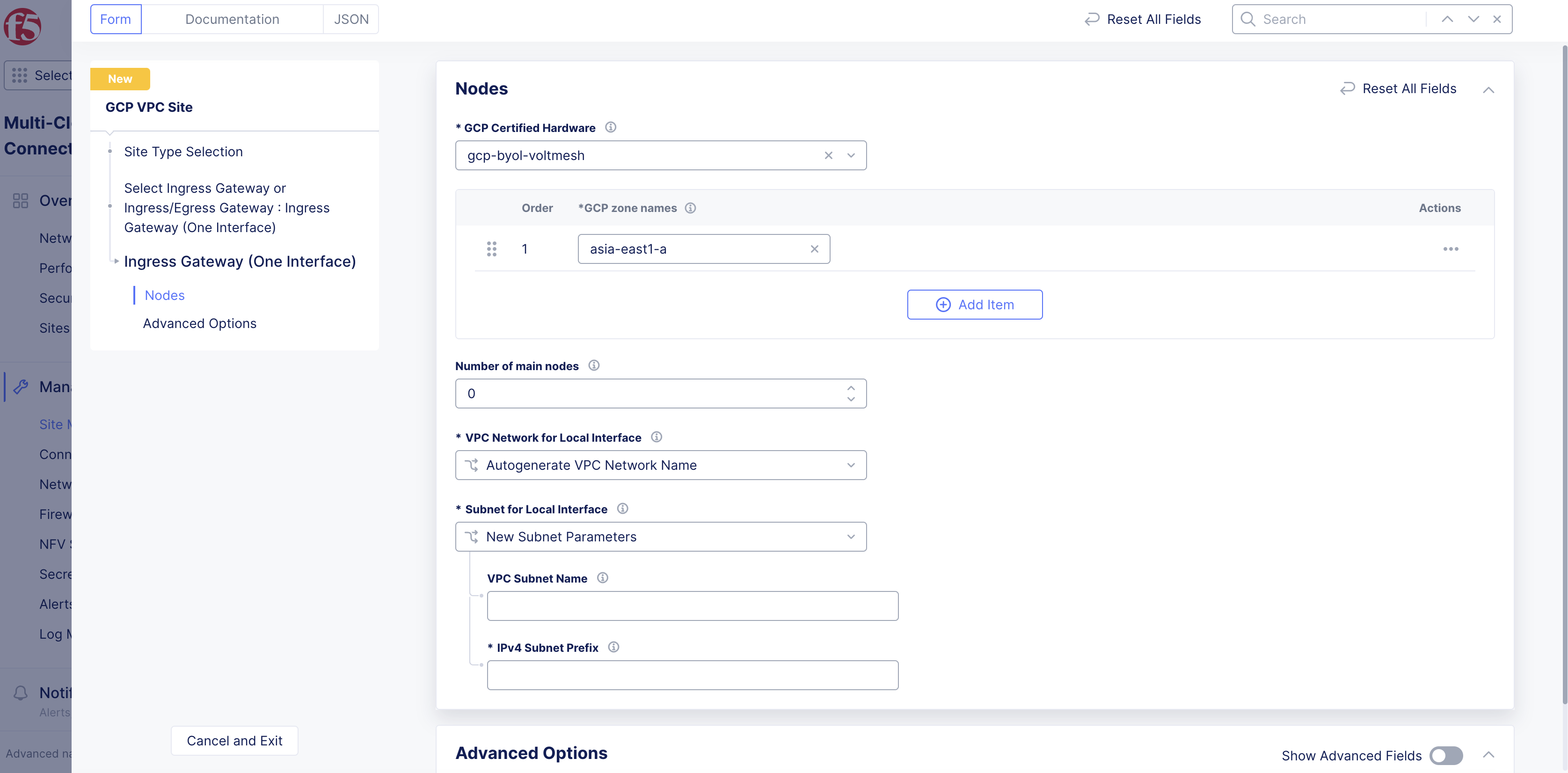
Figure: Main Nodes
-
From the
VPC Network for Local Interfacemenu, perform one of the following steps:-
Autogenerate VPC Network Name: Default option. The VPC network name is automatically generated. -
Specify VPC Network Name: Creates a network that is entered in theGCP VPC Network Namefield. -
Existing VPC Network: Specify an existing VPC network name from theGCP Regionselect previously. Enter its name in theGCP VPC Network Namefield.
-
-
From the
Subnet for Local Interfacemenu, perform one of the following:-
For the
New Subnet Parametersoption, enter a name for the subnet in theVPC Subnet Namefield and a subnet prefix in theIPv4 Subnet Prefixfield. The subnet name will be auto-generated if a name is not specified. -
For the
Existing Subnetoption, specify the existing subnet name on the existing VPC network selected above in theVPC Subnet Namefield.
-
-
In the
Advanced Optionssection, enable theShow Advanced Fieldsoption and perform the following:-
From the
Performance Modemenu, select an option: -
L7 Enhanced: This option optimizes the site for Layer 7 traffic processing. -
L3 Enhanced: This option optimizes the site for Layer 3 traffic processing. Only choose this option if the site is used for L3 connectivity and not any L7 features. Select whether to use this feature with or without jumbo frames.
-
Note: The
L3 Enhancedfeature works on CE sites with a minimum of 5 cores and a minimum of 3 GB memory. Jumbo frames (Ethernet frames with a larger payload than the Ethernet standard maximum transmission unit of 1,500 bytes) are supported forL3 Enhanced.
- Click
Applyto save the configuration.
Ingress/Egress Gateway (two interfaces)
-
For the
Ingress/Egress Gateway (Two Interface)option, clickConfigure. -
From the
GCP zone nameslist, clickSee Suggestionsto select an option that matches the configuredGCP Region. -
From the
Number of main nodesmenu, select the number of control nodes for this site.1is for a single node site and3is for a multi-node site.
Important: Either a single control node site or a multi-node site with three (3) control nodes is supported. Therefore, if you are adding more than one node, ensure that there are three (3) control nodes for your site. Use
Add Itemto add different zones.
-
From the
VPC Network for Inside Interfacemenu, perform one of the following steps:-
Autogenerate VPC Network Name: Default option. The VPC network name is automatically generated. -
Specify VPC Network Name: Creates a network that is entered in theGCP VPC Network Namefield. -
Existing VPC Network: Specify an existing VPC network name from theGCP Regionselect previously. Enter its name in theGCP VPC Network Namefield.
-
-
From the
Subnet for Inside Interfacemenu, perform one of the following steps:-
For the
New Subnet Parametersoption, enter a name in theVPC Subnet Namefield, and enter an IP address prefix in theIPv4 Subnet Prefixfield. Subnet name will be auto-generated if a name is not specified. -
For the
Existing Subnetoption, enter an existing VPC network name in theVPC Subnet Namefield for the existing VPC network selected above.
-
-
From the
VPC Network for Outside Interfacemenu, perform one of the following steps:-
Autogenerate VPC Network Name: Default option. The VPC network name is automatically generated. -
Specify VPC Network Name: Creates a VPC network name that is created in theGCP Region. Enter a name in theGCP VPC Network Namefield. -
Existing VPC Network: Specifies an existing VPC network name in theGCP Region. Enter a name in theGCP VPC Network Namefield.
-
-
From the
Subnet for Outside Interfacemenu, perform one of the following steps:-
New Subnet Parameters: enter the name in theVPC Subnet Namefield, and enter an IP address prefix in theIPv4 Subnet Prefixfield. Subnet name will be auto-generated if a name is not specified. -
Existing Subnet: Specifies an existing subnet name for the existing VPC network previously selected. Enter an existing VPC network name in theVPC Subnet Namefield.
-
-
In the
Site Network Firewallsection:- Optionally, add a firewall policy by selecting
Active Firewall PoliciesorActive Enhanced Firewall Policiesfrom theManage Firewall Policymenu. Select an existing firewall policy, or selectAdd Itemto create and apply a firewall policy orConfigurefor an enhanced version.
- Optionally, add a firewall policy by selecting
Note: See the Create Firewall Policy guide for more information.
-
From the
Manage Forward Proxymenu, select an option to use the site as a forward proxy for outgoing requests. This configuration allows you to filter Internet-bound outgoing traffic from the site:-
Disable Forward Proxyif you want clients on-site to directly connect to services on the Internet. All outbound traffic is allowed. -
Enable Forward Proxy with Allow All Policyif you want all outbound traffic to be allowed and need the CE to proxy the outbound connections and SNAT over the SLO IP. -
Enable Forward Proxy and Manage Policiesif you want the CE to proxy traffic for selected TLS domains or HTTP URLs: Select an existing forward proxy policy or selectAdd Itemto create and apply a forward proxy policy.
-
Note: See the Forward Proxy Policies guide for more information.
-
In the
Advanced Optionssection, optionally enableShow Advanced Fields. -
Select
Connect Global Networksfrom theSelect Global Networks to Connectmenu to enable site-to-site L3 connectivity, and perform the following:-
Click
Add Item. -
From the
Select Network Connection Typemenu, select an option:-
Select
Direct Site Local Inside to a Global Networkto allow subnets on the site’s VPC and subnets on other sites on the same global network to be routable to each other without NAT. -
Select
Direct Site Local Outside to a Global Networkto allow subnets on the site’s VPC to route to subnets on other sites without NAT, but disable other sites to have a route to the current site’s subnets other than the outside subnet.
-
-
From the
Global Virtual Networkmenu, select an existing global network or create a new network usingAdd Item. See the Virtual Networks guide for more information. -
Click
Apply.
-
-
From the
Select DC Cluster Groupmenu, select an option to set the site in a DC cluster group:-
Not a Member of DC Cluster Group: Default option. -
Member of DC Cluster Group via Outside Network: Select this option if other sites are reachable via SLO interface. -
Member of DC Cluster Group via Inside Network: Select this option if other sites are reachable via SLI interface.
-
Note: For more information, see the Configure DC Cluster Group guide.
-
From the
Manage Static Routes for Inside Networkmenu, selectManage Static Routes.ClickAdd Item. Perform one of the following steps:-
Select
Simple Static Routeand then enter a static route in theSimple Static Routefield. Specify the destination ina.b.c.d/mformat. The route is always added on SLI, and the ARP for the destination must resolve from the CE’s SLI. -
Select
Custom Static Routeand then clickConfigure. Perform the following steps:-
In the
Subnetssection, clickAdd Item. Select IPv4 or IPv6 option from theVersionmenu. Enter a prefix and a prefix length for the subnet. ClickApply. You can use theAdd Itemoption to set more subnets. -
In the
Nexthopsection, select a next-hop type from theTypemenu. Select IPv4 or IPv6 from theVersionmenu in theAddresssubsection. Enter an IP address. From theNetwork Interfacemenu, select an option. -
From the
Static Route Labelsfield, select supported labels usingAdd Label. You can select more than one from this list. -
From the
Attributesmenu, select supported attributes. You can select more than one from this list. -
Click
Applyto add the custom route. -
Click
Apply.
-
-
-
Select
Manage Static routesfrom theManage Static Routes for Outside Networkmenu, and clickAdd Item. Follow the same procedure as that of managing the static routes for inside network. -
From the
Site Mesh Group Connection Typemenu, select an option:-
Select
Site Mesh Group Connection via Public IPif other sites in SMG are accessible only over the Internet. -
Select
Site Mesh Group Connection via Private IPif other sites in SMG are accessible over private connectivity.
-
-
From the
Performance Modemenu, select an option:-
L7 Enhanced: This option optimizes the site for Layer 7 traffic processing. -
L3 Enhanced: This option optimizes the site for Layer 3 traffic processing. Only choose this option if the site is used for L3 connectivity and not any L7 features. Select whether to use this feature with or without jumbo frames.
-
Note: The
L3 Enhancedfeature works on CE sites with a minimum of 5 cores and a minimum of 3 GB memory. Jumbo frames (Ethernet frames with a larger payload than the Ethernet standard maximum transmission unit of 1,500 bytes) are supported forL3 Enhanced.If
L3 Enhancedis not enabled on all CE sites in a Site Mesh Group, the MTU configured on the site-to-site tunnel interfaces will not be consistent. Therefore, F5 recommends that you enable L3-focused performance mode on all sites participating in a Site Mesh Group.
- Click
Applyto save the configuration.
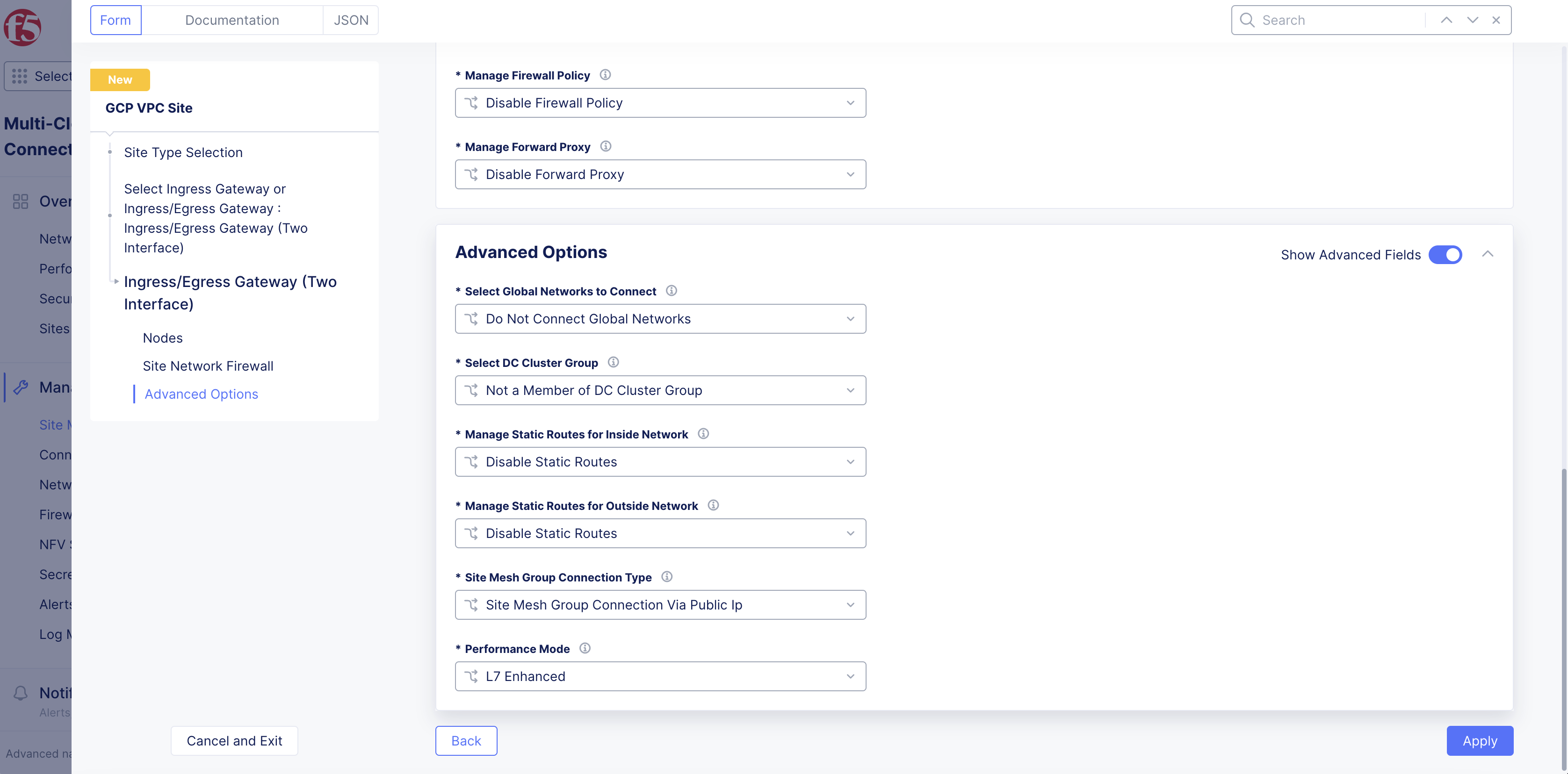
Figure: Advanced Options
App Stack Cluster (one interface)
-
For the
App Stack Cluster (One Interface)option, clickConfigure. -
From the
GCP zone nameslist, clickSee Suggestionsto select an option that matches the configuredGCP Region. -
From the
Number of main nodesmenu, select the number of control nodes for this site.1is for a single node site and3is for a multi-node site.
Important: Either a single control node site or a multi-node site with three (3) control nodes is supported. Therefore, if you are adding more than one node, ensure that there are three (3) control nodes for your site. Use
Add Itemto add different zones.
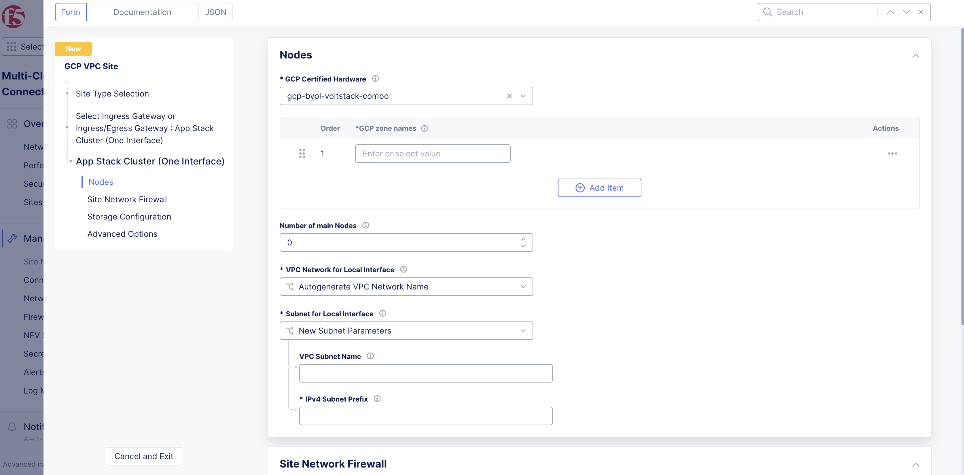
Figure: App Stack Site
-
From the
VPC Network for Local Interfacemenu, perform one of the following steps:-
Autogenerate VPC Network Name: Default option. The VPC network name is automatically generated. -
Specify VPC Network Name: Creates a network that is entered in theGCP VPC Network Namefield. -
Existing VPC Network: Specify an existing VPC network name from theGCP Regionselect previously. Enter its name in theGCP VPC Network Namefield.
-
-
From the
Subnet for Local Interfacemenu, perform one of the following:-
For the
New Subnet Parametersoption, enter a name for the subnet in theVPC Subnet Namefield and a subnet prefix in theIPv4 Subnet Prefixfield. The subnet name will be auto-generated if a name is not specified. -
For the
Existing Subnetoption, specify the existing subnet name on the existing VPC network selected above in theVPC Subnet Namefield.
-
-
In the
Site Network Firewallsection:- Optionally, add a firewall policy by selecting
Active Firewall PoliciesorActive Enhanced Firewall Policiesfrom theManage Firewall Policymenu. Select an existing firewall policy, or selectAdd Itemto create and apply a firewall policy orConfigurefor an enhanced version.
- Optionally, add a firewall policy by selecting
Note: See the Create Firewall Policy guide for more information.
-
From the
Manage Forward Proxymenu, select an option to use the site as a forward proxy for outgoing requests. This configuration allows you to filter Internet-bound outgoing traffic from the site:-
Disable Forward Proxyif you want clients on-site to directly connect to services on the Internet. All outbound traffic is allowed. -
Enable Forward Proxy with Allow All Policyif you want all outbound traffic to be allowed and need the CE to proxy the outbound connections and SNAT over the SLO IP. -
Enable Forward Proxy and Manage Policiesif you want the CE to proxy traffic for selected TLS domains or HTTP URLs: Select an existing forward proxy policy or selectAdd Itemto create and apply a forward proxy policy.
-
Note: See the Forward Proxy Policies guide for more information.
-
In the
Storage Configurationsection, enable theShow Advanced Fieldsoption. -
From the
Select Configuration for Storage Classesmenu, selectAdd Custom Storage Classif you want to use a user-created storage class for storage devices or external storage deployed outside F5 Distributed Cloud Services. -
Click
Add Item. -
In the
Storage Class Namefield, enter a name for the storage class as it will appear in Kubernetes. -
Optionally, enable the
Default Storage Classoption to make this new storage class the default class for all clusters. -
Click
Apply. -
Optionally, configure more settings in the
Advanced Optionssection by enablingShow Advanced Fields. -
Select
Connect Global Networksfrom theSelect Global Networks to Connectmenu to enable site-to-site L3 connectivity, and perform the following:-
Click
Add Item. -
From the
Select Network Connection Typemenu, select an option:-
Select
Direct Site Local Inside to a Global Networkto allow subnets on the site’s VPC and subnets on other sites on the same global network to be routable to each other without NAT. -
Select
Direct Site Local Outside to a Global Networkto allow subnets on the site’s VPC to route to subnets on other sites without NAT, but disable other sites to have a route to the current site’s subnets other than the outside subnet.
-
-
From the
Global Virtual Networkmenu, select an existing global network or create a new network usingAdd Item. See the Virtual Networks guide for more information. -
Click
Apply.
-
-
From the
Select DC Cluster Groupmenu, select an option to set the site in a DC cluster group:-
Not a Member of DC Cluster Group: Default option. -
Member of DC Cluster Group via Outside Network: Select this option if other sites are reachable via SLO interface. -
Member of DC Cluster Group via Inside Network: Select this option if other sites are reachable via SLI interface.
-
Note: For more information, see the Configure DC Cluster Group guide.
-
From the
Site Mesh Group Connection Typemenu, select an option:-
Select
Site Mesh Group Connection via Public IPif other sites in SMG are accessible only over the Internet. -
Select
Site Mesh Group Connection via Private IPif other sites in SMG are accessible over private connectivity.
-
-
From the
Manage Static Routes for Site Local Networkmenu, select an option:-
Disable Static Routes: Default option. No new static routes are created. -
Manage Static Routes: Add a new static route: ClickAdd Item. Perform one of the following steps: -
Select
Simple Static Routeand then enter a static route in theSimple Static Routefield. Specify the destination ina.b.c.d/mformat. The route is always added on SLI, and the ARP for the destination must resolve from the CE’s SLI. -
Select
Custom Static Routeand then clickConfigure. Perform the following steps:-
In the
Subnetssection, clickAdd Item. Select IPv4 or IPv6 option from theVersionmenu. Enter a prefix and a prefix length for the subnet. ClickApply. You can use theAdd Itemoption to set more subnets. -
In the
Nexthopsection, select a next-hop type from theTypemenu. Select IPv4 or IPv6 from theVersionmenu in theAddresssubsection. Enter an IP address. From theNetwork Interfacemenu, select an option. -
From the
Static Route Labelsfield, select supported labels usingAdd Label. You can select more than one from this list. -
From the
Attributesmenu, select supported attributes. You can select more than one from this list. -
Click
Applyto add the custom route. -
Click
Apply.
-
-
-
From the
Site Local K8s API accessmenu, select an option:-
Disable Site Local K8s API access: Select this option if you do not want to access the k8s API for the site directly and instead are using it as one of the sites in Virtual Kubernetes (vk8s) and want to access it via vk8s API only. -
Enable Site Local K8s API access: Select this option if you want to configure the site for managed K8s and want to access the site’s API endpoint directly. From theEnable Site Local K8s API accessmenu, select an existing managed K8s cluster name or create a new one by clicking onAdd Item.
-
Note: Distributed Cloud Services support both mutating and validating webhooks for managed K8s. Webhook support can be enabled in the K8s configuration. For more information, see the Create K8s Cluster guide.
- Click
Apply.
Step 4: Select cloud credentials.
Refer to the Cloud Credentials guide for more information. Ensure that the GCP credentials are applied with required access policies as per the Policy Requirements document.
-
From the
Cloud Credentialsmenu, select your existing GCP credentials object, or clickAdd Itemto load the credential creation wizard. -
To create new credentials, use the following guidelines:
-
Enter a name in the
Metadatasection. -
Optionally, set labels and enter a description.
-
From the
Select Cloud Credential Typemenu, selectGCP Credentials. -
Click
Configure. -
Select an option for the
Secret Info:-
If you select
Blindfold Secret, enter the secret in the field, and then clickBlindfold. -
If you select
Clear Secret, enter the secret in one of the formats displayed.
-
-
Note: The secret is your GCP service account keys in JSON format.
- Click
Apply.
Step 5: Set the site node parameters.
-
In the
Site Node Parameterssection, enable theShow Advanced Fieldsoption. -
From the
GCP Instance Type for Nodemenu, select the instance type usingSee Common Values. -
In the
Public SSH keybox, enter the public key used for SSH purposes. -
Optionally, configure the
Cloud Disk Sizeoption. The minimum disk size is 80 GB for mesh sites and 100 GB for App Stack Sites. -
Optionally, add a geographic address and enter the latitude and longitude values. The coordinates will be auto-populated based on the GCP region selected, but you have the option to override it. The coordinates allow the site to be shown in a proper location on the site map on the dashboard.
Step 6: Configure the advanced options.
-
In the
Advanced Configurationsection, enable theShow Advanced Fieldsoption. -
From the
Logs Streamingmenu, selectEnable Logs Streamingto configure the syslog server. KeepDisable Logs Streamingselected if streaming is not required. -
From the
F5XC Software Versionmenu, keep the default selection ofLatest SW Versionor selectF5XC Software Versionto specify an older version number. -
From the
Operating System Versionmenu, keep the default selection ofLatest OS Versionor selectOperating System Versionto specify an older version number. -
From the
Node by Node Upgrademenu, keep the default selection ofEnableto ensure your CE nodes are updated efficiently and in parallel with one another. Configure the corresponding options to suite your requirements. -
For
GCP Labels, useAdd Labelto link sites together using a label. A maximum of thirty (30) tags are supported per instance. -
From the
Offline Survivability Modemenu, selectEnable Offline Survivability Mode. This action will restart all pods for your site. For more information, see the Manage Site Offline Survivability guide.
Step 6.1: Optionally, configure private link.
-
From the
Private Connectivity To Sitedrop-down menu, select an option:-
Disable Private Connectivity: Default option. -
Enable Private Connectivity: Enables a private link to your cloud site. For more information, see the CloudLink guide.
-
Step 6.2: Configure blocked services from site.
-
From the
Services to be blocked on sitemenu, select the service you want to be blocked/allowed on the CE node. This configuration only blocks access to the services running on the CE nodes and not to the services to which the CE is acting as a load balancer or a default gateway. See the following options:-
Block DNS, SSH & WebUI services on Site: Default option. -
Allow access to DNS, SSH & WebUI services on Site: Select this option to allow incoming traffic to these services. -
Custom Blocked Services Configuration: Select this option and clickAdd Itemto block specific services. Select the service to block (DNS or SSH) on the SLO or SLI network from theBlocked Services Value Typemenu.
-
Step 7: Complete the site object creation.
New VPC Site
Click Add GCP VPC Site to complete creating the site. The Status field for the site object displays Validation in progress. After validation, the field displays Validation Succeeded.
Existing VPC Site
If you use an existing VPC, Console will validate whether certain existing objects are available and valid. This provides current information to help troubleshoot and fix any potential issues without having to wait until the full site deployment process completes.
After you click Save GCP VPC Site, the validation process begins and is displayed as Validation in progress.
If the site deployment validation failed, a message with Validation Failed will be displayed. Click on the tooltip to display a popup message with the error.
If the site deployment validation succeeded, a message with Validation Succeeded will be displayed.
Note: The
QUEUEDstate references a site status action that is in process. The site status will remain inQUEUEDstate until the backend service is ready to executeApply/Plan/Destroycommands. The site status (under theStatuscolumn) is updated on the Console once the execution begins. After a maximum duration of 15 minutes, the site will stay in theQUEUEDstate until the status times out, after which a new state is set asPROVISION_TIMEOUT.
Deploy Site
Creating the GCP VPC site object in Console generates the Terraform parameters.
Step 1: Deploy site.
-
Navigate to the GCP VPC site object by clicking
Manage>Site Management>GCP VPC Sites. -
Find your GCP VPC site object and click
Applyunder theStatuscolumn. TheStatuscolumn for the site object changes first toQueuedand then toApplying.
Note: Optionally, you can perform Terraform plan activity before the deployment. Find your GCP VPC site object and click
...>Plan (Optional)to generate the execution plan for Terraform.
-
Wait for the status to change to
Applied. -
To check the status for the apply action, click
...>Terraform Parametersfor site object, and select theApply Statustab.
Step 2: Confirm site deployed and online.
-
Navigate to
Multi-Cloud Network Connect>Overview>Infrastructure>Sites. -
Verify status is
Online. It takes a few minutes for the site to deploy and status to change toOnline.
Note: You cannot add worker nodes. You can use SSH to log in to your node with username
cloud-userand your private key.
Delete VPC Site
You have two options when deleting a site in Console. You delete the site entirely, with all its resources and configuration. Or you can simply delete the site, its resources, but maintain the existing configuration (so that it can be re-applied at a later time).
Note: Deleting the VPC object deletes the sites, nodes, the VPC, and other objects created in the cloud for the site. This action also removes the site object from Console and cannot be undone.
Destroying a site deployed on an existing VPC will leave the subnets used for Site Local Outside, Site Local Inside, and Workload subnets without any explicit route associations.
Delete Site Completely
-
Navigate to
Manage>Site Management>GCP VPC Sites. -
Locate the site object.
-
Select
...>Delete. -
Click
Deletein pop-up confirmation window. In case the delete operation does not remove the object and returns any error, check the error from the status, fix the error, and re-attempt the delete operation. If the problem persists, contact technical support. You can check the status using the...>Terraform Parameters>Apply statusoption.
Delete Site but Maintain Configuration
-
Navigate to
Manage>Site Management>GCP VPC Sites. -
Locate the site object.
-
Click
Destroyfor your site. Alternately, click...>Destroy. -
In the pop-up window, type
DELETE. -
Click
Destroyto confirm the action. On successful operation, the site status will showDestroyedand theApplybutton will appear on the row of your site. This can be used to create the site again at a later time, if required. The site object is no longer required and can be removed from Console by clickingDeletein theActionsmenu for the site.
Deploy Site Using Terraform
This chapter provides instructions on how to create a single-node or multi-node site on GCP with Terraform.
Perform the following procedure to deploy a site using Terraform:
Step 1: Confirm Terraform is installed.
In a terminal, enter terraform version. If you need to install, follow the instructions in the official guide.
Step 2: Create API credentials file.
Log into Console and create an API 12 certificate file and then download it. Use the instructions at Credentials for more help.
Step 3: Create a new directory on your system to place files for deployment.
Create a new directory on your system to place files for deployment.
Step 4: Create the deployment file.
-
Create a file and name it
main.tffile, and place it in the newly created directory. -
Copy and paste the following information into the file:
terraform { required_version = ">= 0.13.1" required_providers { volterra = { source = "volterraedge/volterra" } }}variable "site_name" {}variable "gcp_cred_file" {}variable "gcp_instance_type" { default = "n2-standard-8"}variable "gcp_region" { default = "us-east1"}variable "gcp_az" { default = "us-east1-b"}variable "outside_subnet_cidr_block" { default = "192.168.0.0/25"}resource "volterra_cloud_credentials" "gcp_cred" { name = format("%s-cred", var.site_name) namespace = "system" gcp_cred_file { credential_file { clear_secret_info { url = format("string:///%s", base64encode(file(var.gcp_cred_file))) } } }}resource "volterra_gcp_vpc_site" "site" { name = var.site_name namespace = "system" ssh_key = "ssh-rsa XXXX" cloud_credentials { name = volterra_cloud_credentials.gcp_cred.name namespace = "system" } gcp_region = var.gcp_region instance_type = var.gcp_instance_type ingress_gw { gcp_certified_hw = "gcp-byol-voltmesh" gcp_zone_names = [var.gcp_az] local_network { new_network { name = "outside-network" } } node_number = 1 local_subnet { new_subnet { primary_ipv4 = var.outside_subnet_cidr_block subnet_name = "outside-subnet" } } } lifecycle { ignore_changes = [labels] }}resource "volterra_tf_params_action" "apply_gcp_vpc" { site_name = volterra_gcp_vpc_site.site.name site_kind = "gcp_vpc_site" action = "apply" wait_for_action = true ignore_on_update = true}-
Open the file and configure any necessary fields. You can change the parameters for your particular setup.
-
Save the changes and then close the file.
Step 5: Create file for variables.
-
In the same directory, create another file for variables and name it
terraform.tfvars. -
Create and assign the following variables:
-
For your site name, type a name within double quotes:
site_name = "<site-name>" -
For the GCP region, type the name within double quotes:
gcp_region = "<region-name>" -
For the GCP availability zone, type the name within double quotes:
gcp_az = "<gcp-az-name>" -
For the credential file, type the name within double quotes:
gcp_cred_file = "<gcp-credential-file-location>"
-
site_name = <site-name>gcp_region = <region-name>gcp_az = <gcp-az-name>gcp_cred_file = <gcp-credential-file-location>Step 6: Create and export variables for credentials and secret keys.
-
In the terminal, create and export the following variables:
-
Create this variable and assign it your API credentials password:
export VES_P12_PASSWORD=<credential-password> -
Create this variable and assign it the path to the API credential file previously created and downloaded from Console:
export VOLT_API_P12_FILE=<path-to-local-p12-file> -
Create this variable and assign it the URL for your tenant. For example:
export VOLT_API_URL=https://example.console.ves.volterra.io/api
-
Note: You can also create and save these variables in the
terraform.tfvarsfile. However, this may pose a security risk. Use caution when working with your credentials and secret keys.
export VES_P12_PASSWORD=<credential-password>export VOLT_API_P12_FILE=<path-to-local-p12-file>export VOLT_API_URL=https://example.console.ves.volterra.io/apiStep 7: Initiate Terraform process.
Enter terraform init.
Step 8: Apply Terraform process.
-
Enter
terraform apply. -
If prompted for the access key and secret key encoded in Base64, enter both.
-
Enter
yesto confirm. This may take a few minutes to complete. After the process is complete, the output will stateApply complete!. -
In Console, navigate to the list of sites and confirm the site was applied.
Destroy Site
Perform the following procedure to destroy the site using Terraform:
-
Enter
terraform destroy. -
If prompted for the access key and secret key encoded in Base64, enter both.
-
Enter
yesto confirm. This may take a few minutes to complete. After the process is complete, the output will stateDestroy complete!. -
In Console, navigate to the list of sites and confirm the site was destroyed.
Next Steps
After you have successfully deployed your site, you can choose to upgrade it or create a site mesh group (SMG).
- To update your site to the latest OS version, click
Upgradeunder theSoftware Versiontile on the dashboard.
Note: Site upgrades may take up to 10 minutes per site node. Once site upgrade has completed, you must apply the Terraform parameters to site via
Actionmenu on cloud site management page.
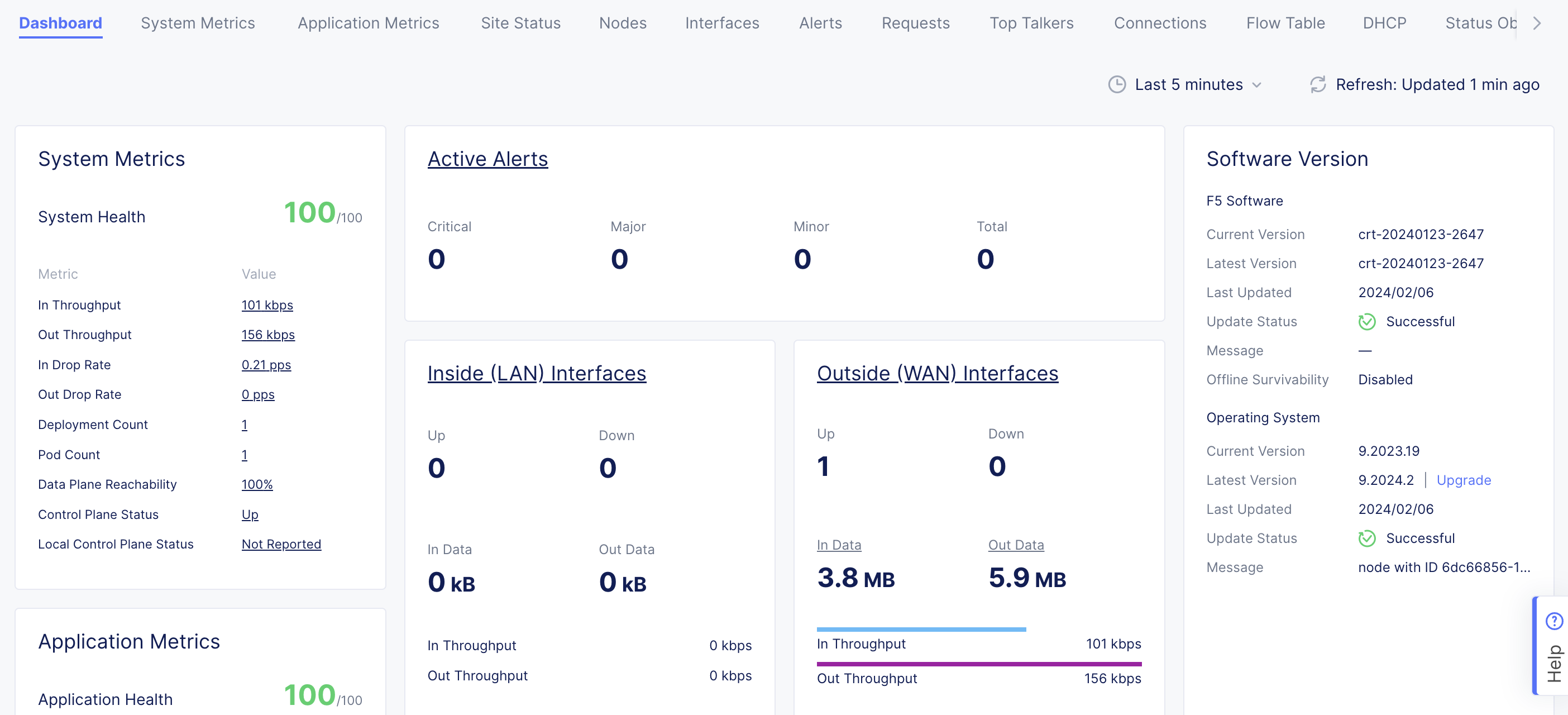
Figure: Site OS Upgrade
- To create an SMG, see the Site Mesh Group guide for more information.