Create and Advertise Virtual Host
Objective
This guide provides instructions on how to create and advertise a Virtual Host. A F5® Distributed Cloud Services virtual host is a reverse proxy that provides reachability to destinations that are in the inside network and clients that are in the outside network.
Important: It is recommended that you use virtual hosts only for advanced configuration.
Using the instructions provided in this guide, you can create a virtual host that advertises a service deployed on a site and provides reachability to the endpoint where the service is available.
Prerequisites
The following prerequisites apply:
-
A valid Account is required. If you do not have an account, see Create an Account.
-
Node or cluster image for creating a virtual host to deploy load balancing and other networking and security services within your cloud or edge location.
Configuration
The following image shows the virtual host creation workflow:
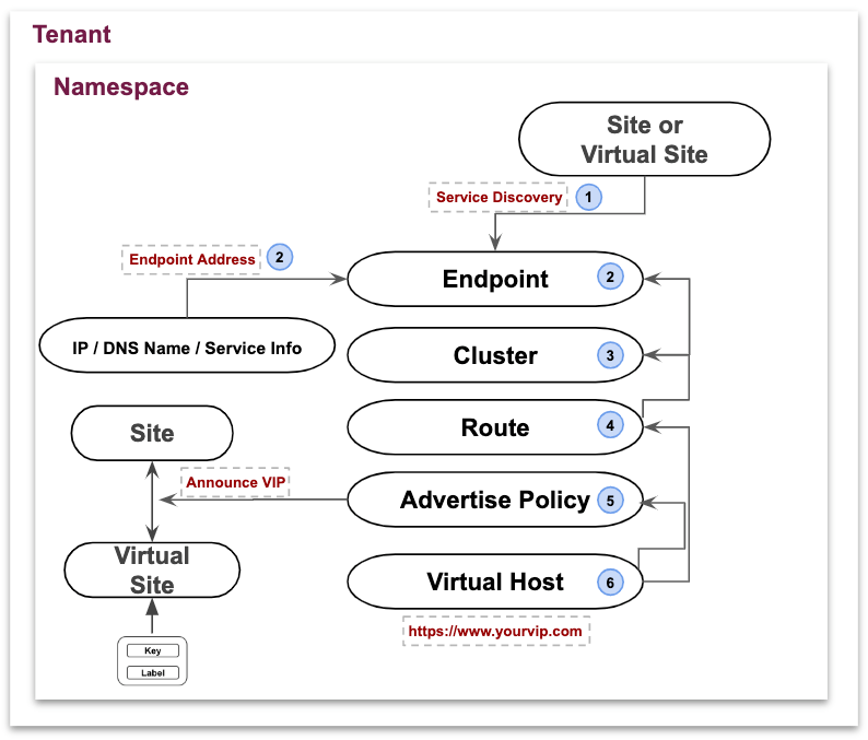
Figure: Setting Up Virtual Host
Configuration Sequence
Creating and advertising a virtual host requires performing the following sequence of actions:
| Phase | Description |
|---|---|
| Discover Service | Discover a service from a site or a virtual site. Sites are in the system namespace. Virtual sites can be created in a namespace. |
| Create Endpoint | Create an endpoint object which requires an endpoint address type. Endpoint address can be of type IP or DNS Name or Service Info. |
| Create Cluster | Create a cluster object which points to one or more endpoints in that namespace. |
| Create Route | Create a route object which maps to one or more clusters in that namespace. |
| Create Advertise Policy | Create an advertise policy object where the service can be advertised on a site or virtual site or virtual network (including the public Internet). |
| Create Virtual Host | Creates a virtual host object in a namespace where advertise policy and route are associated. |
Create Endpoint
This section provides an example for Virtual Host configuration in the Multi-Cloud App Connect service.
Note: It is recommended that you use virtual hosts only for advanced configuration and most of the virtual host functionality is now available through the HTTP Load Balancer or TCP Load Balancer.
Step 1: Navigate to endpoint creation form.
See Endpoint guide for more information.
- In Console, select the
Multi-Cloud App Connectservice.
Figure: Homepage
-
Select
Namespaceor create a namespace where an endpoint needs to be created. -
Select
Manage>Virtual Host>Endpoints. -
Select
Add Endpoint.
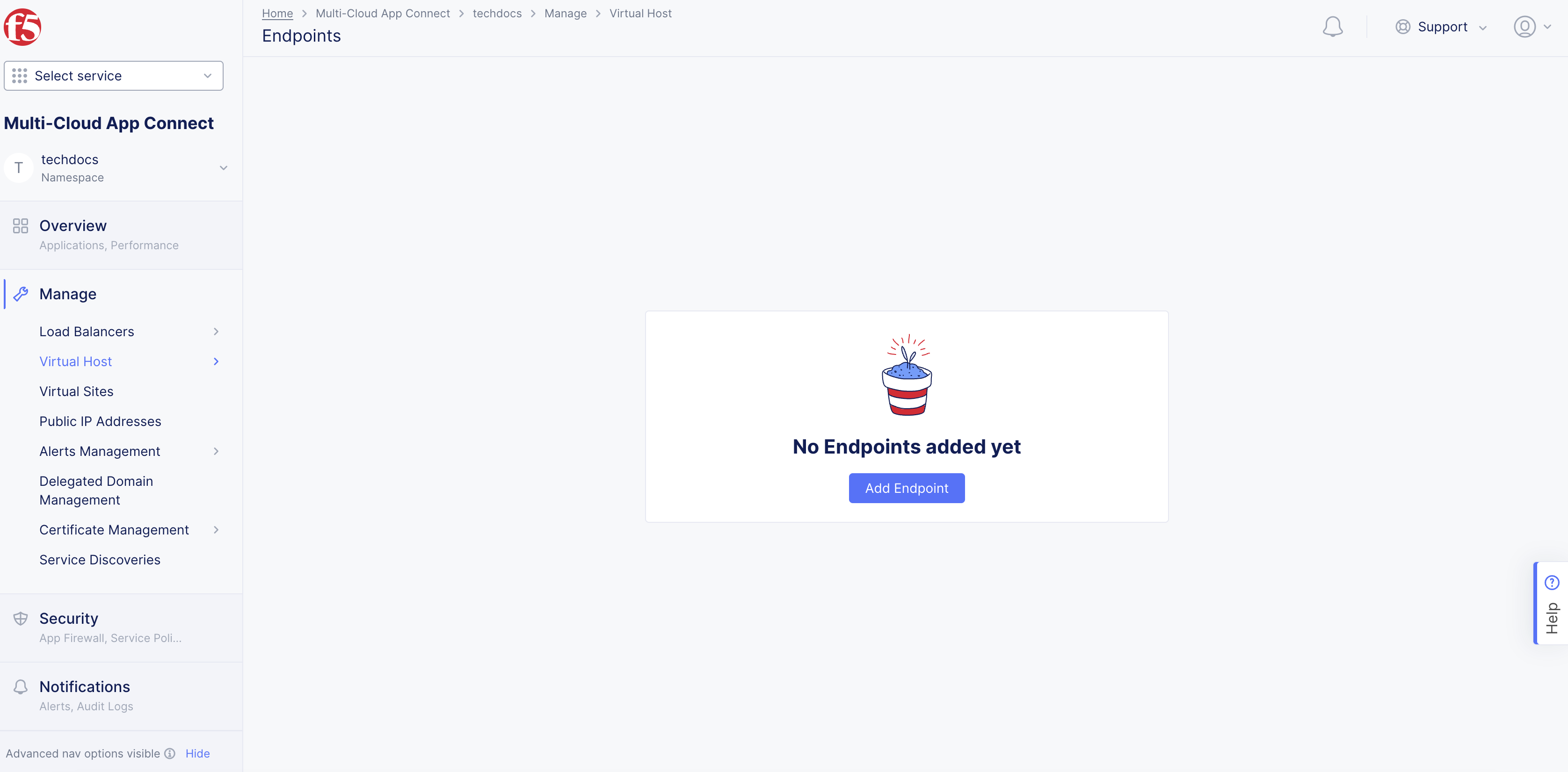
Figure: Endpoints
Step 2: Configure endpoint.
-
Enter the values per the following guidelines:
-
Name: Provide a name for identifying the endpoint object. -
Labels: Associate multiple labels from known keys/known labels or custom keys/labels. -
Description: Provide a description for the endpoint object.
-
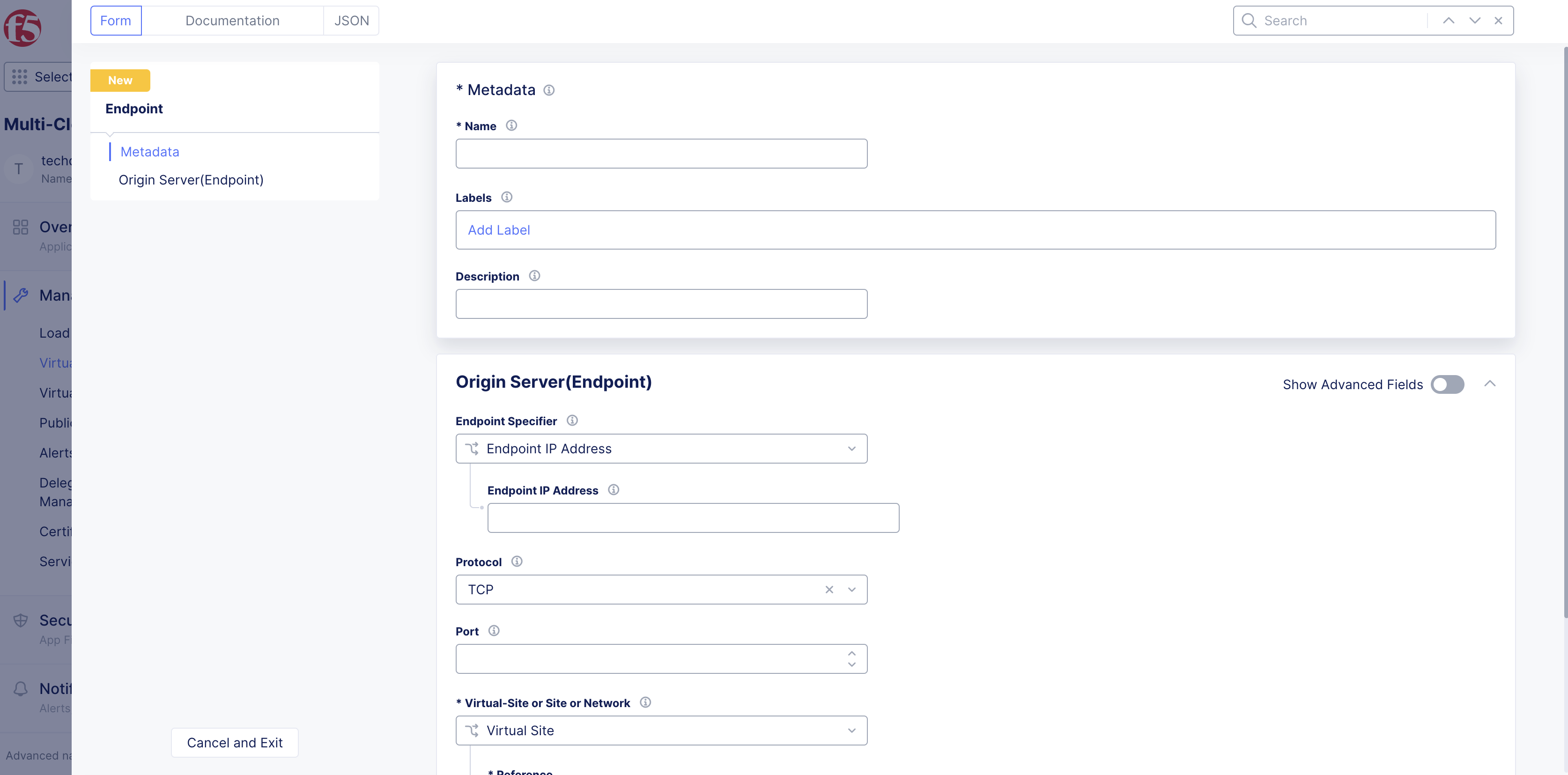
Figure: Configure Endpoint Metadata
Step 3: Configure endpoint origin server.
-
Enable the
Show Advanced Fieldsoption in theOrigin Server(Endpoint)section. -
From the
Endpoint Specifiermenu, select an option from the following:-
Endpoint IP Address: This is the IP address of the origin server. For example, if a server/service is running in a public cloud platform, like AWS, this provides the publicly reachable IP address. Enter the IP address in theEndpoint IP Addressfield. -
Endpoint Name: The endpoint's IP address is discovered using DNS name resolution. Enter the fully qualified domain name (FQDN) in theEndpoint Namefield. -
Service Selector Info: Select this option to directly discover a service running on F5 Kubernetes service or any other public cloud Kubernetes services, such as EKS, AKS, or GCP. An explicit Service Discovery object has to be created if the selected service is running on public cloud Kubernetes services. There is no need to create a Service Discovery object if the service is deployed using F5® Distributed Cloud App Stack Site (vK8s). From theDiscoverymenu, select whether a service is discovered from a K8s cluster or HashiCorp Consul service. For Kubernetes, use this when you deploy the service on F5 Kubernetes Service or any public cloud platform (EKS/AKS/GCP). Configure an extra object in case a public cloud platform is involved. If the service is hosted on F5 Kubernetes Service, then F5 seamlessly enables service discovery. For HashiCorp Consul, use this option when you have an existing Consul cluster, or create a Consul cluster for service discovery where F5 reads discovery information directly from Consul. This requires you to create a discovery object with Consul connection information.
-
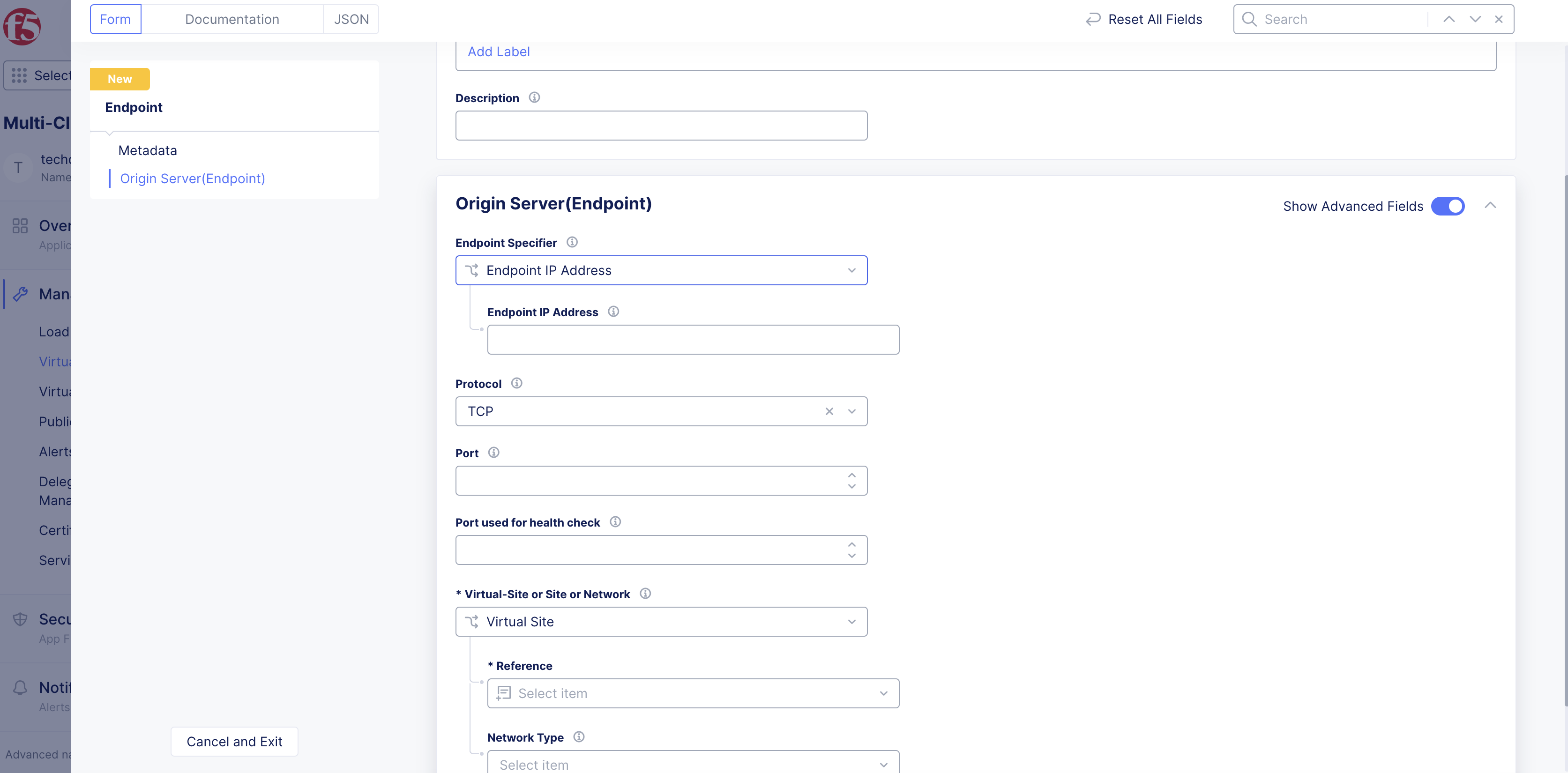
Figure: Endpoint Specifier Options
Step 4: Configure protocol and port.
Port refers to the port on which the service is serving and protocol refers to the protocol that the application uses.
-
Protocol: Default value isTCP. Both TCP and UDP protocols are supported. -
Port: Port on which the application is serving. For example, a web service application serving on port 8080.
Step 5: Configure virtual site, site, or network.
A selector can be a site, virtual site, virtual network, or known network. This defines the location from which the origin service is discovered.
-
From the
Virtual-Site or Site or Networkdrop-down menu, select an option. -
From the
ReferenceandNetwork Typedrop-down menus, select an option.
Step 6: Create endpoint.
Select Save and Exit to create the endpoint.
Create Cluster
See the Cluster guide for more information.
Step 1: Add cluster.
-
In the
Multi-Cloud App Connectservice, select the namespace in which the associated endpoint is located. -
Select
Manage>Virtual Host>Clusters. -
Select
Add Cluster.
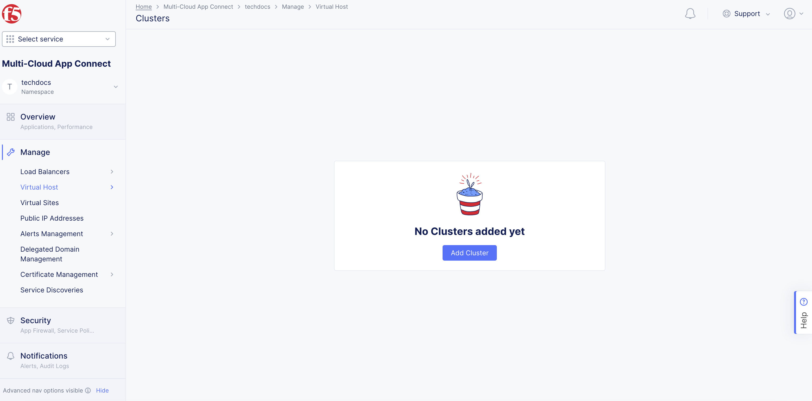
Figure: Add Cluster
Step 2: Configure cluster metadata.
-
Enter the values per the following guidelines:
-
Name: Provide a name for identifying the cluster object. -
Labels: Associate multiple labels from known keys/known labels or custom keys/labels. -
Description: Provide a description for the cluster object.
-
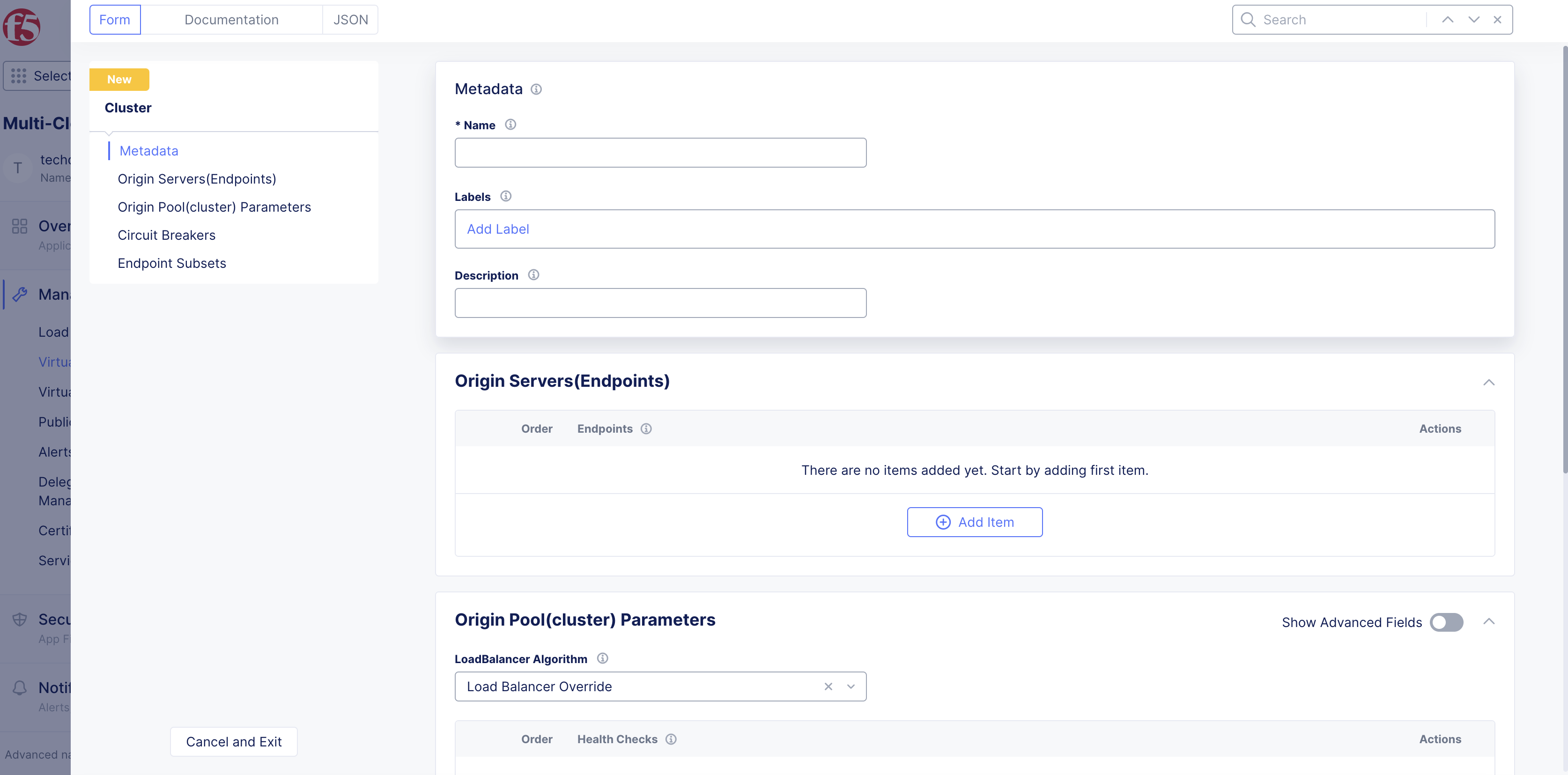
Figure: Add Cluster Metadata
Step 3: Configure endpoints associated with the cluster.
Endpoints refer to a list of endpoints that are mapped to a specific cluster. A cluster can point to one or more endpoints.
-
In the
Origin Servers(Endpoints)section, clickAdd Item. -
From the
Endpointsdrop-down menu, select an endpoint. UseAdd Itemto add new endpoints.
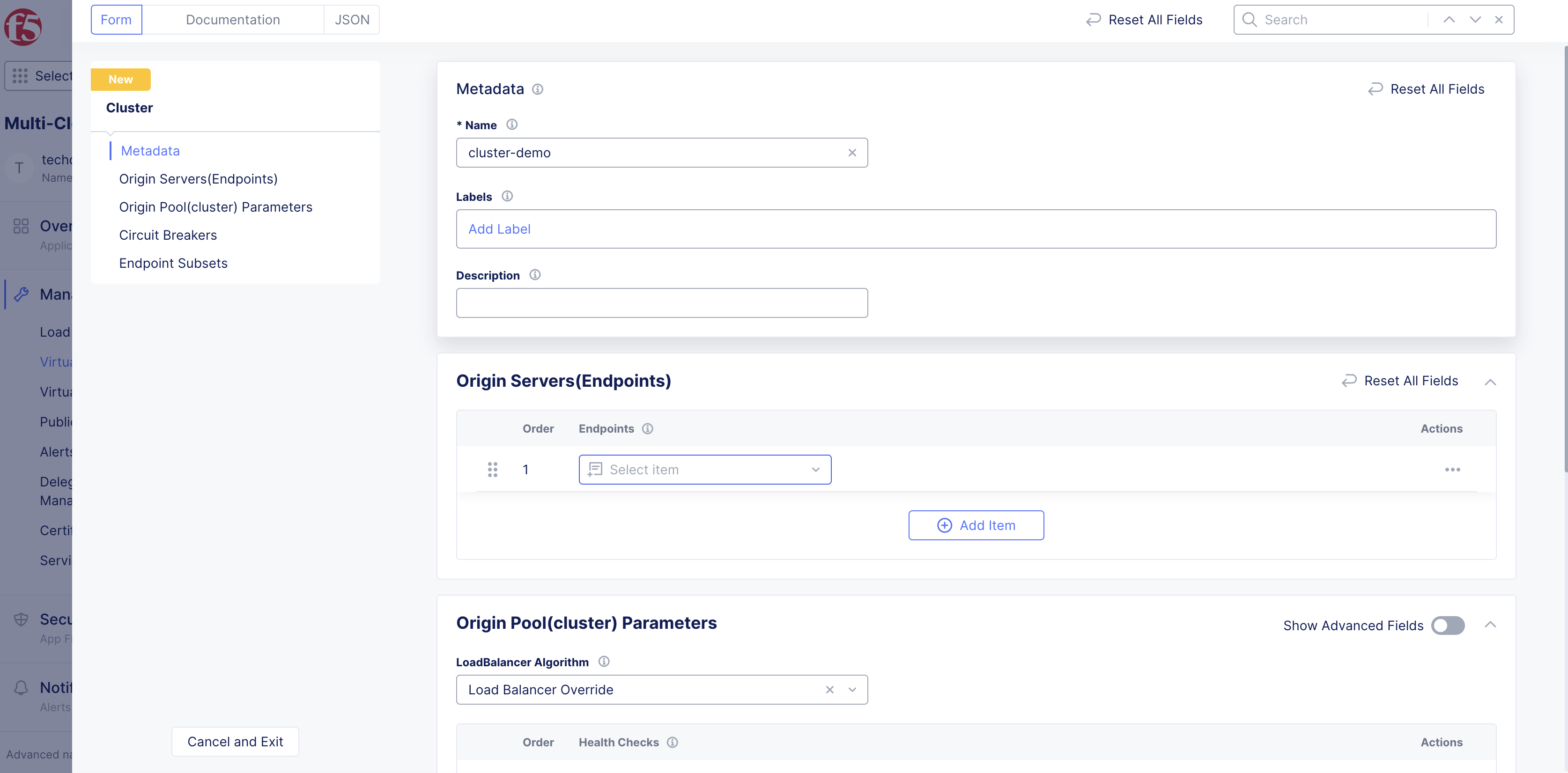
Figure: Select Cluster Endpoint
Step 4: Optionally, configure load balancer algorithm for host requests.
The load balancer algorithm refers to a specific method of load-balancing applied on the cluster object.
-
Enable the
Show Advanced Fieldsoption. -
From the
LoadBalancer Algorithmmenu, choose from the supported algorithms. If no value is configured, the default valueLoad Balancer Overrideis applied.
Step 5: Optionally, configure cluster health check.
-
Under
Health Checks, clickAdd Item. -
From the drop-down menu that appears, click
Add Item. Or select an existing object.
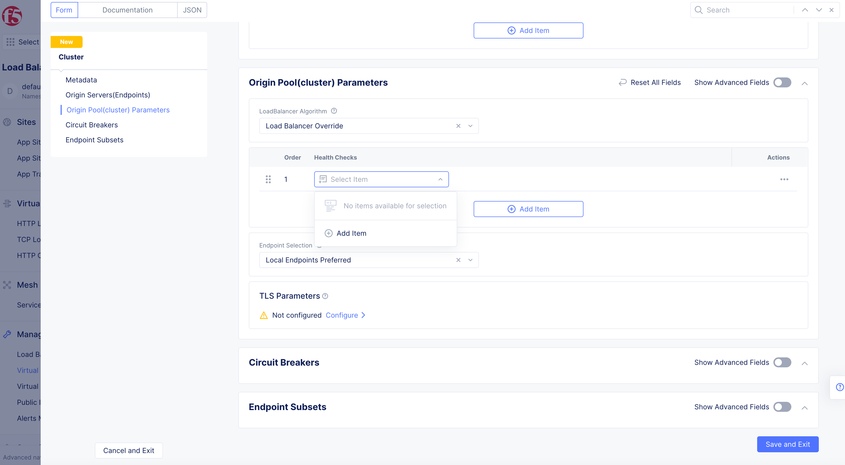
Figure: Cluster Health Check Selection
-
Enter
Name, enterLabels, andDescriptionas needed. -
Configure all other options as needed.
-
Click
Continue.
Step 6: Configure endpoint selection policy.
-
From the
Endpoint Selectiondrop-down menu, select an option:-
All Endpoints: Consider both remote and local endpoints for load balancing. -
Local Endpoints Only: Consider only local endpoints for load balancing. Enable this policy to load balance only among locally-discovered endpoints. -
Local Endpoints Preferred: Prefer the local endpoints for load balancing. If local endpoints are not present, remote endpoints will be considered.
-
Step 7: Configure TLS parameters for cluster object.
You can set TLS version and configure TLS certificates for the cluster object using TLS Parameters.
-
Select
Configurelink inTLS Parametersbox. -
From the
SNI Selectiondrop-down menu, select an option. Enter the corresponding if you selectedSNI Value. -
From the
TLS Parametersmenu,Inline TLS Parameters. -
Click
Configure. See Blindfold your TLS Certificates guide for more information. -
Select
Apply. -
Select
Apply. -
Optionally, enable the
Show Advanced Fieldsoption in theOrigin Pool(cluster) Parameterssection to configureConnection Timeout,HTTP Idle Timeout,HTTP Protocol Configuration, andPanic Threshold.
Step 8: Optionally, configure circuit breakers.
-
Enable the
Show Advanced Fieldsoption to open theCircuit Breakerssection. -
Enter values for
Priority,Connection limit,Pending Requests,Retry Count, andMaximum Request Countas needed. -
Configure
Outlier Detectioninformation as needed.
Step 9: Optionally, configure endpoint subsets for fallback policy.
An endpoint subset is a subset of endpoints grouped together using a key/value pair. Provide multiple keys and associate a label to group available endpoints. These are used in setting fallback policies.
Step 9.1: Add endpoint subsets.
-
Enable the
Show Advanced Fieldsoption to open theEndpoint Subsetssection. -
Select
Configurelink inEndpoint Subsets. -
Click
Add Item. -
Enter a key string value. You can add more than one using
Add Item. -
Click
Apply.
Step 9.2: Add fallback policy.
-
Select
Configurelink inFallback Policy. -
From the
Fallback Policymenu, select an option. -
Click
Apply.
Step 10: Save cluster object.
Select Save and Exit after all the parameters are entered in the respective fields.
Create Route
See the Route guide for more information.
Step 1: Add route.
-
In
Multi-Cloud App Connectservice, selectManage>Virtual Host. -
Select
Routes. -
Select the namespace in which the associated cluster object is located.
-
Select
Add Route.
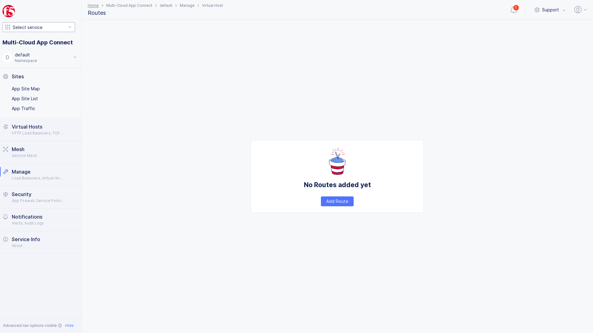
Figure: Add Route
Step 2: Configure route metadata.
-
Enter
Name,Labels, andDescriptionas needed. Enter the values per the following guidelines:-
Name: Provide a name for identifying the route object. -
Labels: Associate multiple labels from known keys/known labels or custom keys/labels. -
Description: Provide a description to the route object.
-
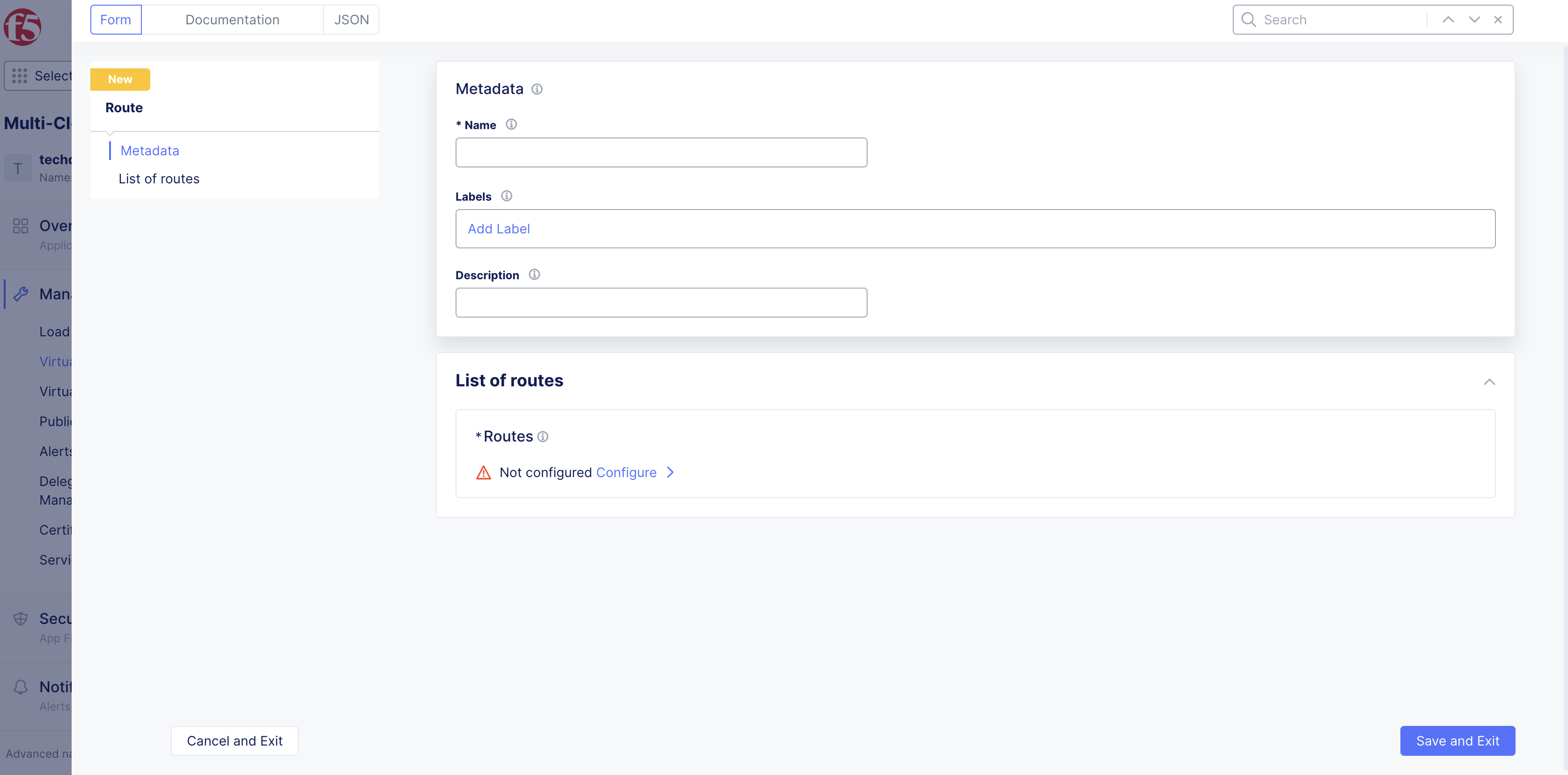
Figure: Route Metadata Configuration
Step 3: Configure routes associated with the route object.
-
Select
Configurelink inList of Routessection. -
Select
Add Item.
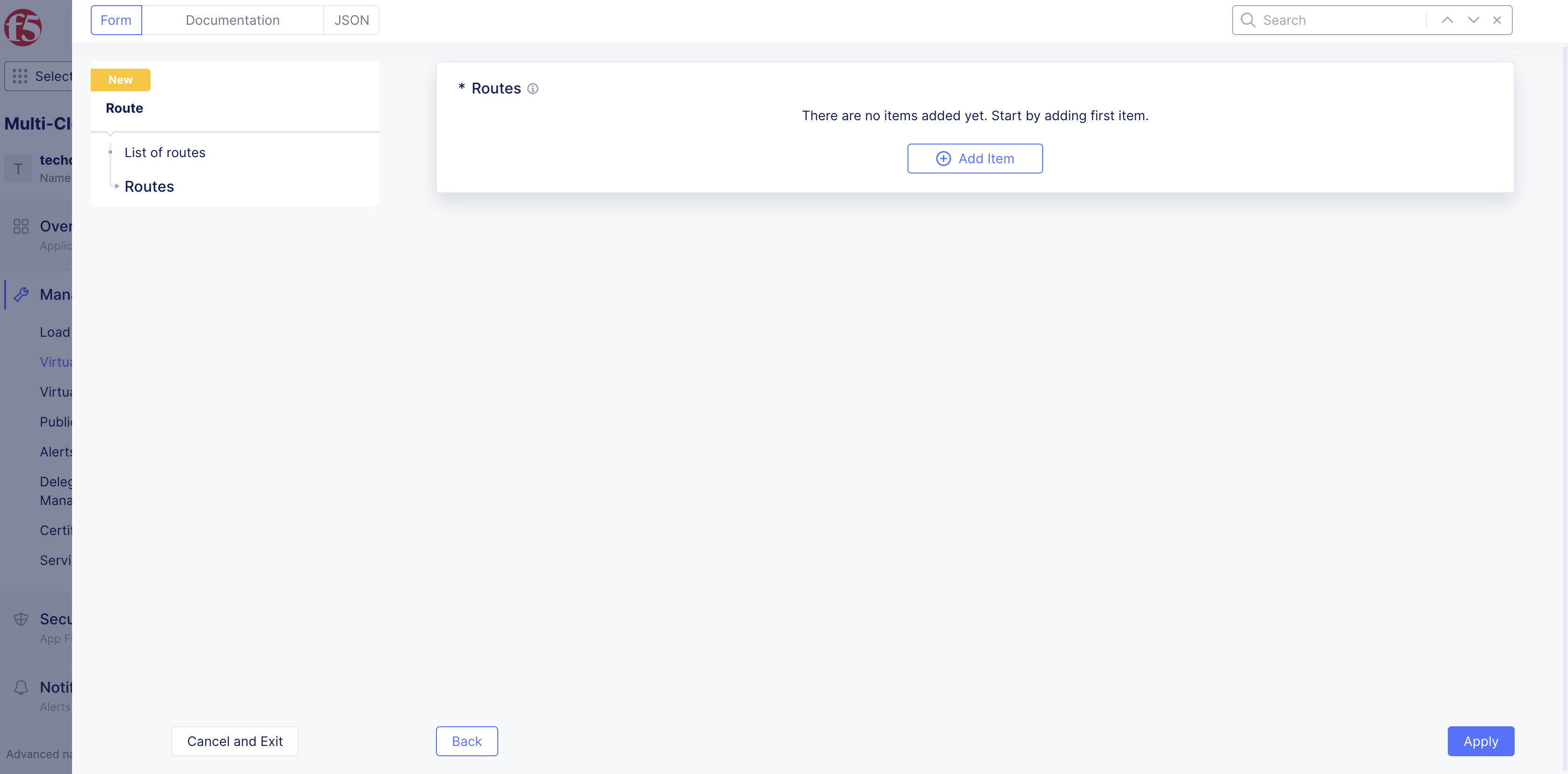
Figure: Add Route
Step 4: Implement traffic match patterns and rules based on different HTTP methods.
-
Select
Configurelink inRequest Matchsection to implement traffic match patterns and rules based on different HTTP methods. -
Select
Add Item. -
From the
HTTP Methoddrop-down menu, select an HTTP method option. -
From the
Path Matchdrop-down menu, select an option to match the HTTP method previously selected. Choose one of the three available match patterns:-
Prefix: enterPrefixvalue in box. -
Path: enterPathvalue in box. -
Regex: enterRegexvalue in box.
-
-
Optionally, specify key-value pairs using
Add ItemforQuery ParametersandHeadersoptions. -
From the
Port Matchmenu, select an option to match using ports. -
Click
Applyto save route match conditions. -
Click
Applyto add match conditions.
Step 5: Configure action for match rules.
After you configure the match criteria in the previous step, you must configure what to do (action) after a match is made.
-
Enable the
Show Advanced Fieldsoption in theActionssection. -
From the
Actionmenu, select an option from the following:-
Destination List: Route destination enables you to map one or more cluster objects to this specific route. ClickConfigureto set up a destination to send the request to. -
RedirectRedirect enables you to redirect requests received by this route. Configure the options for the redirect response. -
Direct Response: Direct response enables you to provide a response code. ClickConfigureto set up a response code and response body.
-
Step 6: Configure additional options.
-
Enable the
Show Advanced Fieldsoption in theAdvanced Actionssection. -
From the
WAF Configdrop-down menu, enable a web application firewall (WAF). -
From the
Service Policy Configurationfield, check the box to disable a service policy at the route level but not virtual host level. -
After you finish, click
Apply. -
Click
Apply.
Step 7: Save route object.
Select Save and Exit.
Create Advertise Policy
See the Advertise Policies guide for more information.
Step 1: Select the namespace.
Select the namespace in which the advertise policy needs to be created.
Step 2: Add advertise policy.
-
In
Multi-Cloud App Connect> selectManage>Virtual Host. -
Select
Advertise Policies. -
Select
Add Advertise Policy.
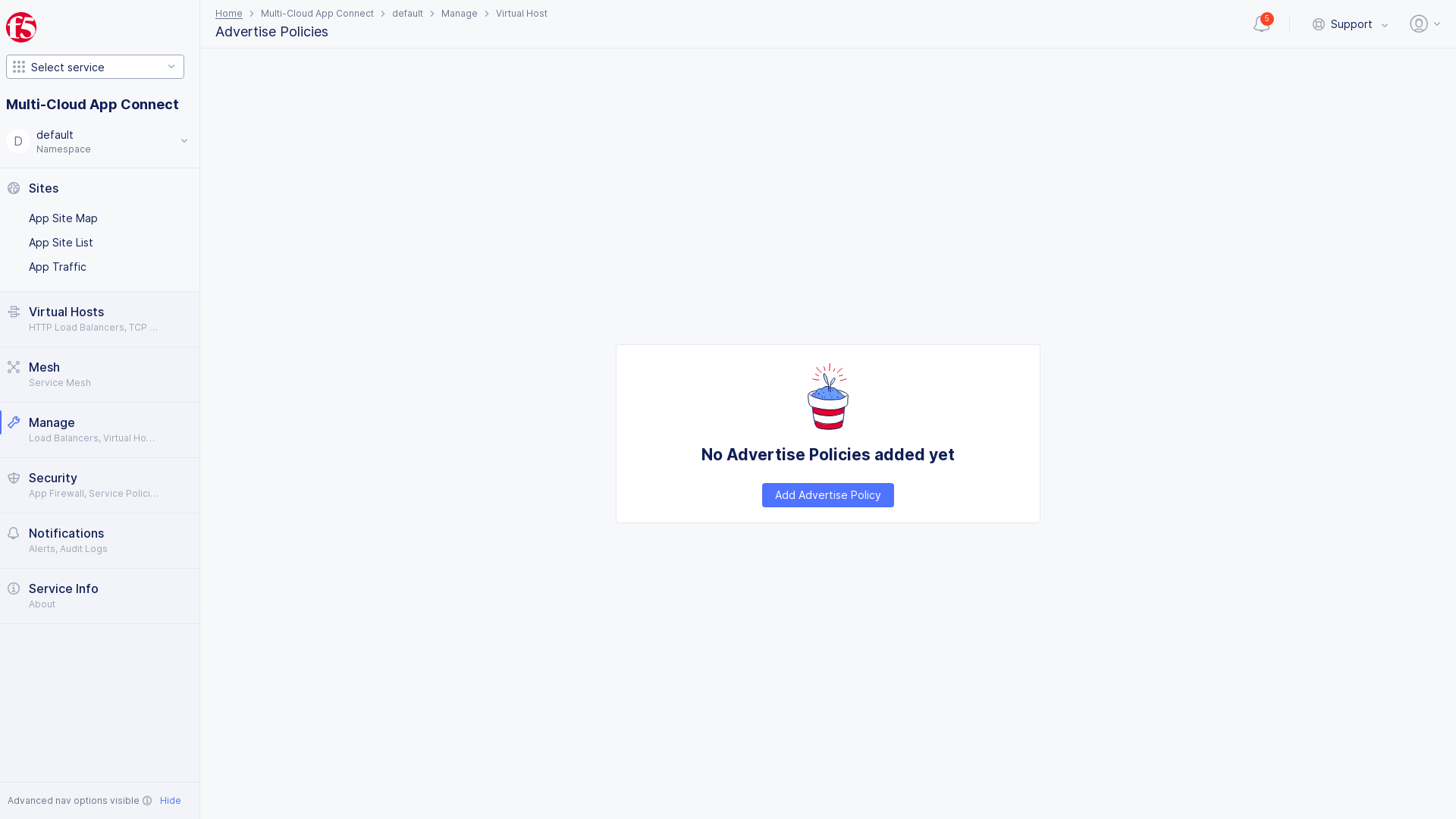
Figure: Add Advertise Policy
Step 3: Add metadata.
-
Enter a name, labels, and description in the form:
-
Name: Provides a name for identifying the advertise policy. -
Labels: Associates multiple labels from known keys/know labels or custom keys/labels. -
Description: Provides a description for the advertise policy object.
-
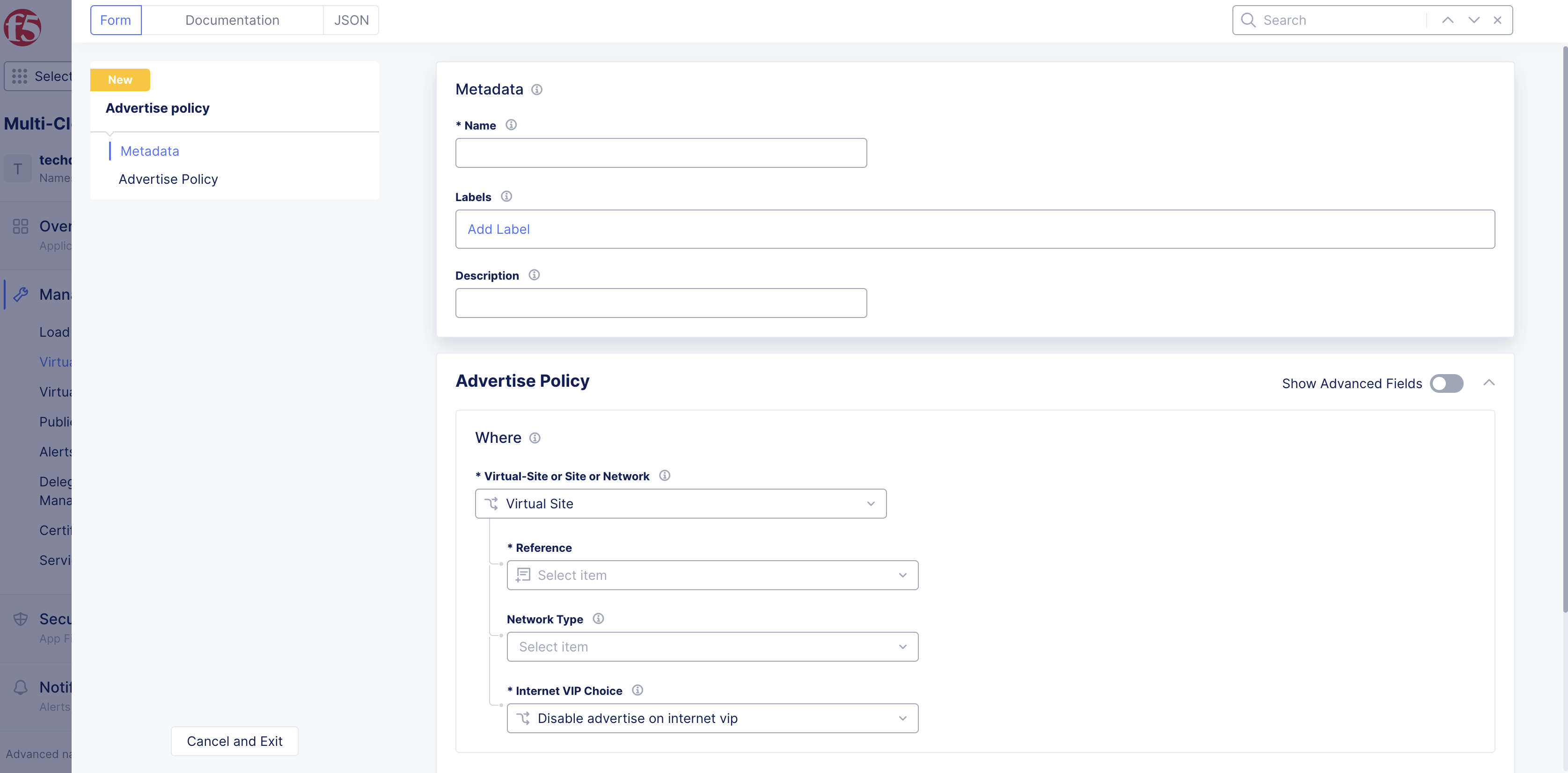
Figure: Advertise Policy Metadata
Step 4: Enter where to advertise the service.
The Where section enables you to advertise a service on a site, virtual site, and virtual network. For example, if multiple sites are spatially distributed across regions (cloud and physical), you can discover a service from one site and advertise the same on one or more sites.
-
Enable the
Show Advanced Fieldsoption in theAdvertise Policysection. -
From the
Virtual-Site or Site or Networkdrop-down menu, select an option from the following:-
Virtual Site: One or more sites grouped into a virtual site using key/label. If a virtual site has more than one site, the advertise policy will announce the services on all the sites. -
Site: A site registered and listed in theSite Listin thesystemnamespace. -
Virtual Network: A virtual network created by a user. The advertise policy advertises the service on all devices which make up the chosen virtual network.
-
-
From the
Referencedrop-down menu, select an option. -
From the
Network Typedrop-down menu, select an option. -
If you selected
Virtual SiteorSite, select theEnable advertise on internet vipoption from theInternet VIP Choicedrop-down menu.
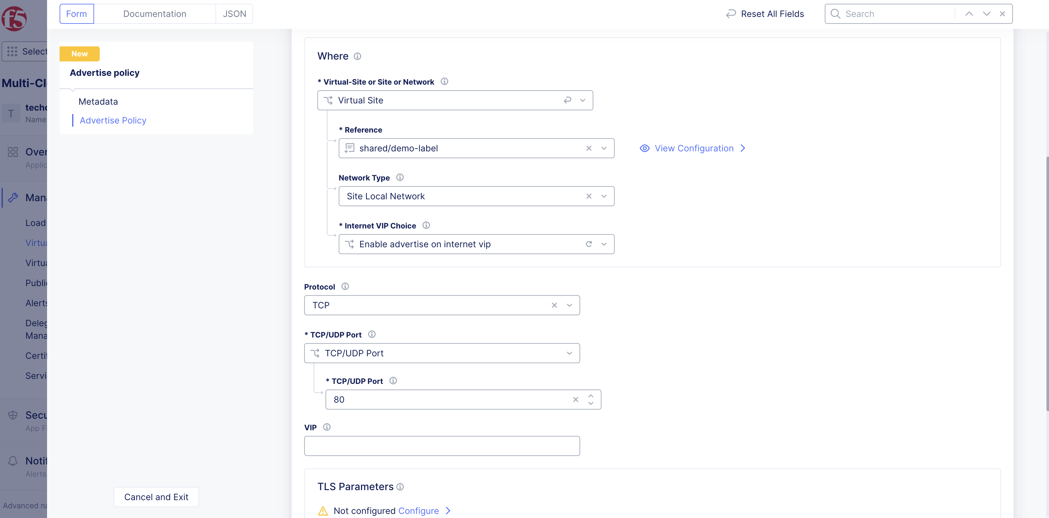
Figure: Advertise Policy Where Options
Step 5: Configure port and protocol.
-
Enable
Show Advanced Fieldsto show more options. -
From the
Protocoldrop-down menu, selectTCPorUDP. -
From the
TCP/UDP Portmenu, choose to configure a single port or port ranges.
Note:
TCP/UDP PortRefers to port on which the discovered service is advertised. This can be a different port than the originally discovered port from theEndpointobject. Advertising on public networks is supported only for ports 80 and 443.
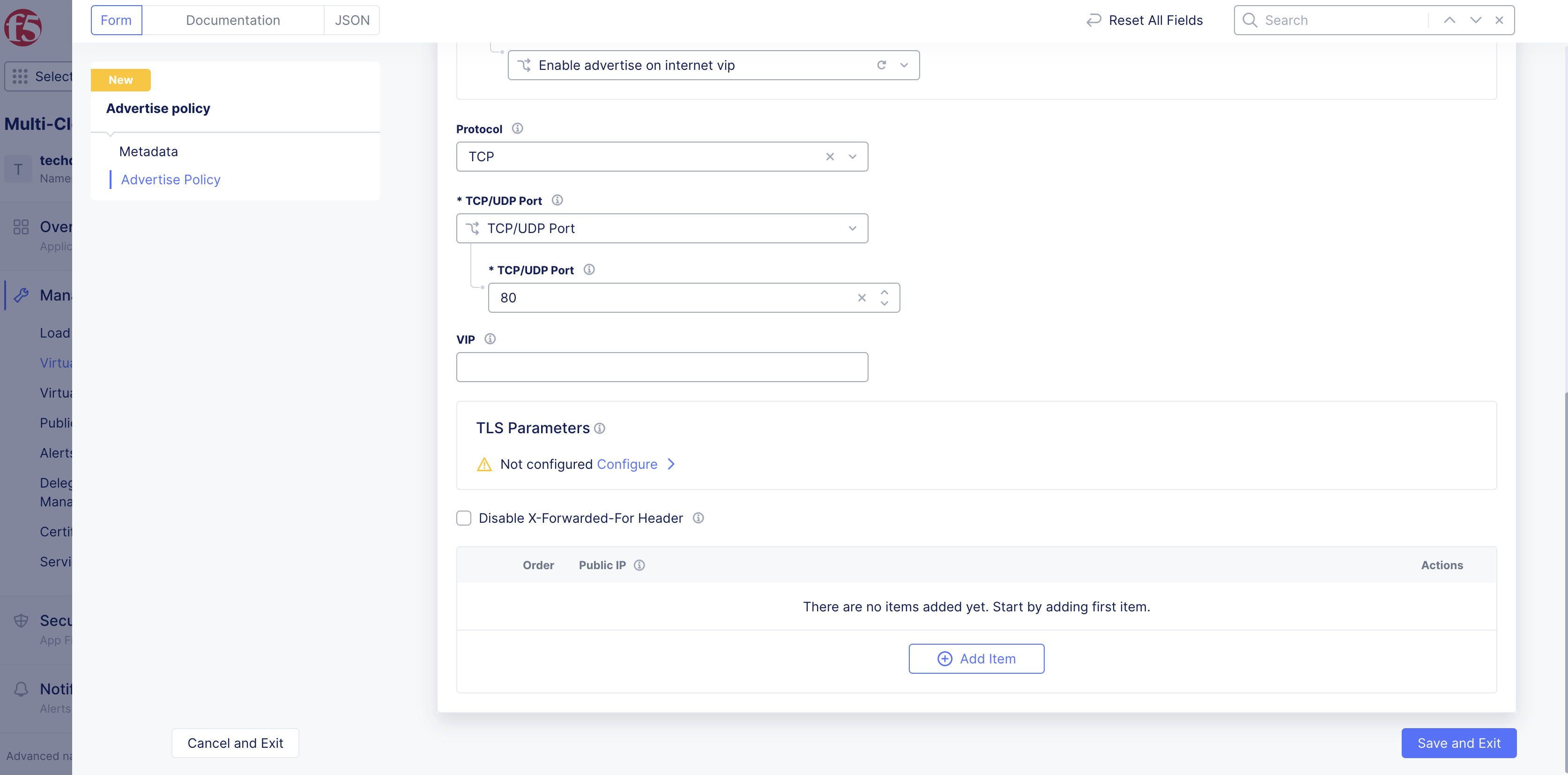
Figure: Advertise Policy Protocol and Port
Step 6: Add extra configurations as needed.
-
Optionally, enter IP address for
VIP. Must be an IPv4 or IPv6 address. -
Under
TLS Parameters, selectConfigurelink to apply custom TLS parameters for the advertise policy. -
Optionally, choose to disable the
X-Forwarded-Forheader. -
After entering all required parameters, click
Save and Exitto add the advertise policy object.
Create Virtual Host
See the Virtual Host guide for more information.
Step 1: Select the namespace.
In the Multi-Cloud App Connect service, select the namespace to create the virtual host in.
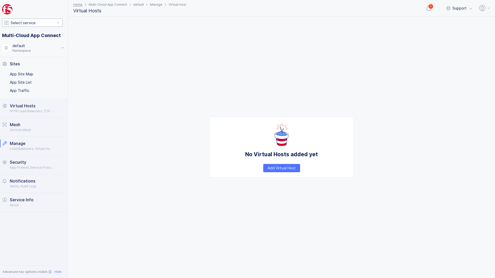
Figure: Select Namespace
Step 2: Add virtual host.
-
Select
Manage>Virtual Host>Virtual Hosts. -
Select
Add Virtual Host.
Figure: Add Virtual Host
Step 3: Enter new virtual host object information.
-
Enter name, labels, and description as needed:
-
Name: Provide a name for identifying the virtual host object. -
Labels: Associate multiple labels from known keys/known labels or custom keys/labels. -
Description: Provide a description for the object.
-
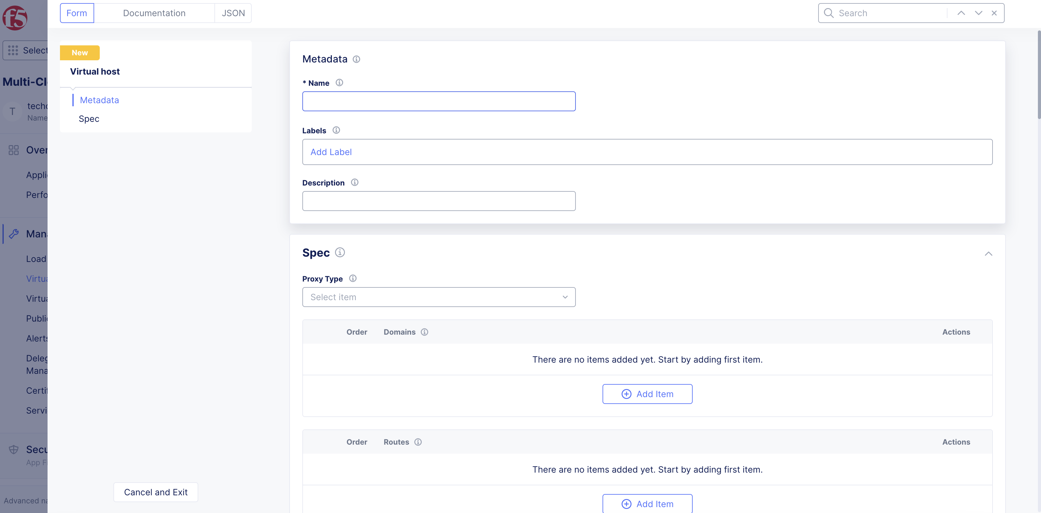
Figure: Virtual Host Configuration
Step 4: Select proxy type.
-
From the
Proxy Typedrop-down menu, select a value. See the following options:-
UDP Proxy: Installs a UDP proxy. -
Secret Management Access Proxy: Installs a Secret Management Access proxy.
-
Note: The proxy type enables you to configure specific types of proxies on the virtual host. The virtual host of the
UDP Proxytype can be monitored in theVirtual Hosts>HTTP Connect & DRPpage in your application namespace. TheUDP Proxytype does not support extensive monitoring that other types of virtual hosts support.
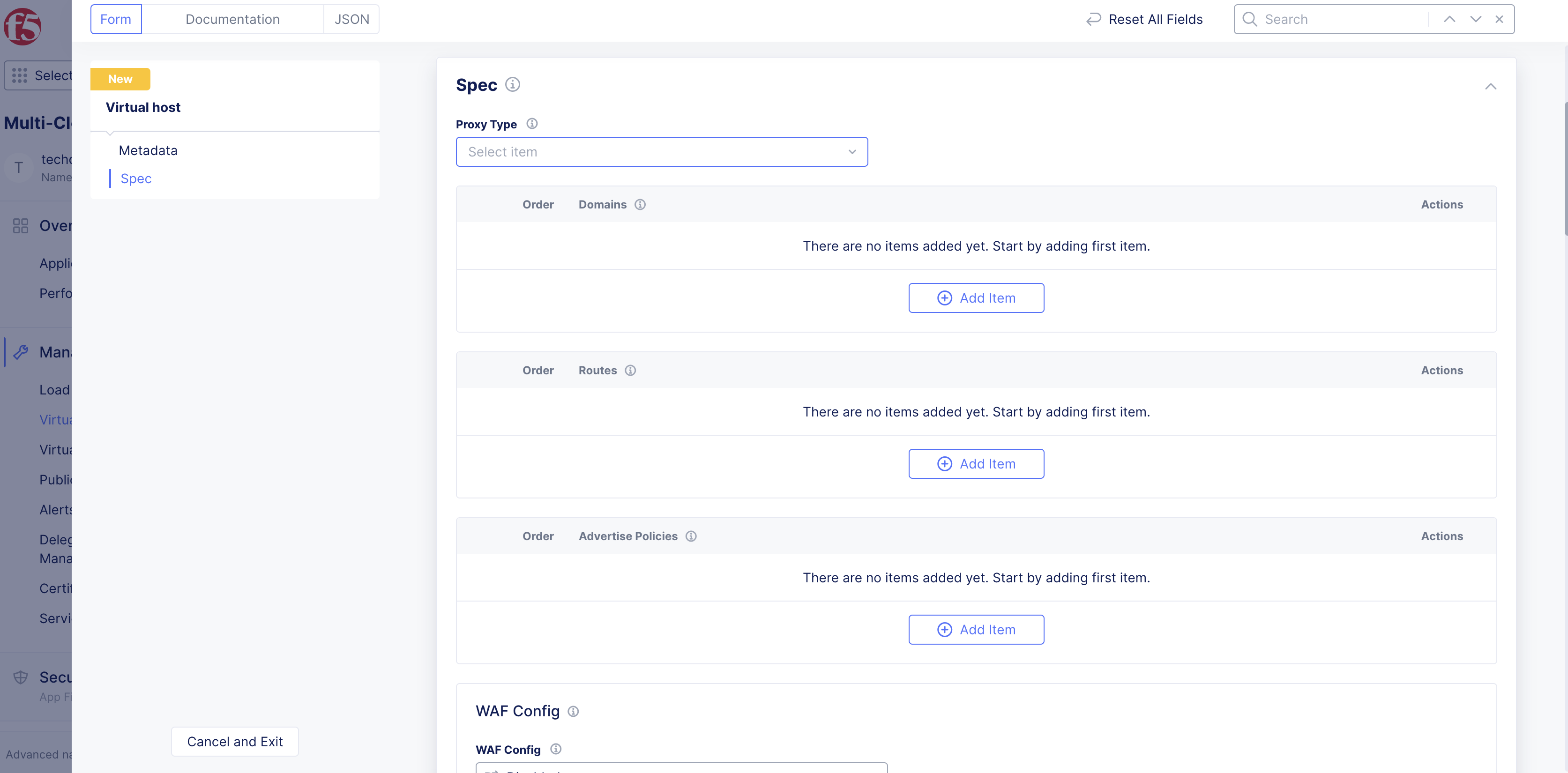
Figure: Proxy Type Options
Step 5: Add domain for the virtual host.
The domain is used to access the virtual host. A virtual host can have one or more domains associated with it.
-
Under the
Domainsbox, clickAdd item. -
Enter the domain name that the virtual host will be associated with.
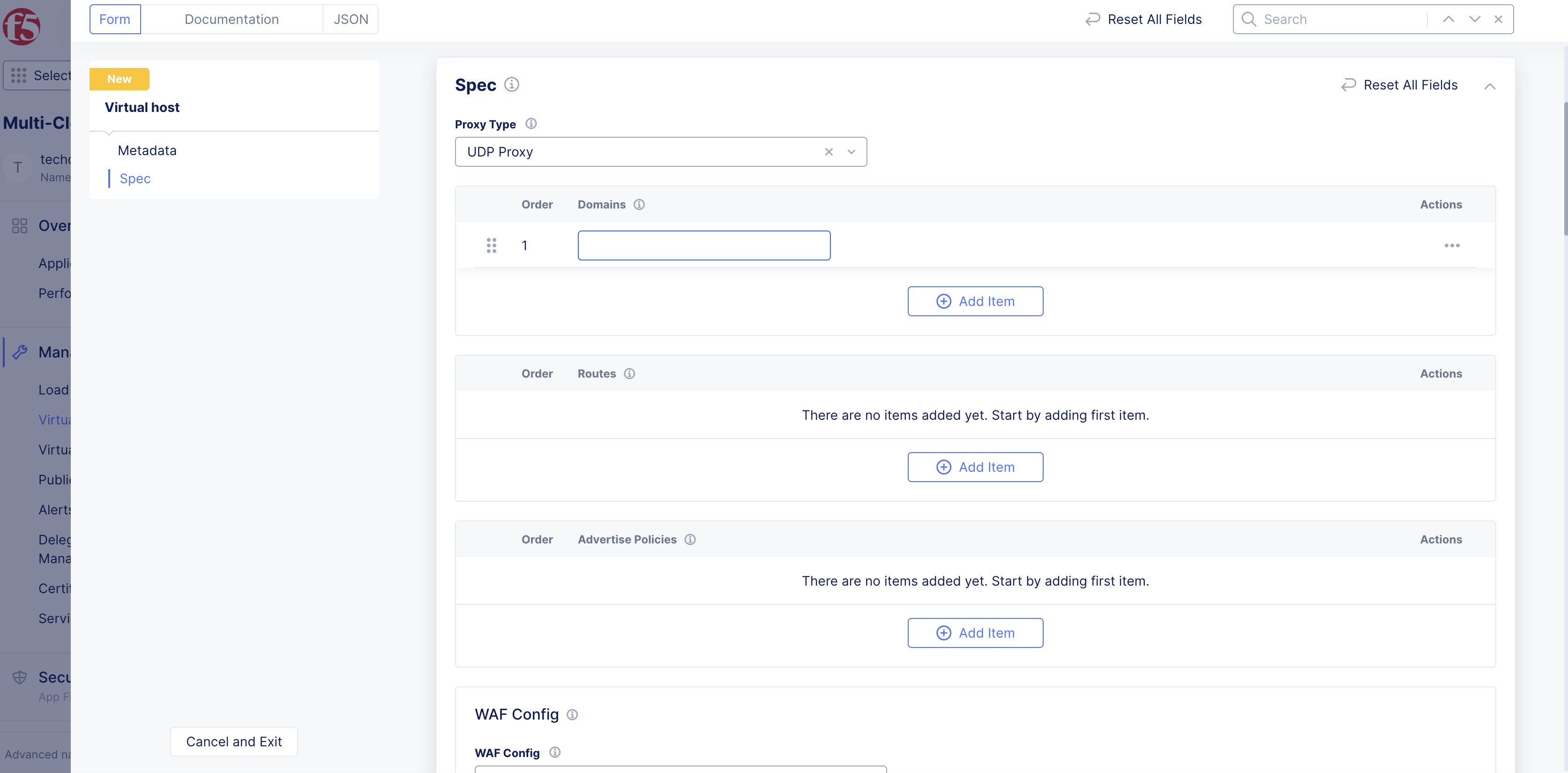
Figure: Domain Configuration
Step 6: Associate one or more routes with the virtual host.
From the Routes menu, select one or more routes to associate with the virtual host. Use Add Item to select an existing route or configure a new route.
Step 7: Select an advertise policy for the virtual host.
From the Advertise Policies menu, select an advertise policy. Use Add Item to select an existing policy or configure a new policy.
Step 8: Configure additional options.
Many include optional configurations or default configurations.
-
From the
WAF Configmenu, choose to enable a web application firewall (WAF) for your virtual host. -
Under
Dynamic Reverse Proxy, choose to configure your virtual host to resolve endpoints dynamically. -
From the
Authentication Detailsmenu, choose to configure authentication to your virtual host. -
In the
Add Request Headerssection, configure whether you want to add or remove request headers for HTTP requests. -
In the
Add Response Headerssection, configure whether you want to add or remove response headers for HTTP responses. -
Under
Buffer Policy, choose to configure a buffer policy for requests to the virtual host. -
Under
CORS Policy, choose to configure options to have the origin domain request selected resources from another server at a different origin. -
Under
Retry Policy, choose to configure the retry policy. -
Under
Compression Parameters, choose to configure the compression of dispatched data for the load balancer. -
Under
Custom Error Responses, choose to configure error codes for HTTP responses. -
From the
Select Type of Challengemenu, choose to enable a JavaScript or Captcha challenge. The default option isNo Challenge. -
From the
Total Request Timeoutmenu, configure the amount of time the server spends on the request stream before canceling the request. -
Configure all other options as needed.
Step 9: Save virtual host object.
After you finish, select Save and Exit to create the virtual host object.