Deploy and Connect CE Sites Across Multi-Cloud Networks
Objective
This quickstart guide provides instructions on how to seamlessly connect and secure applications between multiple cloud networks using F5® Distributed Cloud Mesh and F5 Distributed Cloud Console.
The steps to connect and secure applications between multiple cloud networks are:
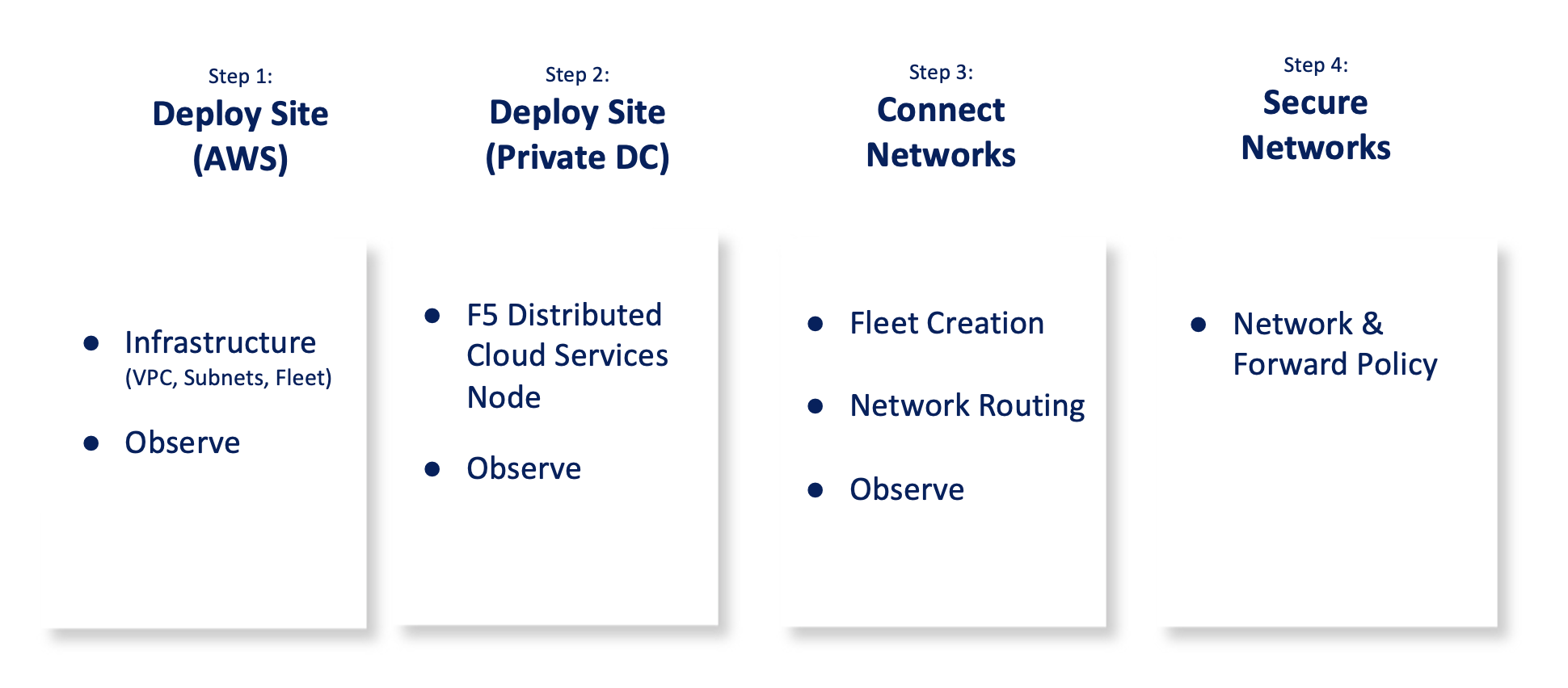
Figure: Multi-Cloud Networking and Security Set Up Steps
The following images show the topology of the example for the use case provided in this document:
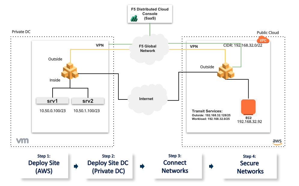
Figure: Multi-Cloud Networking and Security Sample Topology
Using the instructions provided in this guide, you can set up Amazon Virtual Private Cloud (Amazon VPC) site, data center cloud gateway, setup secure networking between the 2 clouds, and setup end-to-end monitoring.
Prerequisites
-
Distributed Cloud Console SaaS account. If you do not have an account, see Getting Started with Console.
-
Amazon Web Services (AWS) account. This is required to deploy a Site.
-
Private cloud environment (data center) with networking connectivity to the Internet and TOR from the hardware. The management IP address for your hardware is required.
Configuration
The use case provided in this guide sets up F5 Distributed Cloud Services sites as gateways for the ingress and egress traffic for the two cloud networks. The datacenter gateway site is on a physical hardware in an on-premise datacenter location. This datacenter also has TOR behind which we have VM based hosts sitting on two different subnets.
The following actions outline the activities in setting up secure networking between the AWS VPC and private data center cloud.
-
Distributed Cloud Services AWS VPC Site is deployed using the Console.
-
Distributed Cloud Services VMware site is deployed on the ESXi host using the OVA template.
-
The two cloud environments are connected using the Distributed Cloud Services global network and secured using the network policies.
-
Local-breakout for hosts on the VMware site is configured. This allows inside network hosts to access the internet using SNAT. This is achieved by configuring a Fleet and related objects - Virtual Networks, Network Interfaces, and Network Connectors on the VMware site.
Note: Ensure that you keep the Amazon Elastic IP VIPs ready for later use in configuration.
Step 1: Deploy Site (Public Cloud)
Perform the following steps to deploy a Site in your VPC:
Step 1.1: Start creating AWS VPC site object.
- Select the
Multi-Cloud Network Connectservice. - Select
Manage>Site Management>AWS VPC Sitesin the configuration menu. SelectAdd AWS VPC Site. - Enter a name for your VPC site in the metadata section.
Step 1.1.1: Configure site type selection.
- Go to the
Site Type Selectionsection and perform the following:- Select a region in the
AWS Regiondrop-down field. This example selectsus-west-2. - Select
New VPC Parametersfor theVPCfield. If you want a specific name for the AWS VPC, selectChoose VPC Namein theAWS VPC Namefield and then enter your preferred name. Otherwise, leave the drop-down selection set toAutogenerate VPC Name. Enter the CIDR in thePrimary IPv4 CIDR blocksfield. This example sets 192.168.32.0/22 as the CIDR. - Select
Ingress/Egress Gateway (Two Interface)for theSelect Ingress Gateway or Ingress/Egress Gatewayfield.
- Select a region in the
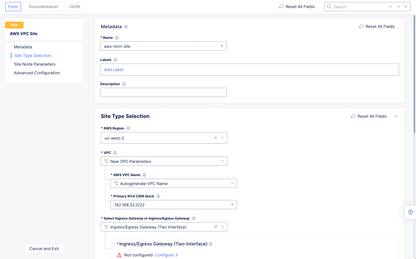
Figure: AWS VPC Site Configuration of Site Type
Step 1.1.2: Configure ingress/egress gateway nodes.
-
Select
Configureto open the two-interface node configuration wizard. -
Select
Add Itemin theIngress/Egress Gateway (two Interface) Nodes in AZsection to add theTwo Interface Node.- Select an option for the
AWS AZ namefield that matches the configuredAWS Region. This example selectsus-west-2a. - Select
New Subnetfor theWorkload Subnetfield, and then enter the subnet address in theIPv4 Subnetfield. - Similarly configure a subnet address for the
Subnet for Outside Interfacesection.
- Select an option for the
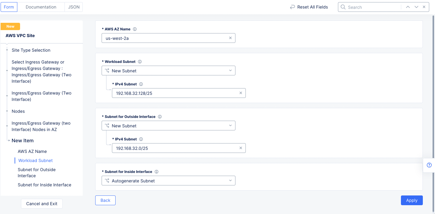
Figure: Two Interface Node Configuration
Note: This example sets 192.168.32.128/25 as the workload subnet and 192.168.32.0/25 as the outside interface subnet.
- Then select
Applyto return to the two-interface node configuration wizard.
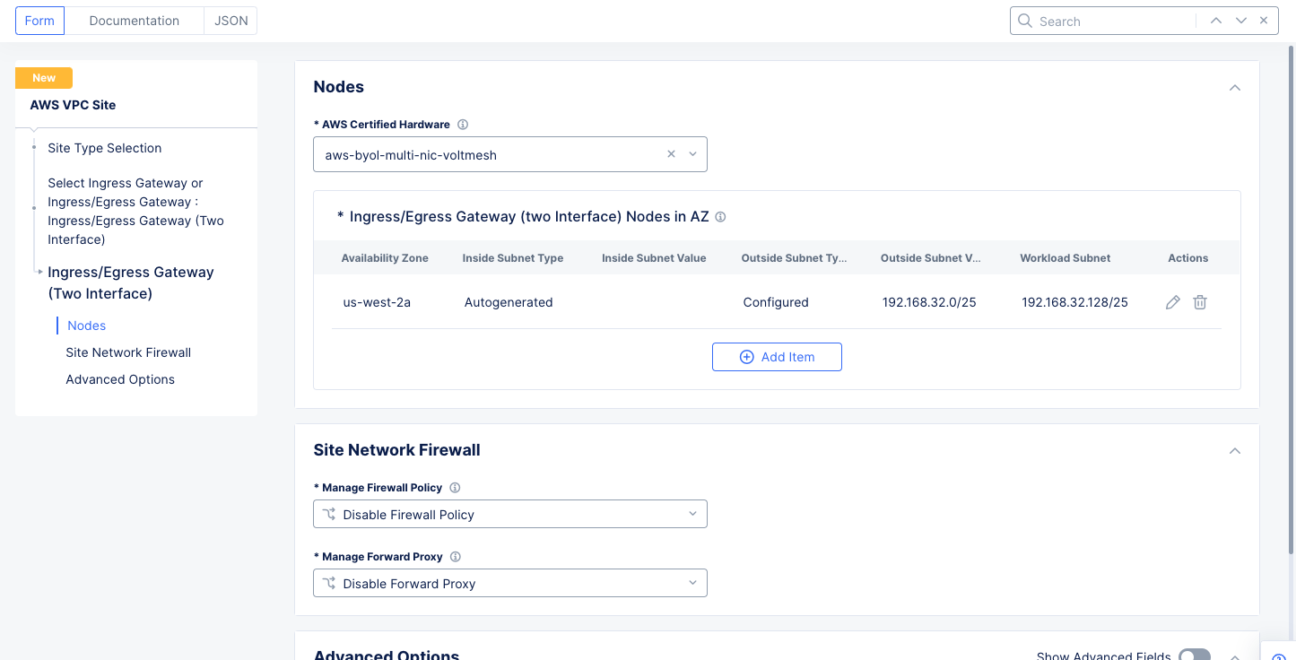
Figure: Ingress/Egress Gateway Nodes Configuration
Note: The
Site Network Firewallconfiguration will be done as part of step 4 of this quick start guide.
- Select
Applyto complete the two-interface node configuration and return to the AWS VPC site object creation.
Step 1.1.3: Complete AWS VPC site object creation.
- Select the AWS credentials object under the
Automatic Deploymentfield.
Note: Select
Add Itemin theCloud Credentialsdrop-down menu to create the credentials. You will need an AWS access key ID and AWS secret access key. See Step 1 of the guide for more information.
- Make a selection in the
AWS Instance Type for Nodefield. - Enter the public key for remote SSH if necessary.
- Select
Save and Exitto complete creating the AWS VPC object. The AWS VPC site object gets displayed.
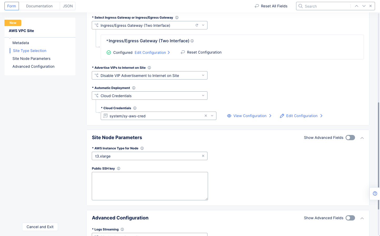
Figure: Automatic Deployment and Site Node Parameters
Step 1.2: Deploy AWS VPC site.
- Select the
Applybutton for the created AWS VPC site object. This will create the VPC site.
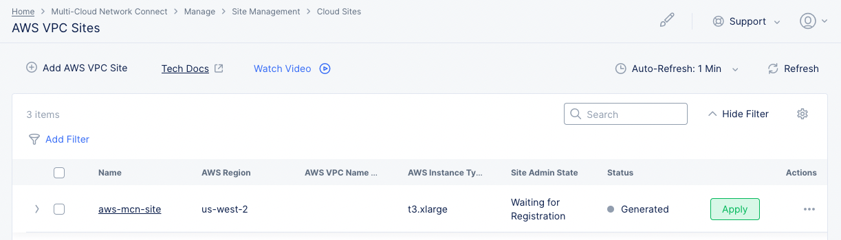
Figure: Terraform Apply for the VPC Object
- After a few minutes, select the
Refreshbutton to verify that the site is created. TheSite Admin Stateshould beOnline, and theStatusshould beApplied.
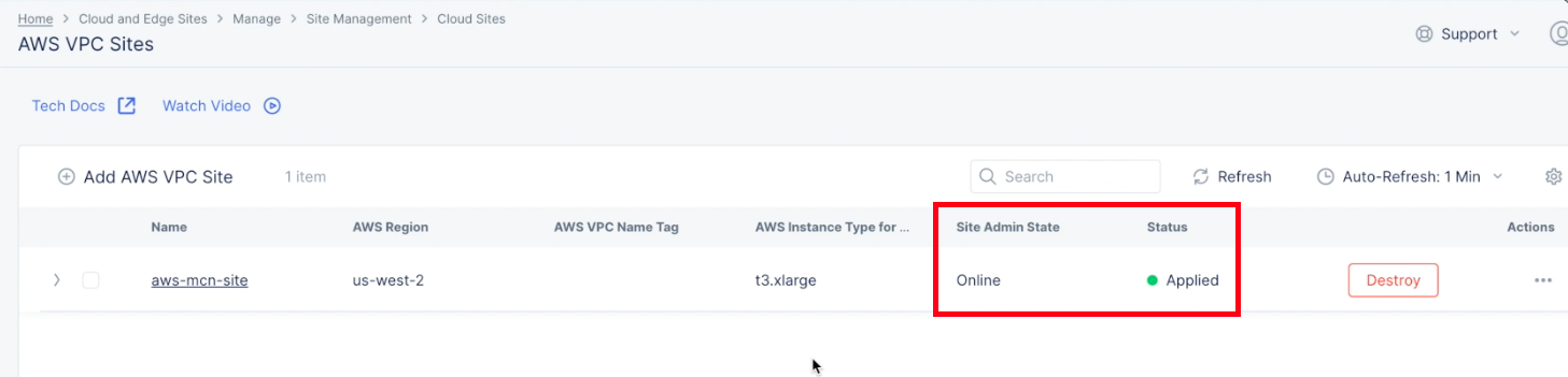
Figure: VPC Object Online
- Verify that the site is created and ready to use. Select
Sitesin the left navigation pane and then select your site from the list of sites at the bottom of theSitespage. Navigate toSite Connectivity>PoP (RE) Connectivityand hover over your newly created site to see basic health and connectivity information. - Select the site to see a slide-out panel with more details.
- Select
Explore Sitein the panel to see the site's full dashboard.
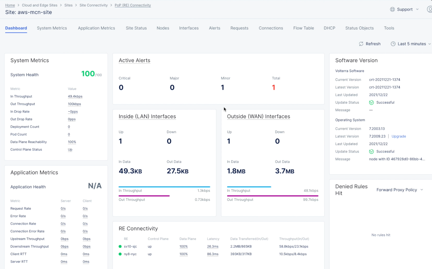
Figure: Site Dashboard and Health Details
- Select the
Interfacestab to check the interface status and details such as throughput. You can view inside and outside interfaces using theInsideandOutsideoptions.
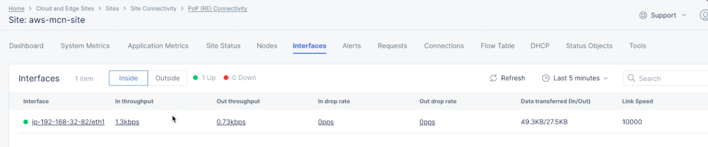
Figure: Site Dashboard Interfaces View
Step 2: Deploy Site (Private DC)
Deploying site in your private data center consists of downloading the Distributed Cloud Services site image and installing gateway site on the data center.
Note: Refer to the Prerequisites chapter for data center site deployment prerequisites.
Step 2.1: Get/Create site token.
- Log into the Console and select the
Multi-Cloud Network Connectservice. - Navigate to
Manage>Site Management>Site Tokens. - Save the site token (the value in the UID column) for use in VMware when creating a Virtual Machine (VM)
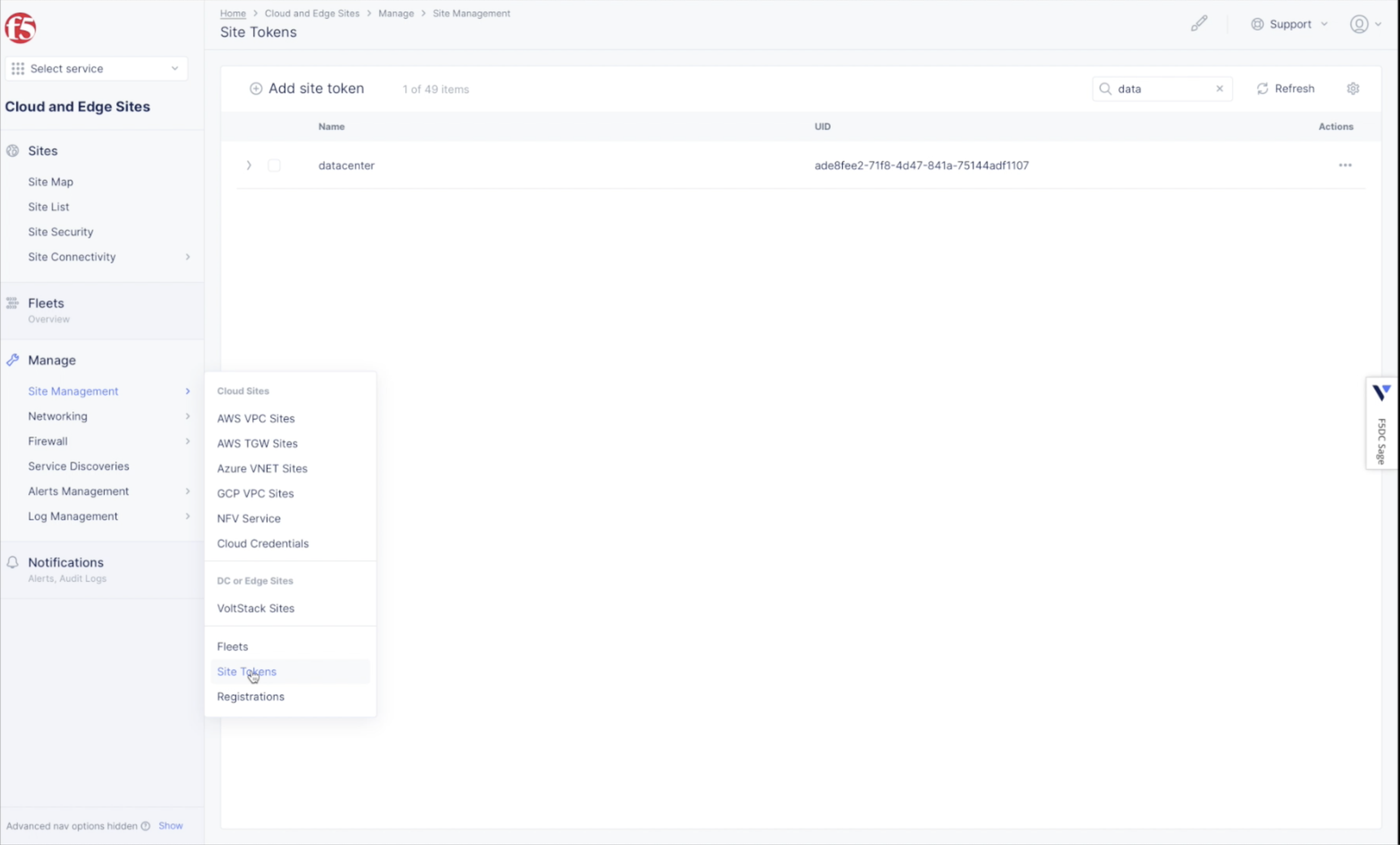
Figure: Create site token
Note: If you have not already created a site token, use
Add site tokento create a token.
Step 2.2: Download and install the VMware site image on your data center.
- See VMware Images page for downloading
OVA image.
Step 2.3: Install the VM with the OVA template.
- Log into VSphere webclient, ESXi console to create a VM from the OVA template.
- Select
Deploy a virtual machine from an OVF or OVA fileand selectNext.
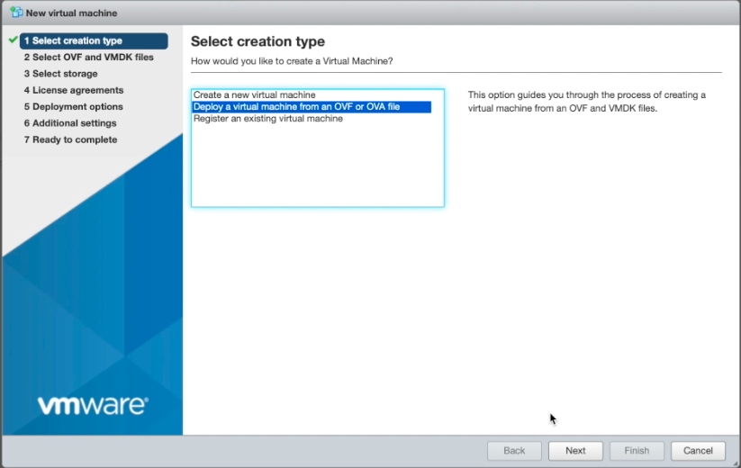
Figure: Create New VM from OVA Template
- Select OVA file:
- Enter a name for the virtual site.
- Select or drag-and-drop the OVA file.
- Select
Next.
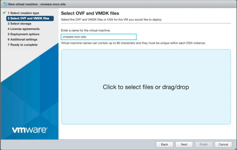
Figure: Import OVA Template
- Select an appropriate amount of storage for the VM and select
Next.
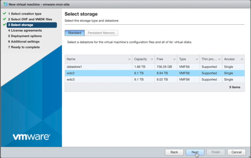
Figure: Select VM Storage
- Enter the deployment options:
- Select the
OUTSIDEandREGULAR(inside) network mappings. - Ensure that
Power on automaticallyis checked. - Press `Next'.
- Select the
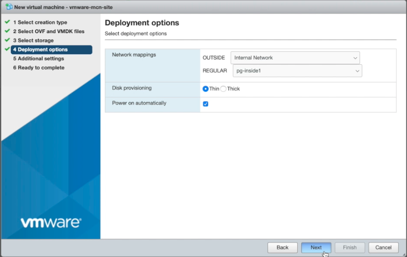
Figure: VM Deployment Options
- Enter additional settings:
- Expand the
Optionssection. - Enter the
Hostname. This should match the name of the virtual site. - Enter the token you saved from step 2.1.
- Enter the
Cluster Name, which should also match the name of the virtual site. - Enter the
Name for outside network interface. - Enter
vmware-regular-nic-voltmeshfor theCertified Hardwarefield. - Enter the
LatitudeandLongitudefor your virtual site. - Select
Next.
- Expand the
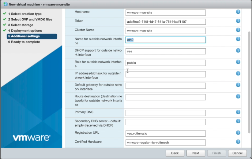
Figure: VM Deployment Options
- Validate the settings and select
Finish. The VM gets booted up.
Step 2.4: Perform site registration in Console.
- Log into the Console, select the
Multi-Cloud Network Connectservice, and navigate toManage>Site Management>Registrations. - Select
Pending Registrationstab. Find the registration request for your site and accept the registration. Validate the information shown and then select the checkbox icon. TheRegistration acceptancesliding sidebar will show information about your new VM. - Select
Save and Exit. - Wait for the registration to complete and the site to come up. You can find the site in the
Sites>Site Listview. Select your site to open the site dashboard and ensure that its health score is 100 and its interfaces are up in theInterfacestab.
Step 2.5: Create a fleet.
- In the
Multi-Cloud Network Connectservice, navigate toManage>Site Management>Fleets. - Select
Add fleet. - Enter a name for your fleet and enter a label in the
Fleet Label Valuefield. This label is later used to apply to the site.
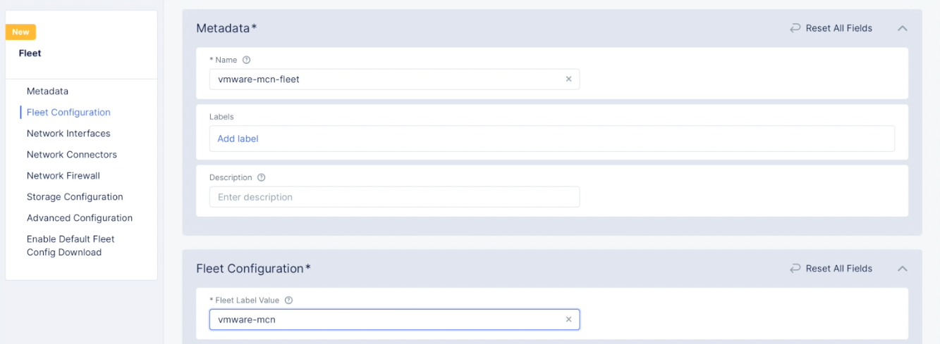
Figure: Fleet Name and Label
Step 2.5.1: Configure virtual networks.
- Use the
Outside (Site Local) Virtual Networkpull-down to see and select theAdd Itemoption. - Enter a name for your outside network and select
Site Local(Outside) Networkfor theSelect Type of Networkfield. SelectContinueto create the network and add it to the fleet configuration.
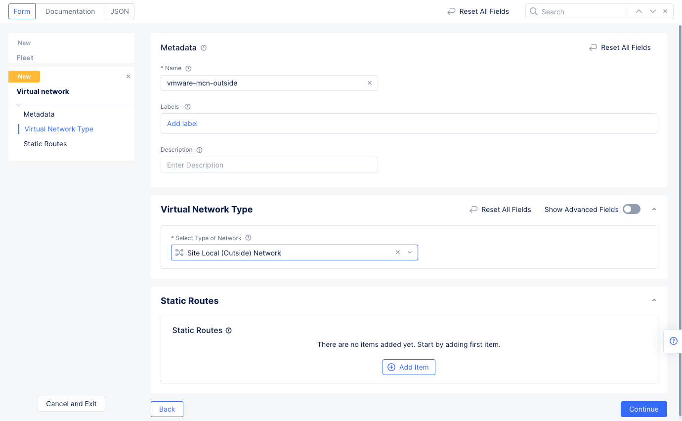
Figure: Outside Virtual Network
- In the
Fleet Configurationscreen, create the inside virtual network in the same way. SelectSelect inside virtual network objectand selectAdd Item. Enter a name for your inside network and selectSite Local Inside Networkfor theSelect Type of Networkfield. SelectContinueto create network and add to the fleet configuration.
Step 2.5.2: Configure network interfaces.
Go to the Network Interfaces section and configure the following:
- Use the
Select Interface Configpulldown to selectList of Interfaces. - Use the
List of Interfacespulldown to select theAdd Itemoption. - Enter a name for the interface, select the
Ethernet Interfacefor theInterface Typefield, and then selectConfigureto set up the Ethernet interface. - Select
eth1in theEthernet Devicefield. - Go to the
IP Configurationsection and selectDHCP Serverfor theSelect Interface Address Methodfield. SelectConfigureunder theDHCP Serveroption to open DHCP server configuration. Perform the configuration using the following guidelines:- Select
Configurein theDHCP Networkssection to open DHCP server configuration. - Enter a prefix in the
Network Prefixfield. - Select
Add Itemin theDHCP Poolssection and enter the starting and ending IP addresses. - Select
Applyat the bottom of the form to add the settings to the DHCP server configuration. This sets the DHCP pool, default gateway, and DNS server address.
- Select
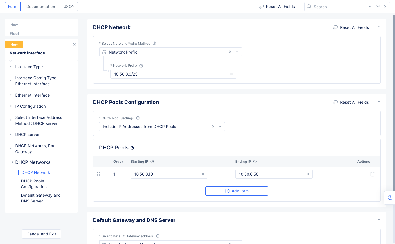
Figure: DHCP Network Configuration
- Select
Applyin theDHCP Serverconfiguration to apply the DHCP server to the Ethernet interface configuration. - Select
Site Local Network Insidein theSelect Virtual Networkfield in the Ethernet interface configuration.
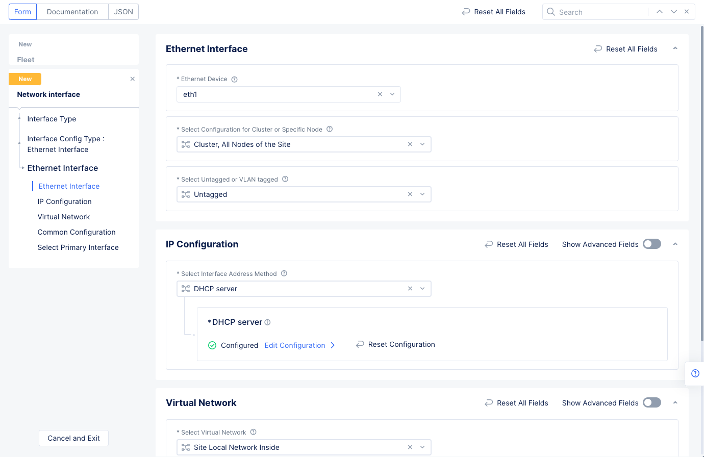
Figure: Ethernet Interface Configuration
- Select
Applyto set the ethernet interface to the network interface configuration.
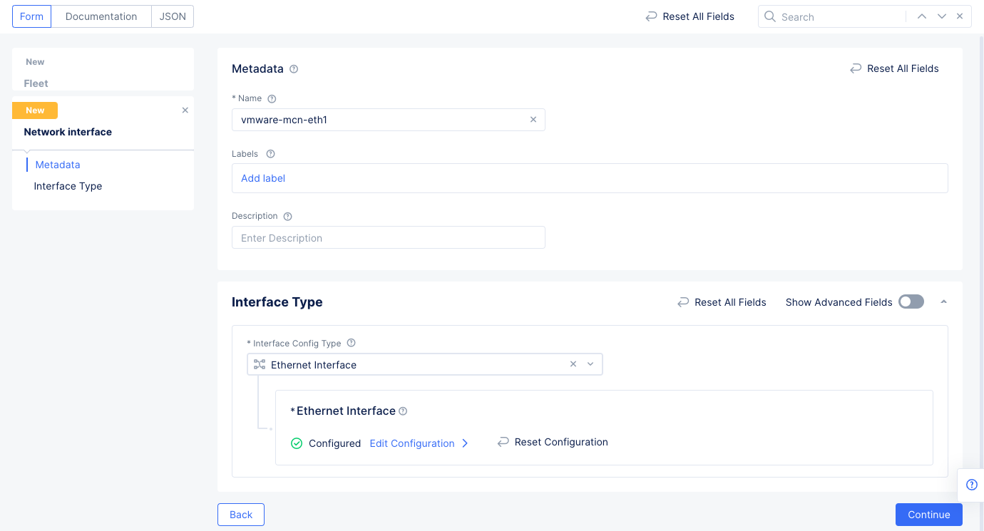
Figure: Network Interface Configuration
- Select
Continueto create and add the network interface to the fleet.
Step 2.5.3: Configure network connector and complete fleet creation.
This step creates a network connector with one in SNAT mode and the other in the direct mode to the global network.
- Select
Add Itemin theNetwork Connectorssection and then use theNetwork Connectorsdrop-down menu to selectAdd Item. - Enter a name for the network connector and select
Continueand thenSelect Network Connectorto add the network connector to the fleet. This sets the network connector to function in the default SNAT mode that connects site local inside network to site local outside network. This is used for the data center private cloud for establishing connectivity from inside subnets to outside network through the Site deployed on the VMware VM.
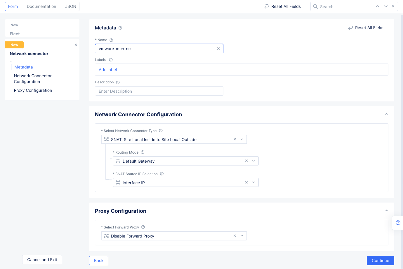
Figure: Network Connector for Private DC
- Scroll down and select
Save and Exitin the fleet configuration screen to create the fleet.
At this point, you can verify that the inside subnets can communicate with each other but accessing outside their networks is not possible. You can use ping command to verify the same.
Step 2.5.4: Add VMware site to the fleet.
- Select
Manage>Site Management>AWS VPC Sites. - Select
...>Manage Configurationfor your VMware site and then selectEdit Configurationin the upper right corner to open its configuration edit form. - Select in the
Labelsfield and addves.io/fleetwith the value of fleet label you created in previous step.
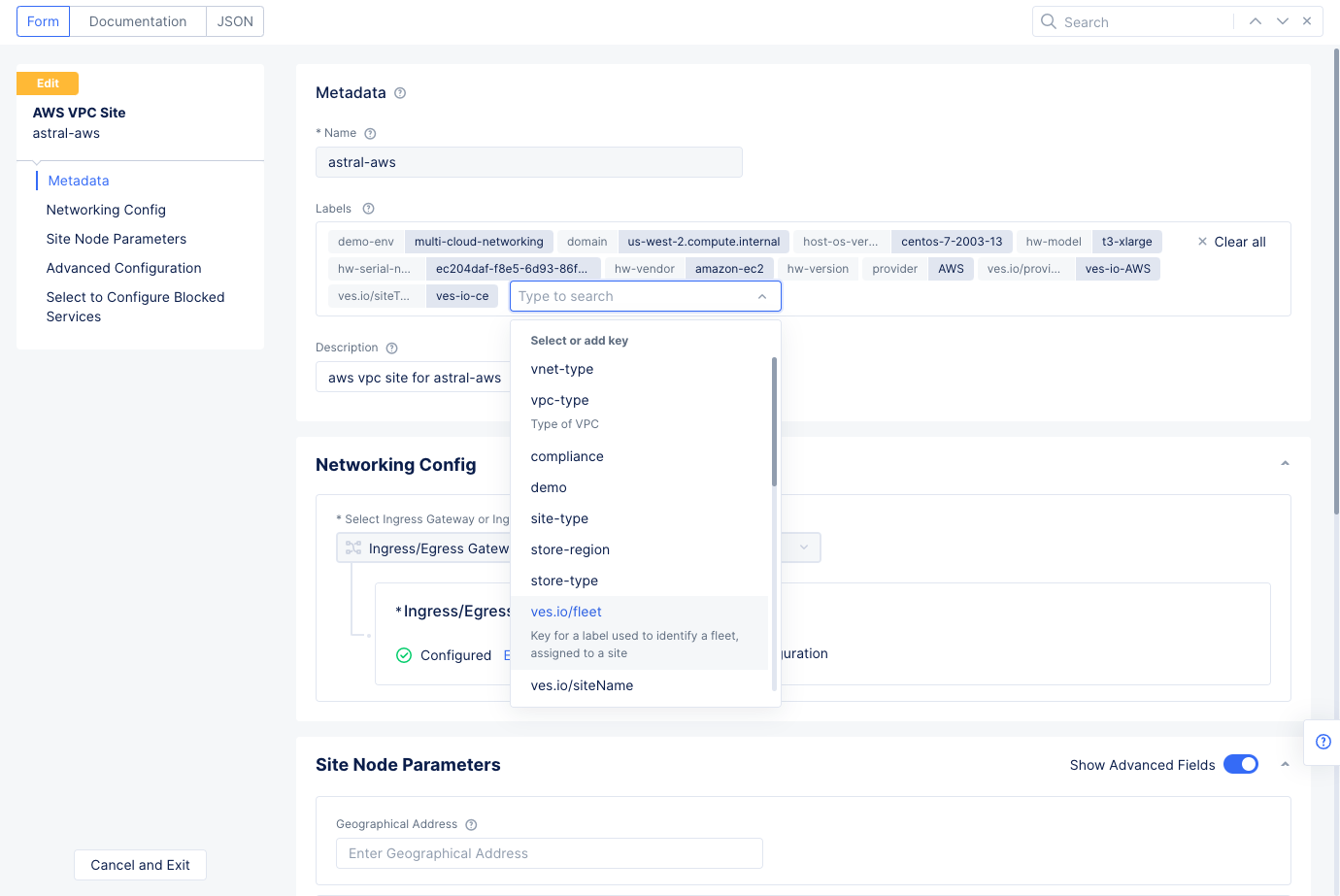
Figure: Add Fleet Label to Site
-
Select
Save and Exitto apply fleet settings to the site. -
Verify that the fleet interfaces are applied to the site. Check the site local UI dashboard for Ethernet interfaces section. The interface
Eth1gets IP address assigned by the DHCP server configured in the fleet.
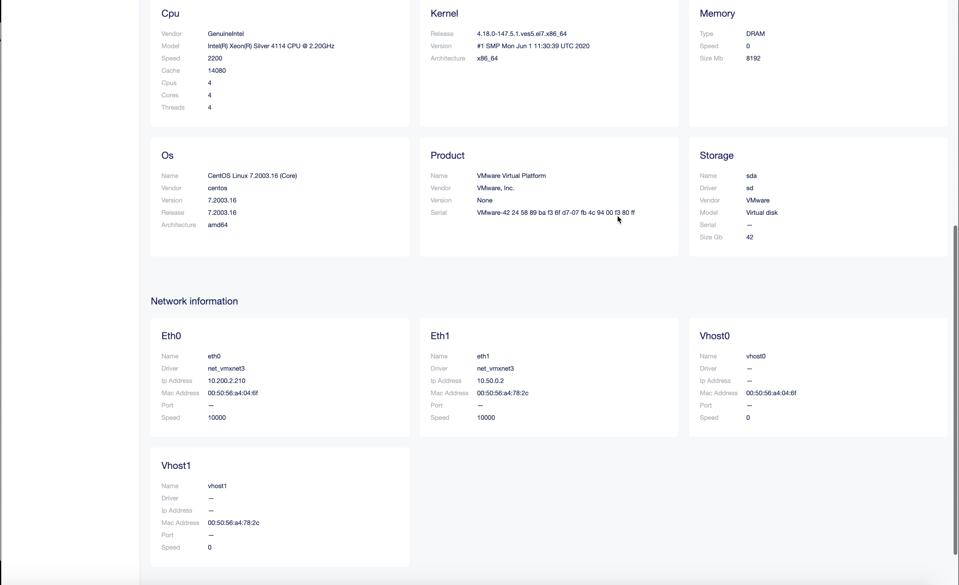
Figure: Ethernet Interface Details in Local UI Dashboard
At this point, you can verify that the inside subnets can access outside networks via the Site by means of SNAT. You can verify the same with the ping command.
Note: To check connectivity over internet, you can execute
ping 8.8.8.8to Google DNS server.
Step 3: Connect Networks
Connecting networks includes configuring local-breakout for hosts on the VMware site. That is, allowing inside network hosts to access the Internet using SNAT. This is done by configuring a Fleet and related objects - Virtual Networks, Network Interfaces, and Network Connectors. This includes creating network connectors with one in SNAT mode and other in the direct mode to the global network.
After that, connect both the VMware and AWS inside networks using Distributed Cloud Services ADN.
Perform the following to connect and secure the two cloud networks:
Step 3.1: Create global network.
- Log into the Console and select the
Multi-Cloud Network Connectservice. - Navigate to
Manage>Networking>Virtual Networksand selectAdd virtual network. - Enter a name and select
Global Networkin theSelect Type of Networkfield. - Select
Save and Exit.
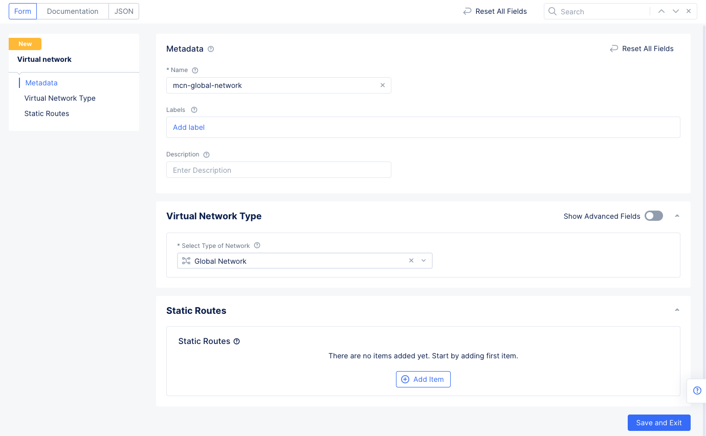
Figure: Setup Global Network
Step 3.2: Connect the global network with the VMware site.
- Navigate to
Manage>Site Management>Fleetsto see a list of your fleets. - Select
...>Manage Configurationfor the fleet you created in step 2. Then selectEdit Configurationin the upper right corner to edit the fleet. - Scroll down to the
Network Connectorssection and selectAdd Itemand then selectAdd Itemfrom the newly createdNetwork Connectorsdrop-down menu.- Enter a name for the network connector.
- Select
Direct, Site Local Inside to a Global Networkin theSelect Network Connector Typefield. - In the
Global Virtual Networkfield, select the global network you created in the previous step.
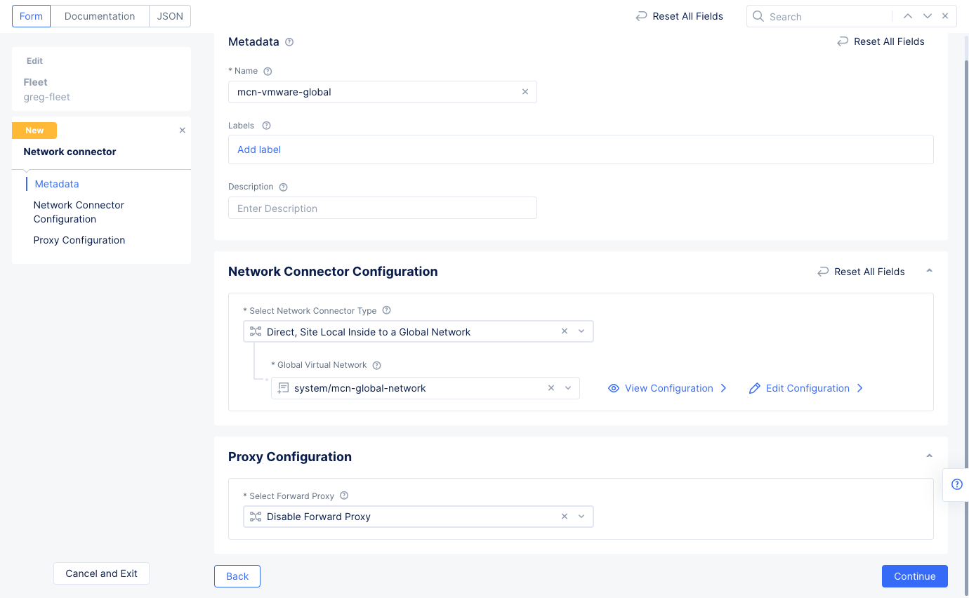
Figure: Network Connector Configuration
- Select
Continueto save the network connector and thenSave and Exitto save the updated fleet configuration.
Step 3.3: Connect the global network with the AWS VPC site.
- Navigate to
Manage>Site Management>AWS VPC Sites. - Select
...>Manage Configurationfor the site you created in step 1. Then selectEdit Configurationin the upper right corner to edit the fleet. - Scroll down to the
Networking Configsection and selectEdit ConfigurationunderIngress/Egress Gateway (Two Interface). - Select
Connect Global Networksin theSelect Global Networks to Connectfield and then selectAdd Item.- Select the global network you created previously in the
Global Virtual Networkfield. - Select
Applyto save the changes.
- Select the global network you created previously in the
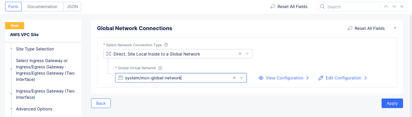
Figure: Global Network Connections
- Select
Manage Static Routesin theManage Static Routes for Inside Networkfield. - In the
List of Static Routessection, selectAdd Item.- Enter the network prefix in the
Simple Static Routefield. - Select
Add Item.
- Enter the network prefix in the
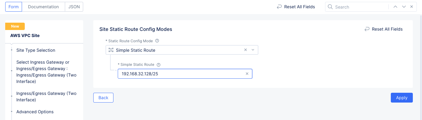
Figure: Site Static Route Configuration
- Select
Applyto add the network configuration. - Select
Applyto save the Ingress/Egress Gateway configuration. - Select
Save and Exitto save updates to the site configuration.
Now you can verify that the connectivity is enabled between the VMware subnets and the AWS cloud EC2 instances. You can use ping to verify the same.
Step 4: Secure Networks
Securing networks includes applying firewall policies to restrict the network accesses for chosen networks. It also includes applying forward proxy policies to allow access to chosen URLs. This is achieved by means of creating a network firewall with the policies and applying to the fleet.
This example creates a firewall policy that allows access only from one subnet of the private DC to the AWS cloud and blocks access for all other subnets. It also creates a forward proxy policy that blocks access to a specific domain and allows everything else.
Perform the following steps to set up secure networks.
Step 4.1: Create and add network firewall to the fleet.
- Log into the Console and select the
Multi-Cloud Network Connectservice. - Select
Manage>Site Management>Fleets. Find your fleet from the displayed list and select...>Manage Configurationto open its configuration form, and then selectEdit Configurationin the upper right. - Scroll down to the
Network Firewallsection and use theNetwork Firewallpull-down menu to selectAdd Item. Enter a name for the firewall.
Step 4.1.1: Create and add firewall policies to the fleet.
- Scroll down to the
Firewall Policysection and selectActive Firewall Policies. Use theSelect Itempull-down menu and selectAdd Item. This policy will allow all traffic for the server1 prefix.
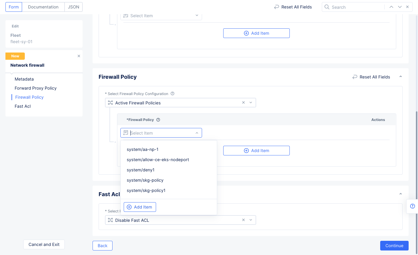
Figure: Network and Policy for Network Firewall
-
Enter a name for the policy and add the prefix of the server1 subnet (for which you want to allow access) in the
IPv4 Prefix Listfield. -
Select
Configureon theConnections From Policy Endpointssection to configure an egress rule. SelectAdd Itemto create the egress rule.- Set a name for the egress rule and select
Allowfor theActionfield. - Select
Applyto add the egress rule to the list of egress rules.
- Set a name for the egress rule and select
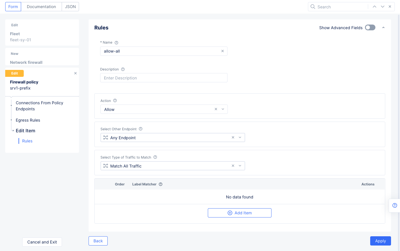
Figure: Egress Allow Rules
- Select
Applyto save the egress rules list. - Select
Continueto save the server1 firewall policy
-
Select
Add itemin theFirewall policysection to add another policy for the server2 prefix. This one will deny access to a subnet. -
Select the
Select Itemfield and selectAdd Item. -
Enter a name for the policy and add the prefix of the server2 subnet (for which you want to block access) in the
IPv4 Prefix Listfield. -
Select
Configureon theConnections From Policy Endpointssection to configure an egress rule. SelectAdd Itemto create the egress rule that denies traffic to a subnet.- Set a name for the egress rule and leave
Denyfor theActionfield. - Select
List IP Prefix Setin theSelect Other Endpointfield. - Select in the reference field and then select
Add Item. - Enter a name for the prefix set, enter the subnet prefix, and press
Continue. - Select
Applyto add the egress rule to the list of egress rules.
- Set a name for the egress rule and leave
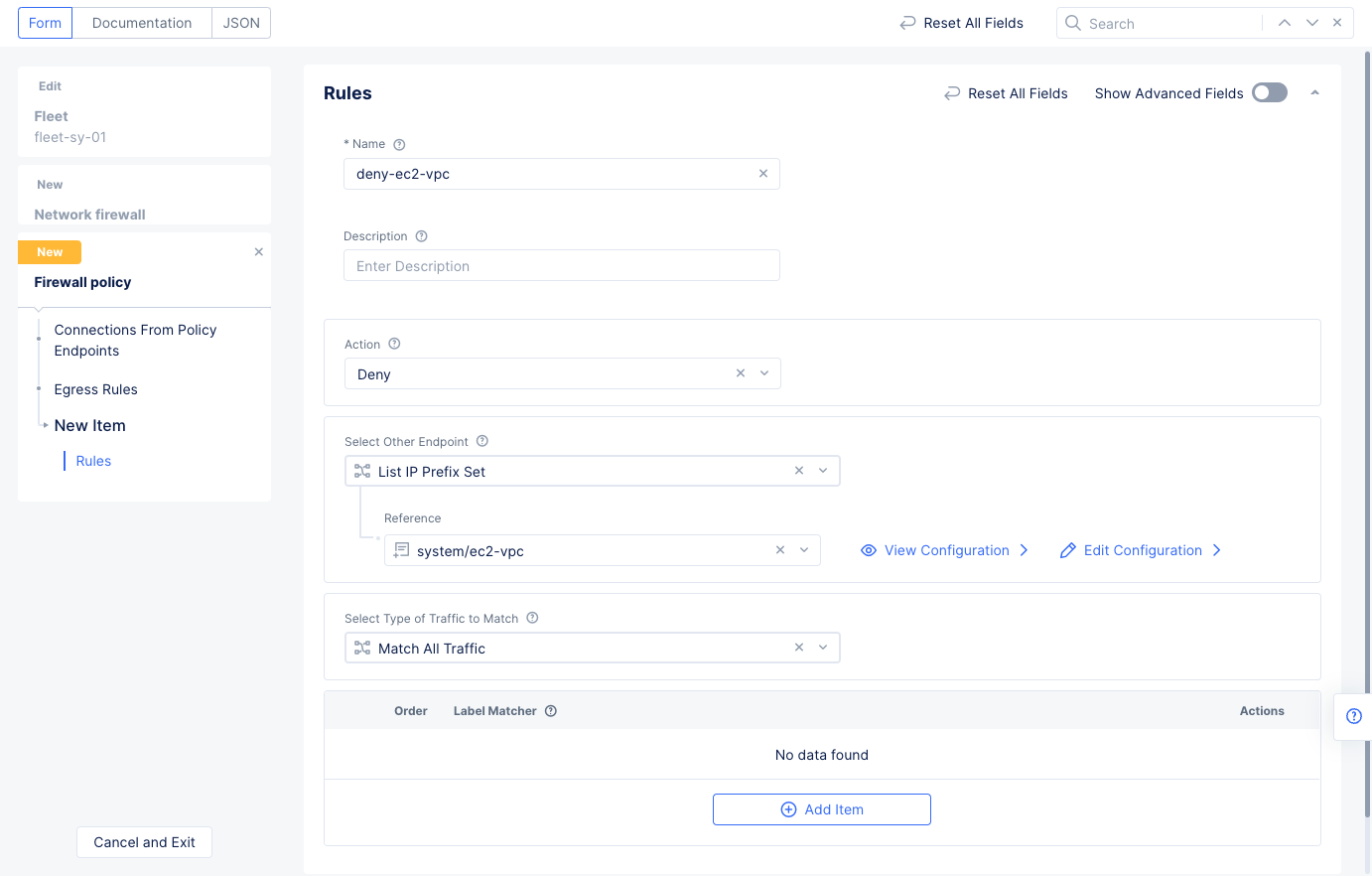
Figure: Egress Deny Rule for a Subnet
- Select
Add Itemto create a second egress rule that allows all other traffic.- Set a name for the egress rule and select
Allowfor theActionfield. - Select
Add itemto add the egress rule to the list of egress rules.
- Set a name for the egress rule and select
- Select
Applyto save the egress rule list, and selectContinueto complete the server2 policy.
- Select
Add Itemto add a third policy slot for the local internet breakout. Then use theSelect Itempull-down menu to selectAdd Item. - Enter a name for the new firewall policy.
- Select
Any Endpointfor theEndpoint(s)field in thePolicy For Endpointssection. - Select
Configureon theConnections To Policy Endpointssection to configure an ingress rule that allows all traffic, and then selectAdd Itemto create the ingress rule.- Enter a name for the ingress rule.
- Select
Allowfor theActionfield. - Select
Applyto add the ingress rule to the list of ingress rules. - Select
Applyto add the list to the network policy.
- Select
Configureon theConnections From Policy Endpointssection to configure an egress rule for this network policy, and then selectAdd Itemto create the egress rule.- Set a name for the egress rule.
- Select
Allowfor theActionfield. - Select
Applyto add the egress rule to the list of egress rules.
- Select
Applyto save the egress rule list, selectContinueto complete the third firewall policy, selectContinueto add the network firewall to the fleet configuration, and finally selectSave and Exitin the fleet configuration to save changes to fleet.
Step 4.1.2: Verify the policy operation.
-
Verify that access from only one subnet is allowed to the EC2 instances of AWS. Also, verify that the site local breakout and internet access is still allowed. Enter
pingcommand to an EC2 instance IP address from both subnets and only one is allowed. -
You can also verify the policy and rule hits from Console. Navigate to
Manage>Firewall>Firewall Policies. Check theHitsfield for your policy.
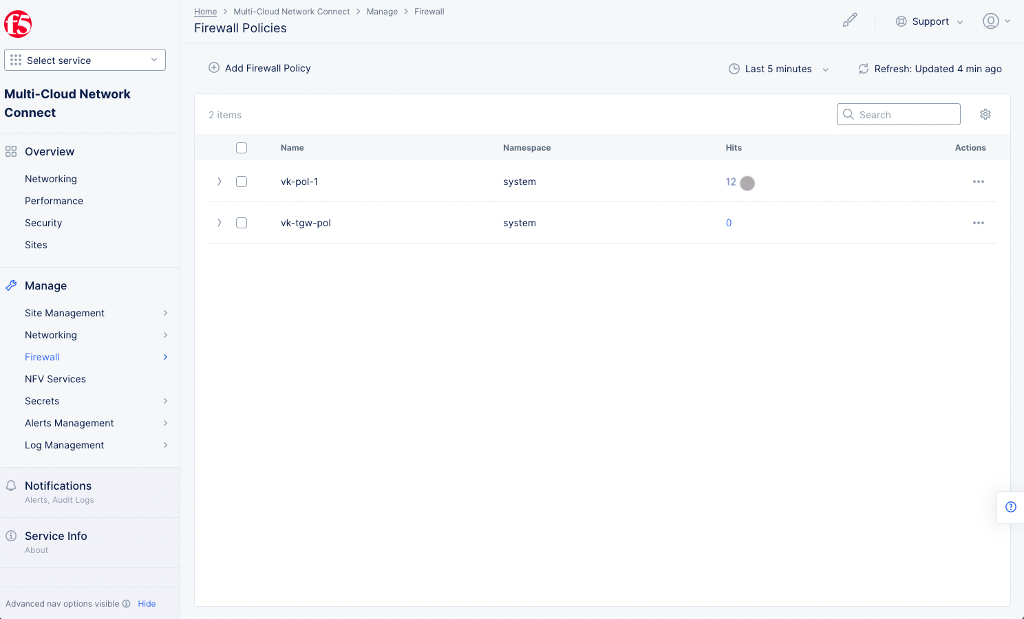
Figure: Policy Hits
- Select the value in the
Hitscolumn for your policy to view the rule hits.
Step 4.2: Add a forward proxy rule that blocks a specific URL.
To enable URL filtering, update the firewall created in step 4.1.
- Go to
Manage>Firewall>Network Firewalls. - Select
...>Manage Configurationfor the firewall created earlier, and then selectEdit Configuration. - Scroll down to
Forward Proxy Policyand selectActive Forward Proxy Policies. - Use the
Select Itempull-down menu to selectCreate new Forward Proxy Policy.- Enter a name for the new policy.
- Select
All forward Proxies on Sitein theProxysection so that it gets activated everywhere. - Select
Denied connectionsin theRulessection. - Select
Add Itemin theTLS Domainssection, enter the URL you wish to block in theExact Valuefield, and selectApplyto add this URL to your denied TLS domains.
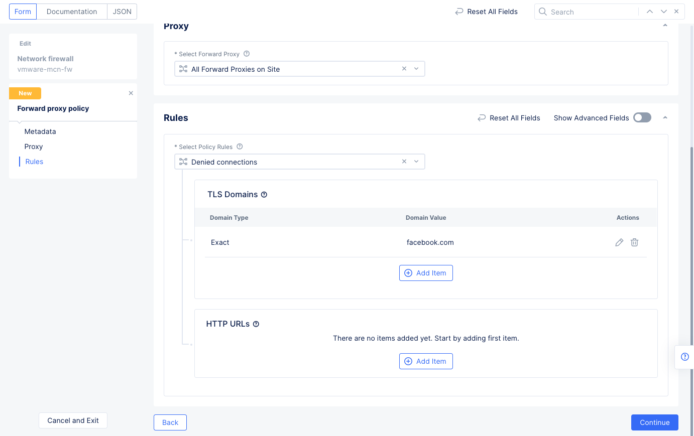
Figure: Enable Forward Proxy for facebook.com
- Select
Continueand thenSave and Exitto save the changes to your firewall.
Step 4.3: Enable forward proxy for network connector of the private DC.
- Go to
Manage>Networking>Network Connectors. Select...>Manage Configurationfor the VMware site network connector you created, and then selectEdit Configuration.
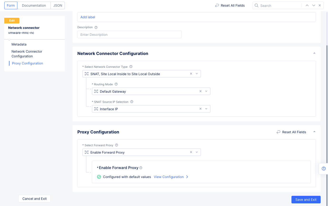
Figure: Enable Forward Proxy for VMware Networks
- Select
Enable Forward Proxyfor theSelect Forward Proxyfield. SelectSave and Exit.
This is required to apply the forward proxy policies.