Create Secure Edge Networks
Objective
This quickstart guide provides instructions on how to create secure edge networks using F5® Distributed Cloud Console and F5 Distributed Cloud Mesh.
The steps to create secure edge networks are:
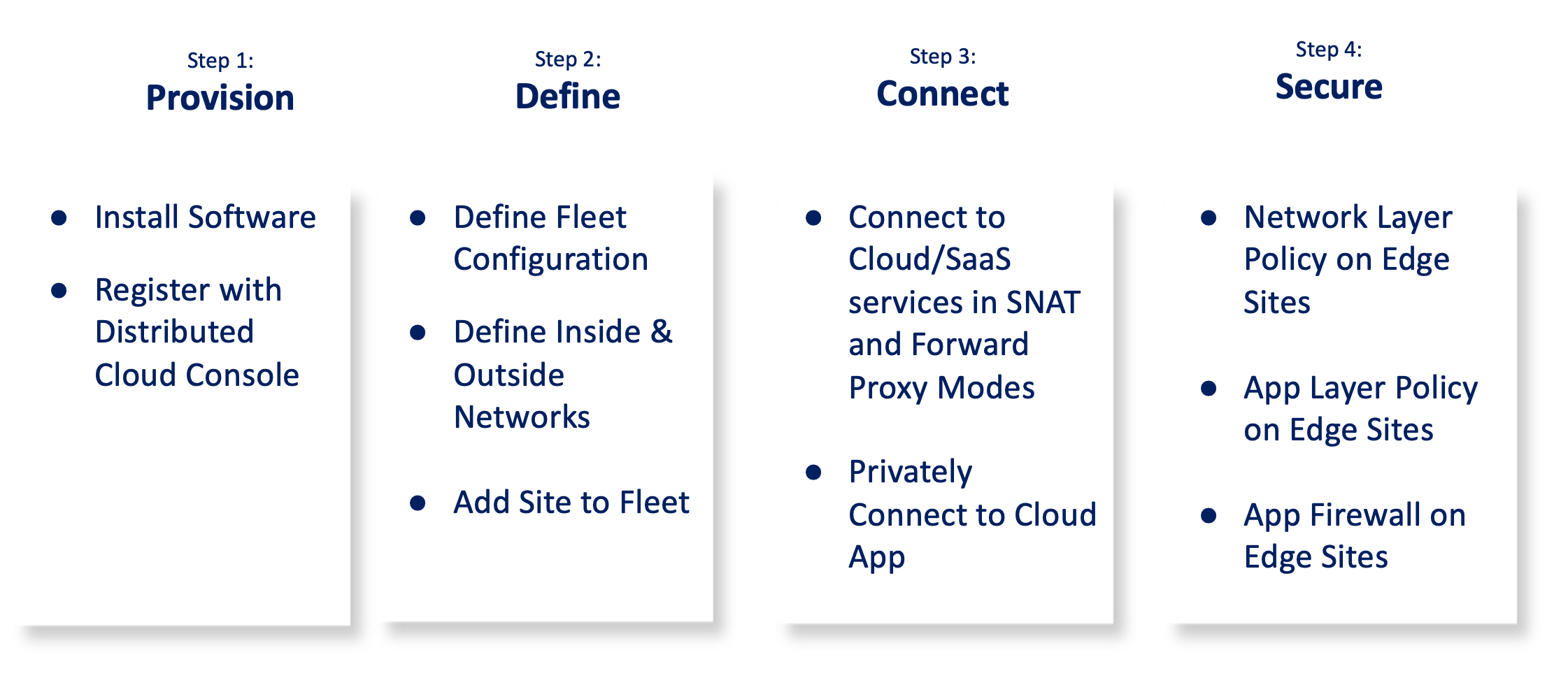
Figure: Steps to Deploy Edge Cloud Networking and Security
The following image shows the topology of the example for the use case:
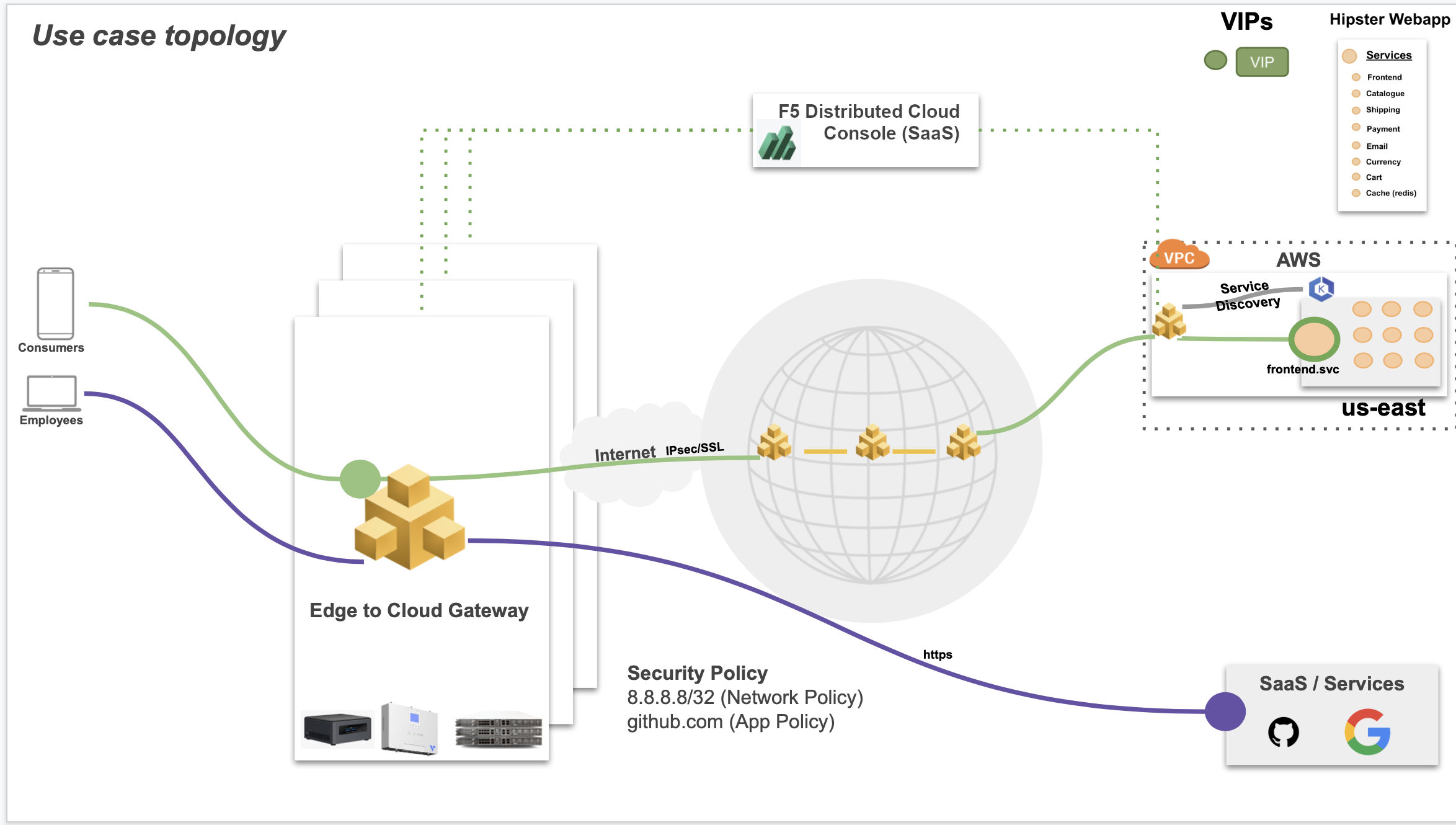
Figure: Sample Topology
Using the instructions provided in this guide, you can deploy an F5 Distributed Cloud Site as part of a fleet, connect it to the cloud or SaaS services over the public Internet or privately, and secure the Distributed Cloud Site using network policies, service policies, and application firewall.
Prerequisites
-
Distributed Cloud Console account. If you do not have an account, see Getting Started with Console.
-
Amazon Web Services (AWS) account. This is required to deploy a CE Site.
-
Intel Next Unit of Computing (NUC) commodity device with at least 4 vCPUs and 8 GB RAM. See Supported Hardware section.
-
Distributed Cloud Services
vesctlCLI utility. See vesctl for more information. -
Docker.
-
The balenaEtcher software to flash the F5 Distributed Cloud Services software image on to a USB drive.
-
A secret and policy document for encrypting your certificates and secrets using F5 Distributed Cloud Blindfold. See the Blindfold TLS Certificates guide for more information.
-
Self-signed or CA-signed certificate for your application domain.
Configuration
The use case provided in this guide sets up a Site on a commodity edge device and adds it to a fleet. The Site is then connected to cloud or SaaS services and secured using the Distributed Cloud Services security features.
The following list outlines the sequence of activities performed for this use case:
-
Distributed Cloud Services software is installed on the edge device and registered on F5 Distributed Cloud Console.
-
A fleet is created with the required network configurations, and a fleet label is applied to the Site to make it part of the fleet.
-
The edge Site is connected to cloud or SaaS services over the public Internet in the
Default Gateway SNAT ModeorForward Proxy Mode. The step also shows how to privately connect the edge Site to cloud apps, without exposing communication to the internet. -
Network policy to allowlist access to specific IP addresses and service policy to allowlist or denylist access to specific URLs is configured. Also, the application firewall is applied to block sophisticated application layer attacks, such as the SQL injection attack.
The use case for this document assumes that an application called as "Hipster Webapp" is deployed in an AWS VPC using AWS EKS. Also, a Distributed Cloud Mesh node is deployed in the same VPC with the Site name as hipster-webapp-west. The K8s namespace name is hipster.
The application consists of the following services:
- frontend
- cartservice
- productcatalogservice
- currencyservice
- paymentservice
- shippingservice
- emailservice
- checkoutservice
- recommendationservice
- adservice
- cache
Note: Ensure that you keep the Amazon Elastic IP VIPs ready for later use in configuration.
Step 1: Provision
You can use any of the supported hardware devices. However, in case of F5 Volterra IGW or ISV devices, the software is pre-installed, and you can power on, connect through Ethernet or Wi-Fi, and perform registration.
Perform the following steps to provision the Site on the commodity device:
Step 1.1: Download the Distributed Cloud Services software image.
Download the certified hardware image from the certified images page.
Step 1.2: Create a site token.
Log into Distributed Cloud Console and create a site token as per the instructions in the CE Deployment guides.
Note: You can also use an existing site token. In case you do not have any token, create one for using later for registration.
Step 1.3: Install the software on the device.
-
Install the Distributed Cloud Services software using the downloaded image on the commodity device as per the instructions in the Create Baremetal Site guide.
-
Log into your device terminal and perform initial configuration. Initial configuration includes setting site token, cluster name, and set default values for rest of the options, such as network configuration.
Step 1.4: Perform Site registration.
-
Log into Console and select the
Multi-Cloud Network Connectworkspace. -
Select
Managefrom the configuration menu andSite Management>Registrationsin the options. -
Click
Pending Registrationstab and find the registration request for your device. ClickApprove. -
Click
Acceptto confirm.
Note: Check for your device status in the
Other Registrationstab. TheONLINEstatus indicates that the Site is provisioned and ready to use.
Step 1.5: Deploy web application and node in the Amazon VPC.
Perform the steps in Step 1: Deploy Site. This step performs automatic Site registration.
Step 2: Define
Create a fleet of Sites with inside and outside network configuration and add the Site created in the previous section to this fleet.
Step 2.1: Log into Console and create network configuration required for fleet.
Create virtual networks and network interfaces for the inside and outside networks. Also, create a network connector for connecting inside network with outside network.
Step 2.1.1: Create outside and inside networks.
- Select
Managein the configuration menu andNetworking>Virtual Networksin the options. ClickAdd virtual network. - Enter a name for your network and select
Site Local Networkfor theNetwork Typefield. - Click
Add subnet, enter an IP address for thePrefixfield, and enter prefix length for thePrefix Lengthfield. ClickApplyto add subnet. - Click
Add virtual networkto create the virtual network.
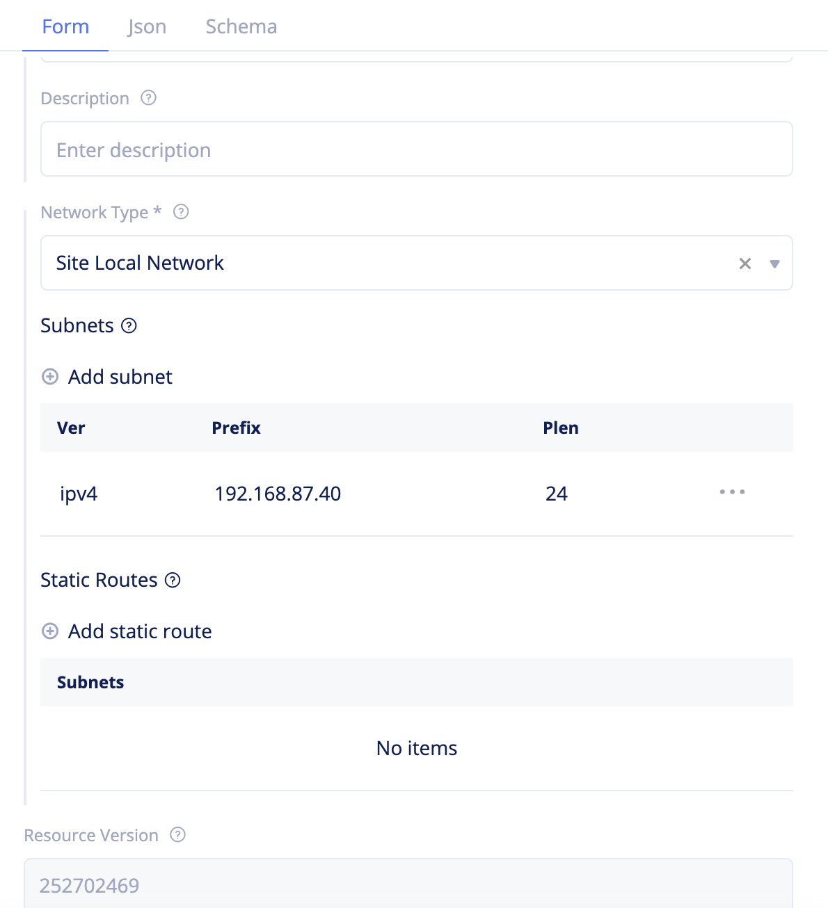
Figure: Virtual Network Creation
- Repeat the above steps to create another network with the
Network TypeasSite Local Inside Network.
Step 2.1.2: Create outside and inside network interfaces.
- Select
Managein the configuration menu andNetworking>Network Interfacesin the options. ClickAdd network interface. - Enter a name for your network interface, set
Ethernetfor theTypefield, and seteth0for theDevice Namefield. - Click
Select Virtual Network, select the outside network created in the previous step and clickSelect Virtual Networkto apply the virtual network. - Select
Enablefor theEnable DHCP Clientfield. - Select
Disable DHCP Serverfor theEnable DHCP Serverfield. - Click
Add network interfaceto complete creating the network interface.
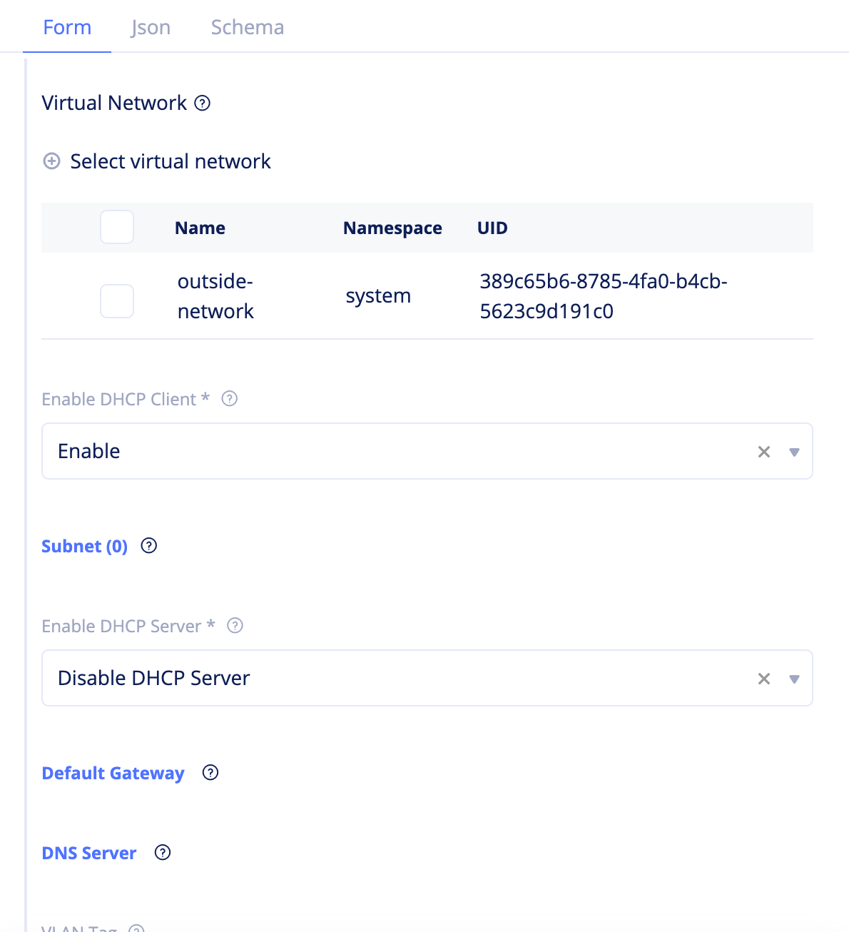
Figure: Network Interface Creation
- Repeat the above steps to create another network interface with the following configuration:
- Set
Ethernetfor theTypefield and seteth1for theDevice Namefield. - Click
Select Virtual Network, select the inside network created in the previous step and clickSelect Virtual Networkto apply the virtual network. - Select
Disablefor theEnable DHCP Clientfield. - Select
Enable DHCP Serverfor theEnable DHCP Serverfield.
- Set
Step 2.1.3: Create network connector.
- Select
Managein the configuration menu andNetworking>Network Connectorsin the options. - Click
Add network connector. - Enter a name for your network and select
Default Gateway Snatfor theNetwork Connector Typefield. - Select
Site Local Networkfor theOutside Virtual Network Typefield. - Click
Select outside networkand select the outside network created in Step 2.1.1. - Select
Site Local Inside Networkfor theInside Virtual Network Typefield. - Click
Select inside networkand select the inside network in Step 2.1.1. - Click
Add network connectorto complete creating the network connector.
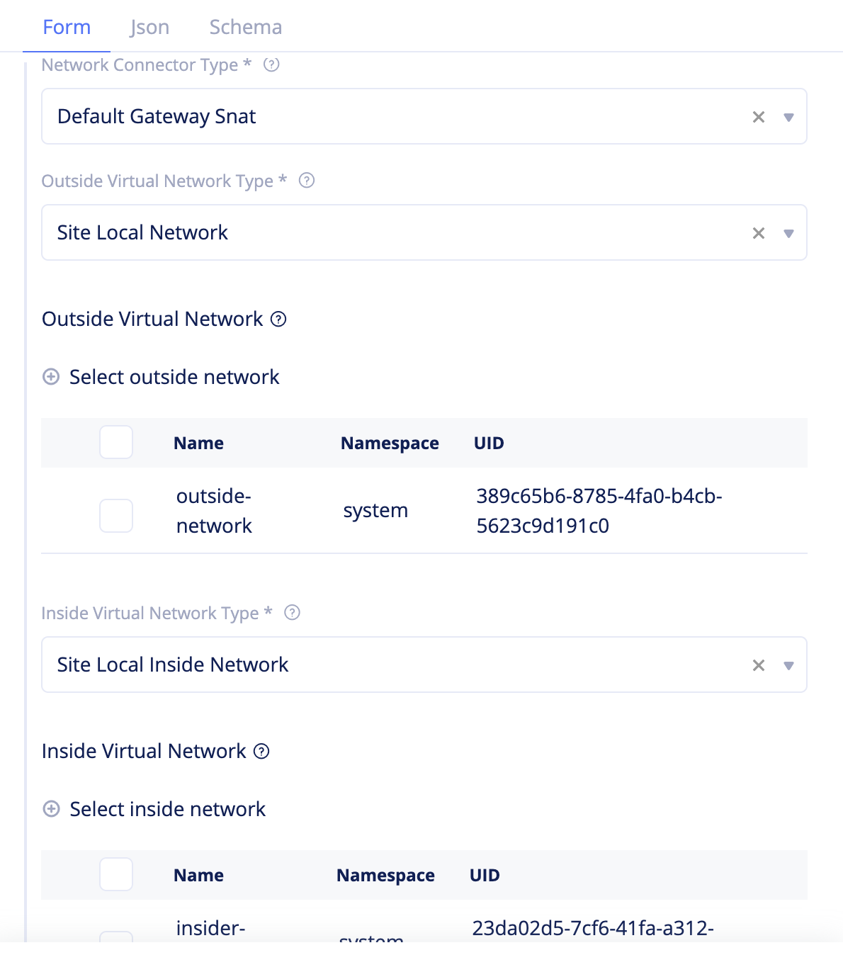
Figure: Network Connector Creation
Step 2.2: Start creating a fleet.
- Navigate to the
Managein the configuration menu andFleetsin the options. ClickAdd fleetto load fleet creation form. - Enter a name for your fleet and set a label in the
Fleet Label Valuefield.
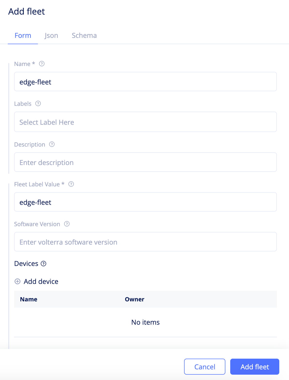
Figure: Fleet Basic Configuration
Step 2.3: Configure network settings.
Step 2.3.1: Add outside and inside network interfaces to the fleet.
- Click
Add deviceand set a name for theDevice Namefield. - Select
Owner VERandNetworking Devicefor theDevice OwnerandDevice Instancefields respectively. - Click
Select Interfaceand select the outside network interface created in Step 2.1.2. - Select
Outside Interfacefor theUsefield and clickApplyto add the device to fleet.
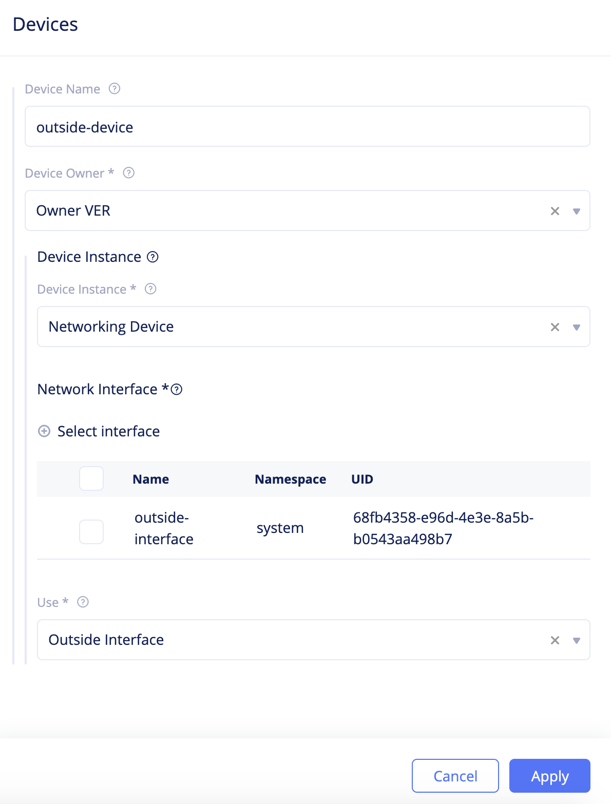
Figure: Fleet Network Interface Configuration
- Repeat the above steps to add the inside network interface created in Step 2.1.2. Select
Inside Interfacefor theUsefield.
Step 2.3.2: Add network connector to the fleet.
Click Select network connector and add the network connector created in Step 2.1.3.
Step 2.4: Complete fleet creation.
Click Add fleet to complete fleet creation.
Step 2.5: Add Site to the fleet.
- Select
Sitesfrom configuration menu andSite Listfrom options. - Click
...>Editto open Site edit form. - Click in the
Labelsfield and selectves.io/fleetas the label. - Select the value as the label of the fleet you created in Step 2.2.
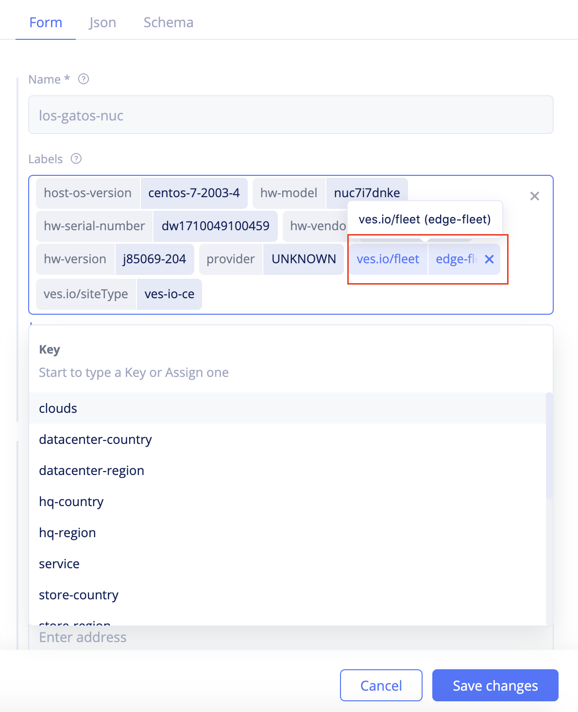
Figure: Add Fleet Label to Site
- Click
Save changesto add your Site to the fleet.
Step 3: Connect
Connect privately to cloud application that is not exposed on the public Internet. This use case has the cloud app and hipster-shop that are already deployed in AWS EKS. The users on the edge Site need to reach frontend service over a private connection without exposing frontend to the internet. This is achieved by deploying a Mesh node in the same VPC where the hipster-shop is deployed, setting up service discovery, and configuring load balancer for the frontend service.
Note: This section provides the details for configuring the required components for the load balancer. For detailed instructions on creation of virtual host, see Create and Advertise Virtual Host.
Step 3.1: Log into Console and update proxy mode for network connector.
- Select
Managein the configuration menu andNetworking>Network Connectorsin the options. - Find the network connector created and click
...>Edit. - Scroll down to the
Proxy Typefield and selectForward Proxy. - Click
Save changes.
Step 3.2: Configure service discovery for the web app deployed in the Amazon VPC.
-
Select
Managein the configuration menu andSite Management>Discoveryin options. ClickAdd discoveryand enter the configuration as per the following guidelines:- Enter a name in the
Namefield. - Select
Virtual Sitefor theWherefield. - Click
Select ref, selecthipster-webapp-westas the Site, and clickSelect ref. - Select
Site Local Networkfor theNetwork Typefield. - Select
Kubernetesfor theTypefield. - Select
K8sfor theDiscovery Service Access Informationfield and selectKubeconfigfor theOneofffield.
- Enter a name in the
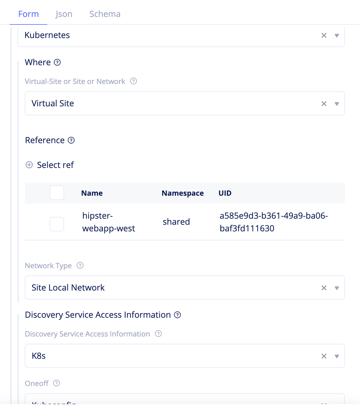
Figure: Service Discovery Configuration
- Encrypt Kubeconfig file for your EKS cluster using the F5 Distributed Cloud Blindfold:
vesctl request secrets encrypt --policy-document <policy-doc> --public-key <public-key> hipster-app-kubeconfig > hipster-app-bf-secret- Click
Kubeconfigand enter the configuration as per the following guidelines:- Select
Blindfoldfor theSecret infofield. - Enter the encrypted secret in the
Locationfield. - Select
EncodingNoneforSecret Encodingfield.
- Select
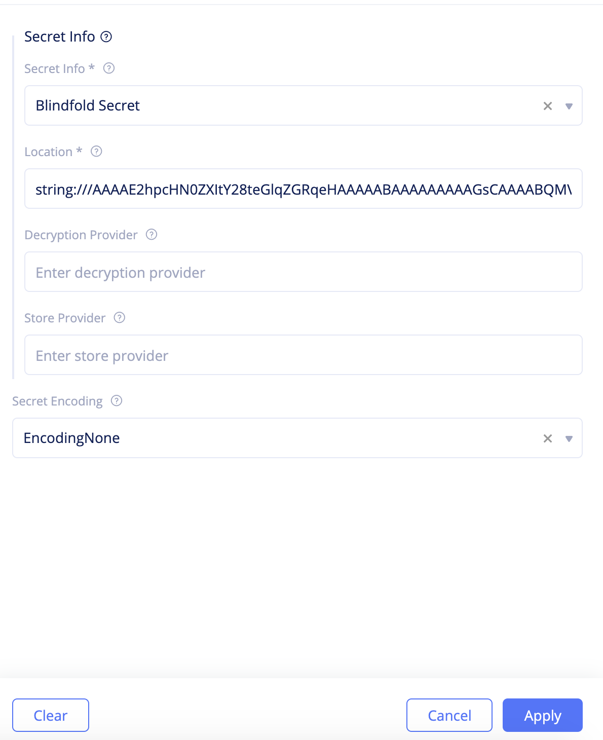
Figure: Service Discovery Secret Configuration
- Select
ApplyandAdd discoveryto create discovery object.
Step 3.3: Change to the app namespace and create endpoint.
-
Select
Manage>Endpoints. -
Click
Add endpointand enter the configuration as per the following guidelines:- Enter a name in the
Namefield. - Enter
Sitefor theWherefield and selecthipster-webapp-westfor theSelect reffield. - Select
Site Local Networkfor the network type. - Select
Service Selector InfoforEndpoint Specifierfield. - Select
Kubernetesfor theDiscoveryfield andService Namefor theServicefield. - Enter
frontend.hipsteras the service name. Herehipsteris the K8s namespace name. - Select
TCPas the protocol. - Enter 80 for the
Portfield. - Click
Add endpointto create endpoint.
- Enter a name in the
Step 3.4: Create health check.
-
Select
Manage>Healthcheck. -
Click
Add healthcheckand enter the configuration as per the following guidelines:- Enter a name in the
Namefield. - Select
HTTP HealthchecktheHealth checkfield. - Enter
/for path - Enter
5forTimeoutandIntervalfields. This sets timeout and interval as 5 seconds for health check. - Enter
3and1for Unhealthy Threshold and Healthy Threshold fields. - Click
Add healthchcek.
- Enter a name in the
Step 3.5: Create cluster.
-
Select
Manage>Clusters. -
Click
Add clusterand enter the configuration as per the following guidelines:- Enter a name in the
Namefield. - Select the endpoint created for the
Select endpointfield. - Select the healthcheck object created for the
Select healthcheckfield. - Select
Round Robinfor theLoadBalancer Algorithmfield. - Click
Add cluster.
- Enter a name in the
Step 3.6: Add route towards the created cluster.
-
Select
Manage>Routes. Enter a name and clickAdd route. -
Enter the configuration as per the following guidelines:
- Click
Add match. SelectANYfor theHTTP Methodfield andRegexfor thePath Matchfield. Enter(.*?)for theRegexfield and clickAdd match. - Select
Destination Listfor theRoute actionfield and clickAdd destination. ClickSelect clusterand select the cluster object created. ClickSelect clusterandAdd destinationto add the cluster. - Click
Add routeto create the route.
- Click
Step 3.7: Add advertise policy.
- Select
Manage>Advertise Policies. - Click
Add advertise policyand selectSitefor theWherefield. - Click
Select refand select the Site created in the Step 1: Provision section. - Select
TCPas the protocol and443as the port. - Click
Add advertise policyto complete creating the advertise policy.
Step 3.8: Encrypt the private key of the certificate using the Blindfold.
Use the public key and policy document obtained. This example shows the sample of generating a secret for your application domain. Store the output to a file.
vesctl request secrets encrypt --policy-document secure-kgw-demo-policy-doc --public-key hipster-co-public-key tls.key > tls.key.secretNote: The
tls.keyis the private key of the certificate you generated.
Step 3.9: Add a virtual host.
-
Select
Manage>Virtual Hosts. -
Click
Add virtual hostand set the configuration as per the following guidelines:- Enter name, application domain, and your proxy type. This sample uses
HTTPS_PROXYas the proxy type andhello-web-4.helloclouds.appas the domain. - Select previously defined route.
- Select previously created advertise policy.
- Click
TLS Parametersand clickAdd TLS certificatein the TLS configuration form. - Generate Base64 string of your certificate and enter it in the
string:///format in theCertificate URLfield. You can use theecho <certficiate> |base64command. - Click
Private keyand selectSecret infoasBlindfold secretand enter the secret in theLocationfield. SelectSecret EncodingasEncodingNone. ClickApplyandAdd virtual host.
- Enter name, application domain, and your proxy type. This sample uses
Note: Use the secret created in previous step.
Step 4: Secure
Securing the ingress and egress traffic requires you to set the network policies, service policies, WAF, and network firewall.
This example sets policies that allow egress traffic to github.com, block traffic to origin IP 8.8.8.8/32, and block egress traffic to some identified malicious domains. It also enables the WAF to block malicious ingress attacks, such as SQL injection traffic.
Step 4.1: Create network policy.
-
Change to the
systemnamespace and selectSecurity>Firewall>Network Policies. ClickAdd network policy. -
Set a name for the policy and select
Endpoints Reachable via all Outside Interfacesin theSelect Endpointfield ofAttachmentsection. This makes the policy apply to all endpoints.
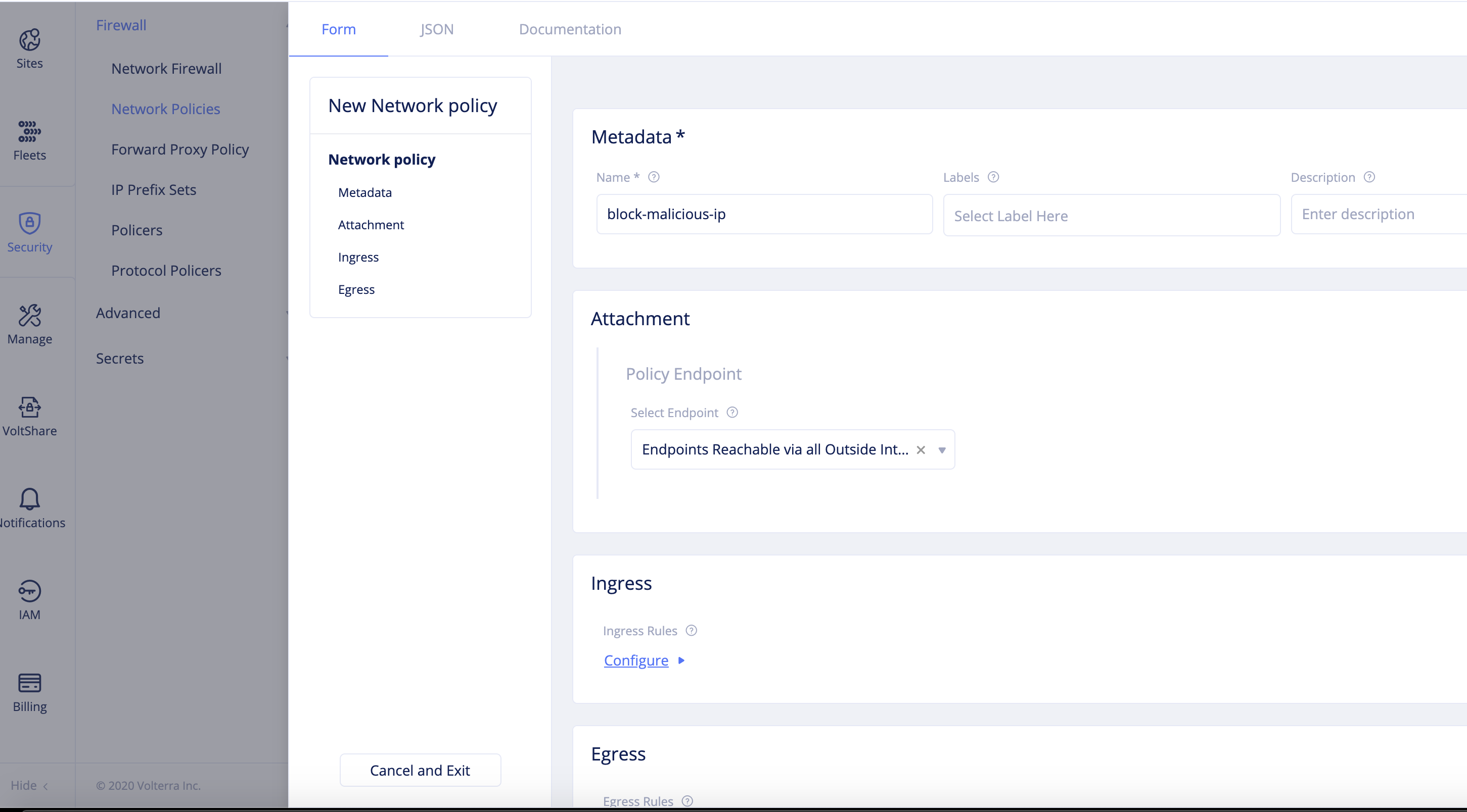
Figure: Network Policy Endpoint Configuration
-
Click
Configurein theEgresssection and configure egress rules as per the following guidelines:- Select
Denyfor theActionfield. - Select
IPv4 Prefix Listfor theSelect Other Endpointfield. - Set 8.8.8.8/32 for the
IPv4 Prefix Listfield. - Enter a name for the
Rule Namefield and clickApply.
- Select
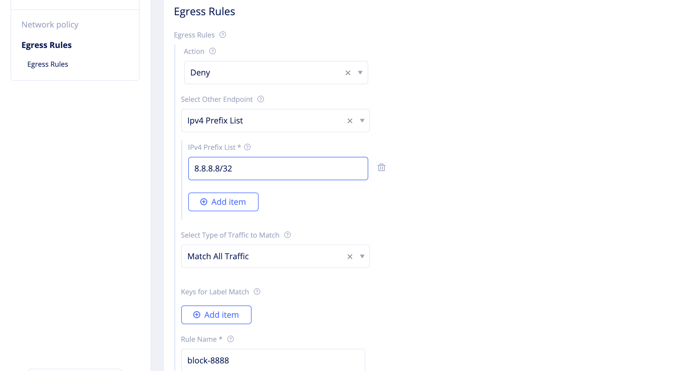
Figure: Network Policy Egress Rule
- Click
Continueto create the network policy.
Step 4.2: Create forward proxy policies.
Navigate to Security > Firewall > Forward Proxy Policy.
Step 4.2.1: Create a forward proxy policy to allow access to GitHub.
-
Click
Add forward proxy policyand enter the following configuration:- Set a name for the policy.
- Select
All Proxies on Sitefor theSelect Forward Proxyfield in theProxysection. - Select
Allowed Connectionsin theSelect Policy Rulessection and clickConfigureunder theTLS Domainsfield.
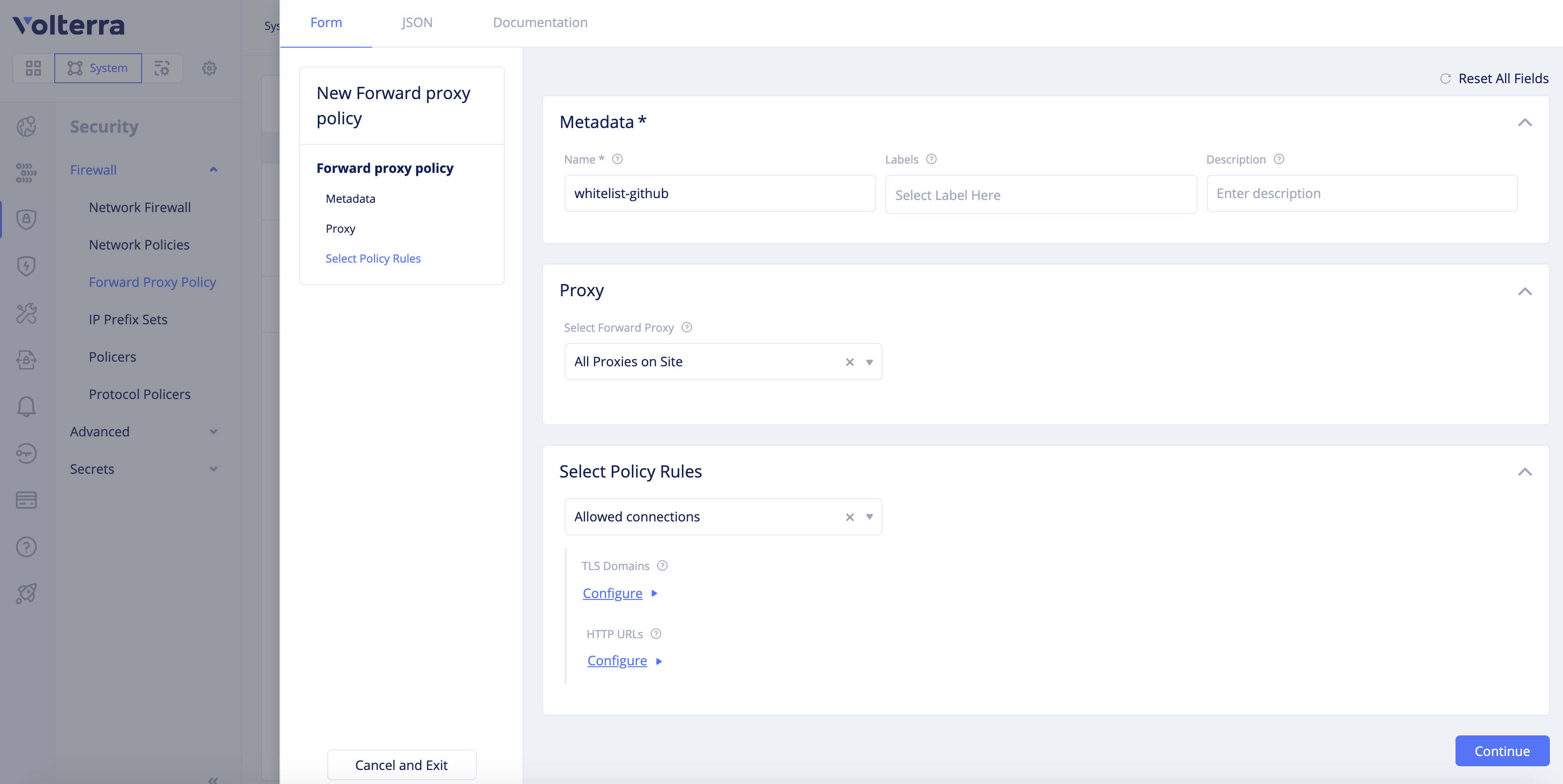
Figure: Forward Proxy Policy Rule Configuration
- Click
Add itemin theTLS Domainsscreen and entergithub.comin theExact Valuefield. You can changeEnter Domainfield to exact value or suffix value or regex values. However, the default is exact value.
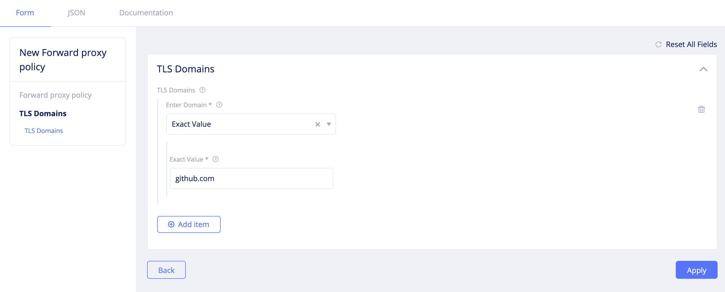
Figure: Forward Proxy Policy TLS Domain Configuration
- Click
Applyto add the TLS domain to the forward proxy policy configuration. - Click
Continueto complete creating the forward proxy.
Step 4.2.2: Create another forward proxy policy to block access to malicious sites of your choice.
- Set a name for the policy.
- Select
All Proxies on Sitefor theSelect Forward Proxyfield in theProxysection. - Select
Denied Connectionsin theSelect Policy Rulessection. - Click
Configurefor theTLS Domainsfield, clickAdd itemin the TLS domains screen, and select a value for theEnter Domainfield. - Enter a domain as per your domain type selection and click
Apply. This example setting suffix value.
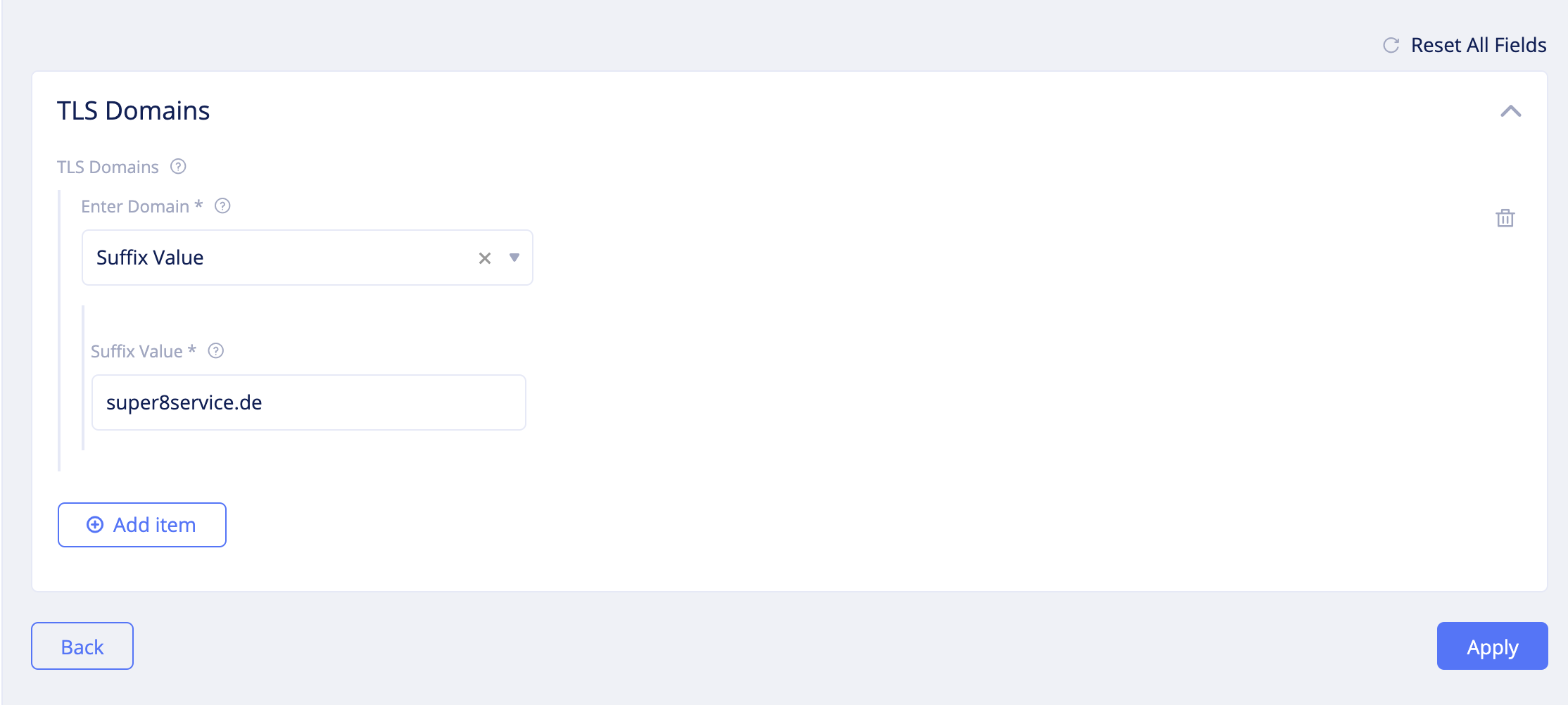
Figure: Forward Proxy Policy TLS Deny Configuration
- Similarly, click
Configurefor theHTTP URLsfield and add URLs of the Sites to which access is to be blocked and clickApply. This example shows sample Sites that are blocked.
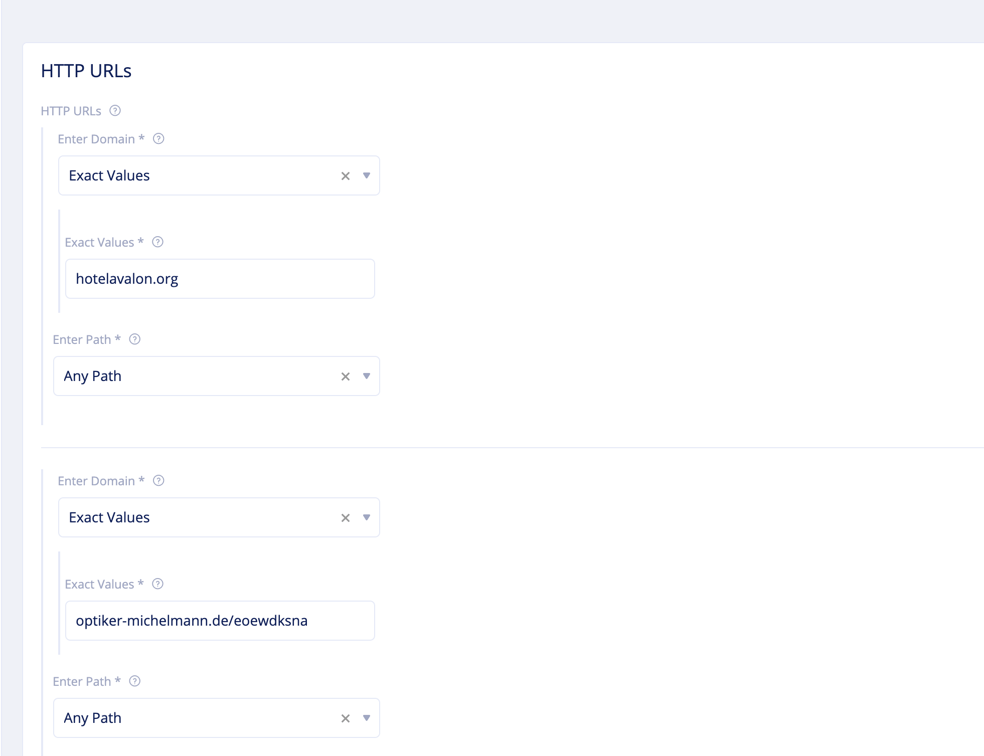
Figure: Forward Proxy Policy HTTP Deny Configuration
- Click
Continueto complete creating the forward proxy policy.
Step 4.3: Create network firewall.
-
Select
Security>Firewall>Network Firewall. ClickAdd network firewalland set the following configuration:- Set a name for the firewall.
- Select
Active Forward Proxy Policiesfor theSelect Forward Policy Configurationfield in theForward Proxy Policysection. - Select the deny policy created in the previous step for the
Forward Proxy Policiesfield. - Click
Add itemand add the GitHub allow policy. - Select
Active Network Policiesfor theSelect Network Policy Configurationfield in theNetwork Policysection. - Select the deny policy for IP address range 8.8.8.8/32 created in the previous step for the
Network Policiesfield.
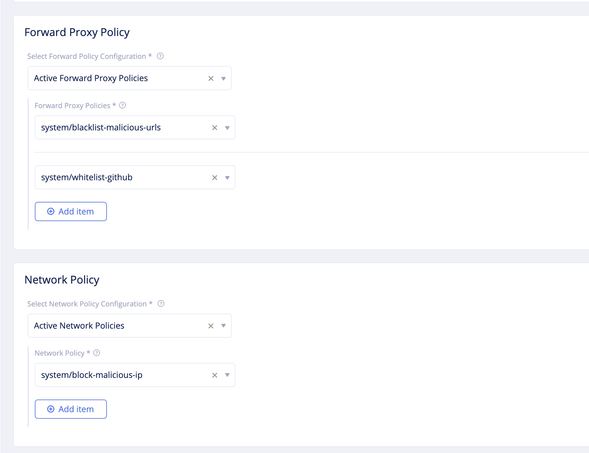
Figure: Network Firewall Configuration
- Click
Continueto complete creating network firewall.
Step 4.4: Apply the network firewall to the fleet.
- Select
Manage>Site Management>Fleetsand find your fleet from the displayed list. - Click
...>Editto open the fleet edit form. - Click
Select network firewalland select the firewall created in the previous step. - Click
Save changesto apply the network firewall to the fleet of Sites.
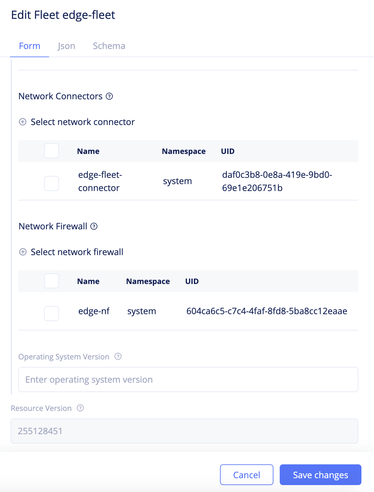
Figure: Network Firewall Addition to Fleet
Note: After adding the network firewall to the fleet, any updates to the network policy or forward proxy policy are applied to all Sites that are part of that fleet.
Step 4.4: Create a WAF and apply it to virtual host.
-
Change to your application namespace and create WAF.
- Navigate to
Security>App Firewall>App Firewall. - Click
Add firewall. - Enter a name and select
BLOCKfor theModefield. - Click
Add firewallto complete creating the WAF.
- Navigate to
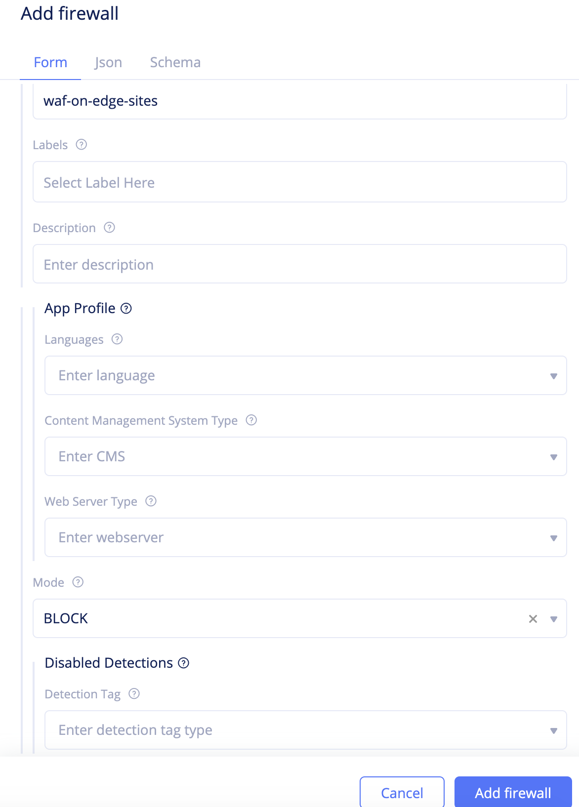
Figure: WAF Creation
-
Navigate to your virtual host and apply the WAF.
- Navigate to
Manage>Virtual Hosts. Find your virtual host from the displayed list and click...>Editto open the virtual host edit form. - Scroll down and click
WAF Configto open the WAF configuration form. - Select
WAFfor theWAF Configfield. ClickSelect WAF, select the created WAF, and clickApply. - Click
Save changesto apply WAF to virtual host configuration.
- Navigate to
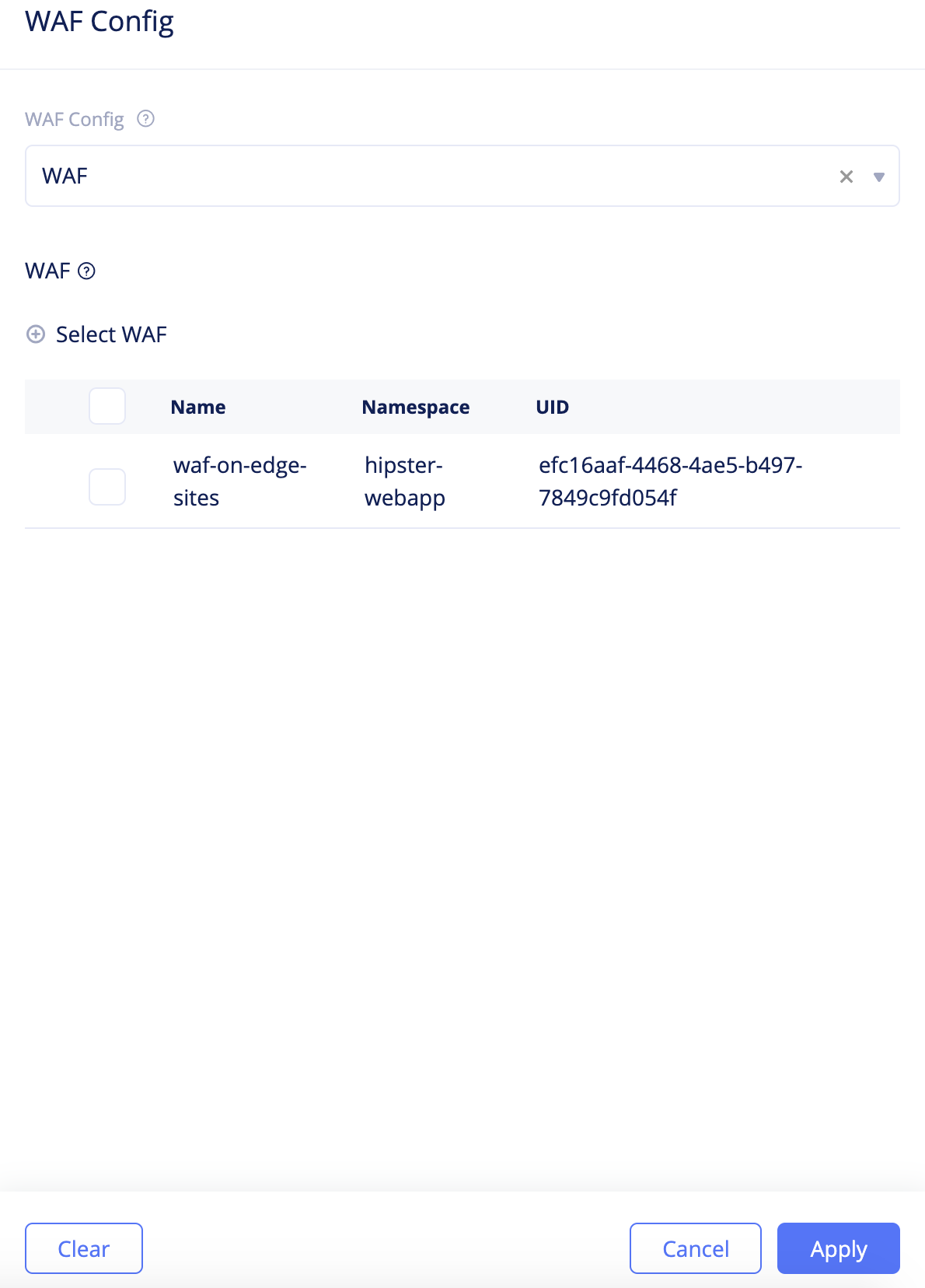
Figure: Apply WAF to Virtual Host
Verify Applied Security Policies
The applied security policies block egress traffic toward 8.8.8.8/32 and also toward malicious URLs as per the configuration. Also, traffic towards GitHub is allowed. You can also inspect the virtual host and site monitoring for requests and alerts.
Step 1: Verify requests.
- Use
curlcommand load github.com and GitHub should be allowed. - Use
curlcommand to load the URLs you configured to block in the forward proxy deny policy. The requests should be rejected. - Enter
ping 8.8.8.8/32from the command line and this should be unsuccessful.
Step 2: Verify the requests on the site dashboard.
- Navigate to
Sites>Site Listand click on your site to open its dashboard. - Click on the
Requeststab and check the sample requests. Your requests to the blocked sites are displayed along with the HTTP return code.
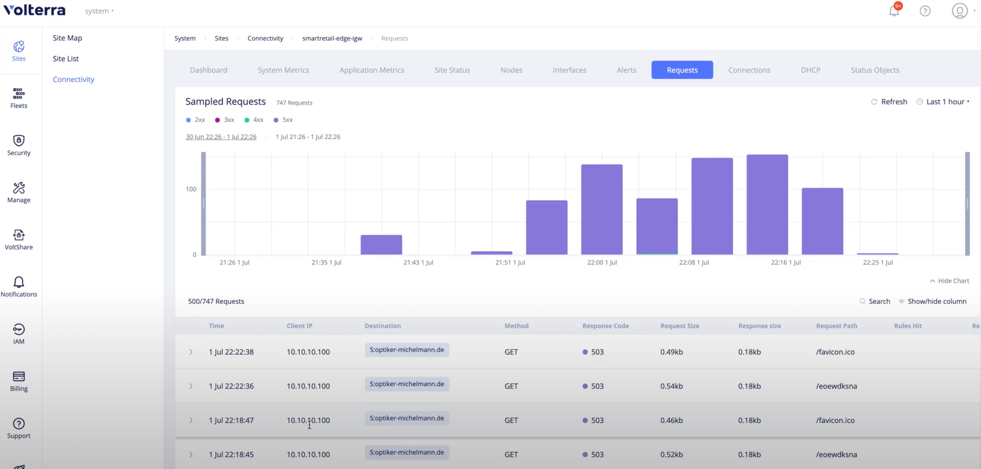
Figure: Sampled Site Requests
Step 3: Verify alerts related to your site.
- Change to
systemnamespace and navigate toNotifications>Alerts. By default, active alerts are displayed for all sites. Filter the alerts for your site by entering your site name in theSearchfield. - Switch to all alerts using the
Alloption. All alerts for your site are displayed.
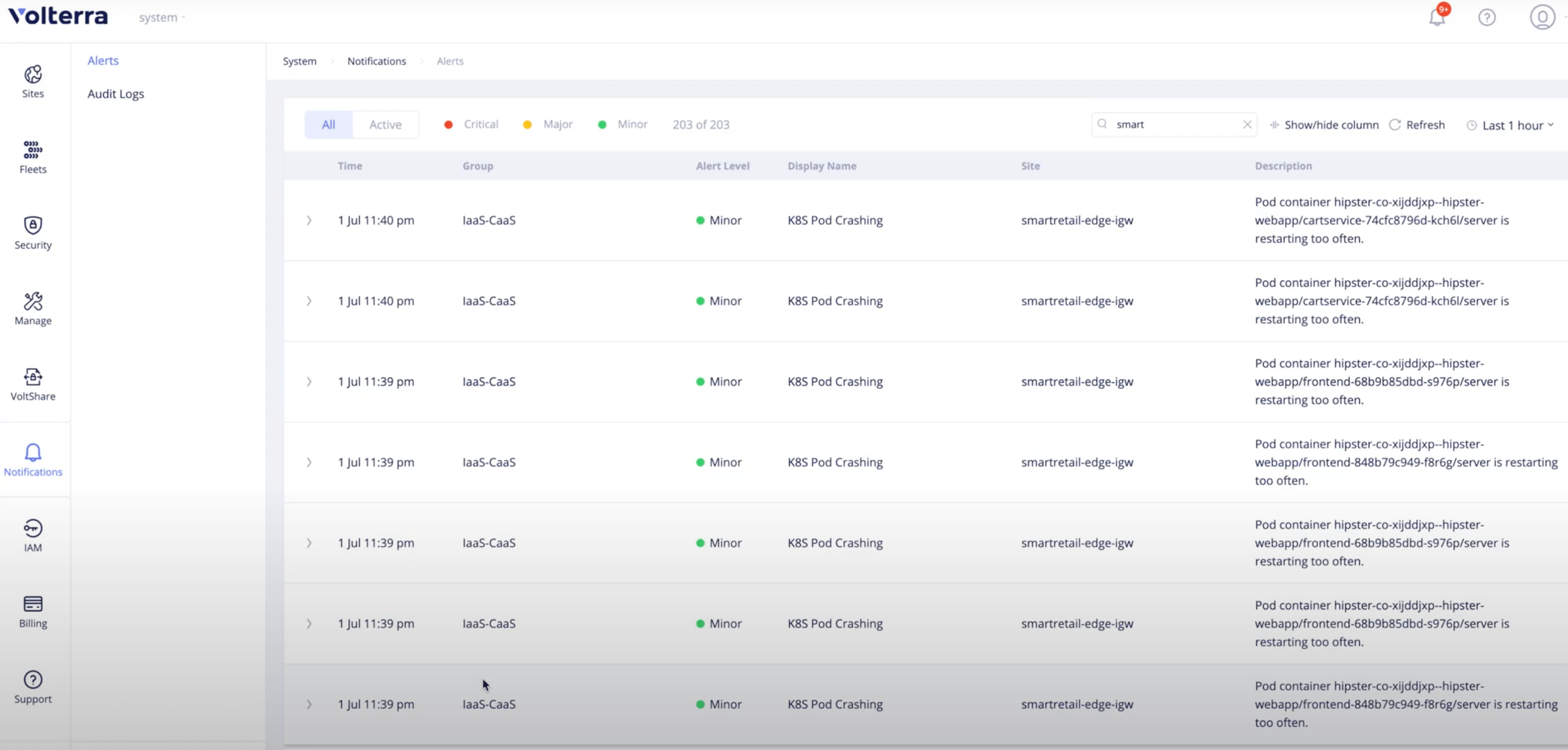
Figure: Site Alerts
Note: You can also post your alerts to a 3rd party monitoring system or communication platform, such as OpsGenie or Slack. For more information, see the Alerting guides.
Concepts
- System Overview
- Core Concepts
- Networking
- F5 Distributed Cloud - Customer Edge
- Endpoint
- Cluster
- Route
- Advertise policy
- Virtual Host