Deploy Site in GCP (ClickOps)
Objective
Important: This is a legacy workflow for deploying Customer Edge (CE) sites and is not recommended to use. A new workflow for deploying Customer Edge (CE) sites has been introduced and is now Generally Available (GA). F5 recommends you use the new Secure Mesh Site (v2) workflow for all your Customer Edge deployments. You can find this workflow here.
This guide provides instructions on how to create a customer edge (CE) site using the Google Cloud Provider (GCP) Console and deploy to a GCP VPC. For more information on sites, see F5® Distributed Cloud Site.
Site Types and Scenarios
The scenarios below in the table have been tested successfully. The Network Address Translation Gateway (NAT GW) device in Table 1 references the GCP NAT Gateway. However, technically this should also work with third-party firewalls.
Note: In the
Number of Nodescolumn,1/3indicates 1 or 3 nodes. An App Stack site can be configured with up to 128 worker nodes total.
| Provider | Site Type | Number of Control Nodes | Gateway Type | Interfaces | Scenario |
|---|---|---|---|---|---|
| GCP | Mesh | 1/3 | Ingress | 1 | Mesh Single-NIC |
| GCP | Mesh | 1/3 | Ingress/Egress | 2 | Mesh Multi-NIC |
| GCP | App Stack | 1/3 | - | 1 | App Stack Combo |
Considerations for Sites Behind NAT Gateway
In a regular deployment, each CE node has an External IP address associated with the Site Local Outside (SLO) interface, and the SLO route table routes the outgoing traffic via the Internet Gateway using the External IP address as the NAT IP address. But for scenarios where there is a requirement to have the CE site deployed without a public IP address, you can place the CE site behind a NAT Gateway. This can be the GCP Cloud NAT or any third-party instance, like a firewall used as a NAT gateway.
If you are deploying a site in this scenario, there are a few differences to note:
-
There is no public IP association with the CE(s).
-
You must ensure the CE can get to the Internet through its SLO interface.
-
From the GCP side, ensure that the routing table from the SLO subnet has a default route 0.0.0.0/0 that points to the NAT Gateway.
-
The NAT Gateway is a zonal object. In other words, it belongs to one availability zone. Therefore, in the case of a three-node CE cluster, you might want to deploy additional NAT Gateways for high availability.
Prerequisites
The following prerequisites apply:
-
A Distributed Cloud Services Account. If you do not have an account, see Getting Started with Console.
-
An account with GCP. See Required Access Policies for permissions needed to deploy site. To create a cloud credentials object, see Cloud Credentials.
-
An official F5 Distributed Cloud Services GCP image.
-
Resources required per node: Minimum 4 vCPUs, 14 GB RAM, and 80 GB disk storage. However, to deploy an F5® Distributed Cloud App Stack Site, 100 GB is the recommended minimum amount of storage. For a full listing of the resources required, see the Customer Edge Site Sizing Reference guide. All the nodes in a given CE Site should have the same resources regarding the compute, memory, and disk storage. When deploying in cloud environments, these nodes should use the same instance flavor.
-
Allow traffic from and to the Distributed Cloud public IP addresses to your network and allowlist related domain names. See F5 Customer Edge IP Address and Domain Reference for Firewall or Proxy Settings guide for the list of IP addresses and domain names.
-
F5 assumes that the resource group exists with a virtual network, including a minimum of two subnets: one for the Site Local Outside (SLO) and one for the Site Local Inside (SLI). The CE generally references the SLO interface as
eth0and the SLI interface aseth1. -
For a single-NIC deployment (ingress gateway/Mesh or App Stack), only a single subnet (SLO) is required.
-
Internet Control Message Protocol (ICMP) needs to be opened between the CE nodes on the Site Local Outside (SLO) interfaces. This is needed to ensure intra-cluster communication checks.
Important: After you deploy the CE Site, the IP address for the SLO interface cannot be changed. Also, the MAC address cannot be changed.
Procedure
This procedure provides instructions for creating a Secure Mesh Site with two interfaces (ingress/egress) on a GCP VPC using GCP Console. Most of the objects and configurations are the same for single-node and multi-node sites.
Create GCP VPC Networks
Create two VPC networks to attach to the Site Local Outside (SLO) and Site Local Inside (SLI), respectively. Each of the VPC networks must have one subnet.
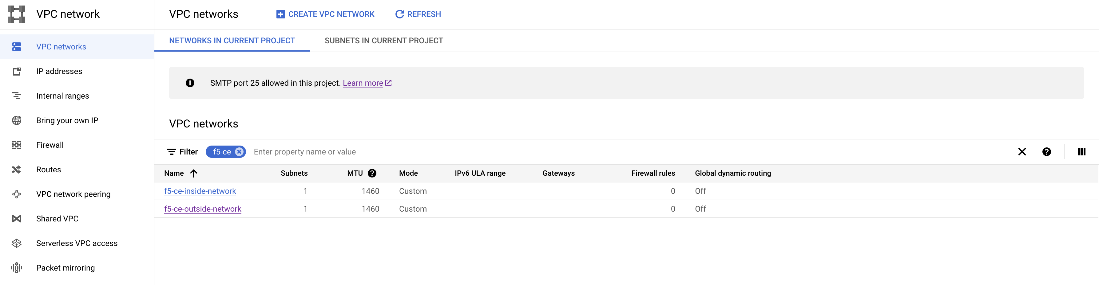
- In GCP Console, navigate to your VPC network.
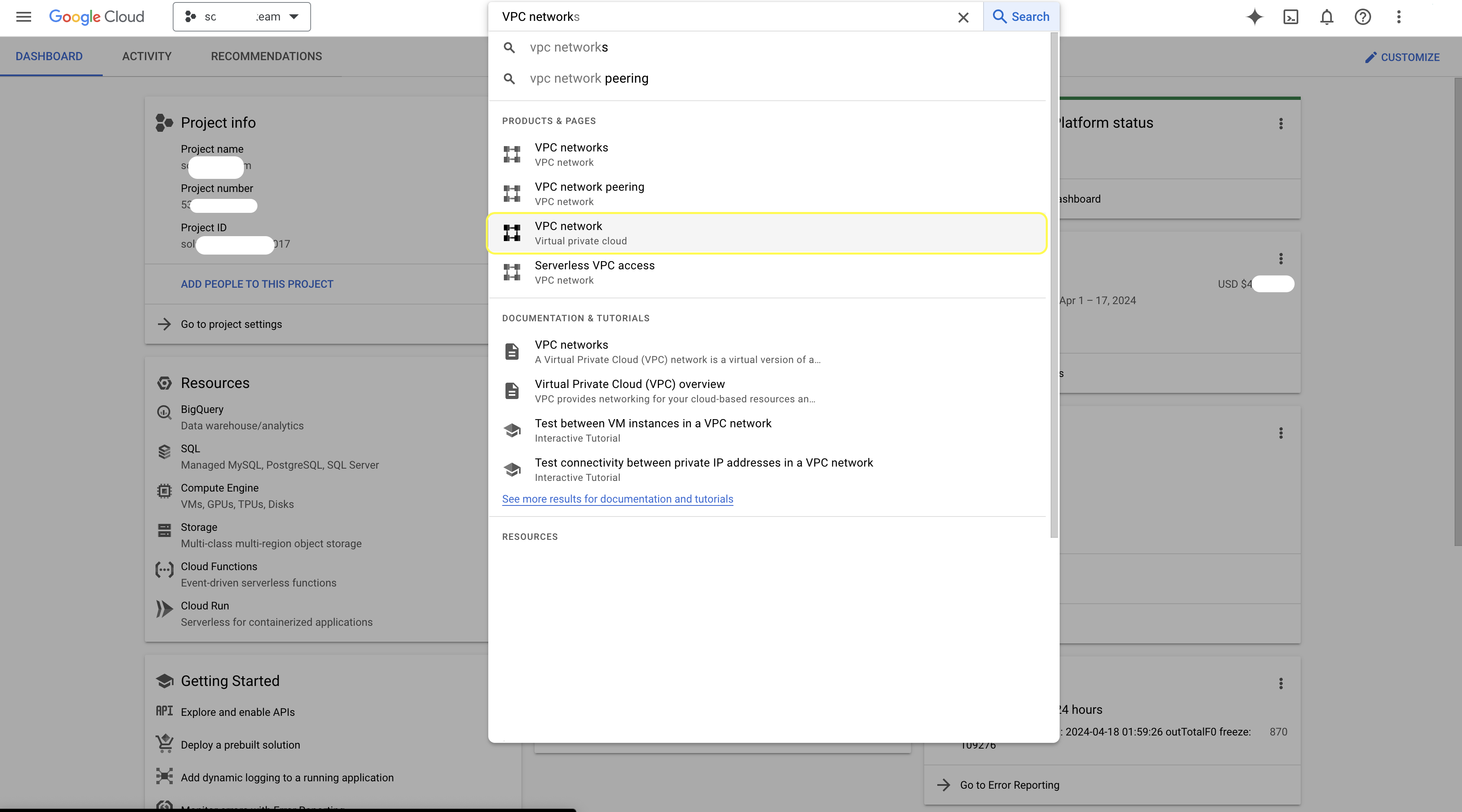
Figure
- Click
CREATE VPC NETWORK.
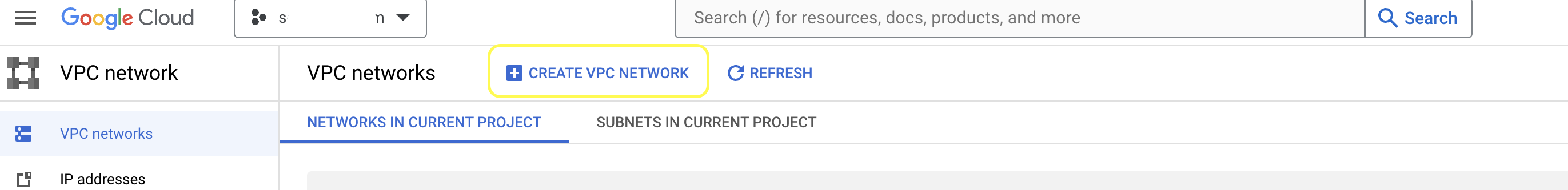
Figure
- In the
Namefield, enter a name for the outside network subnet, and then clickADD SUBNET.
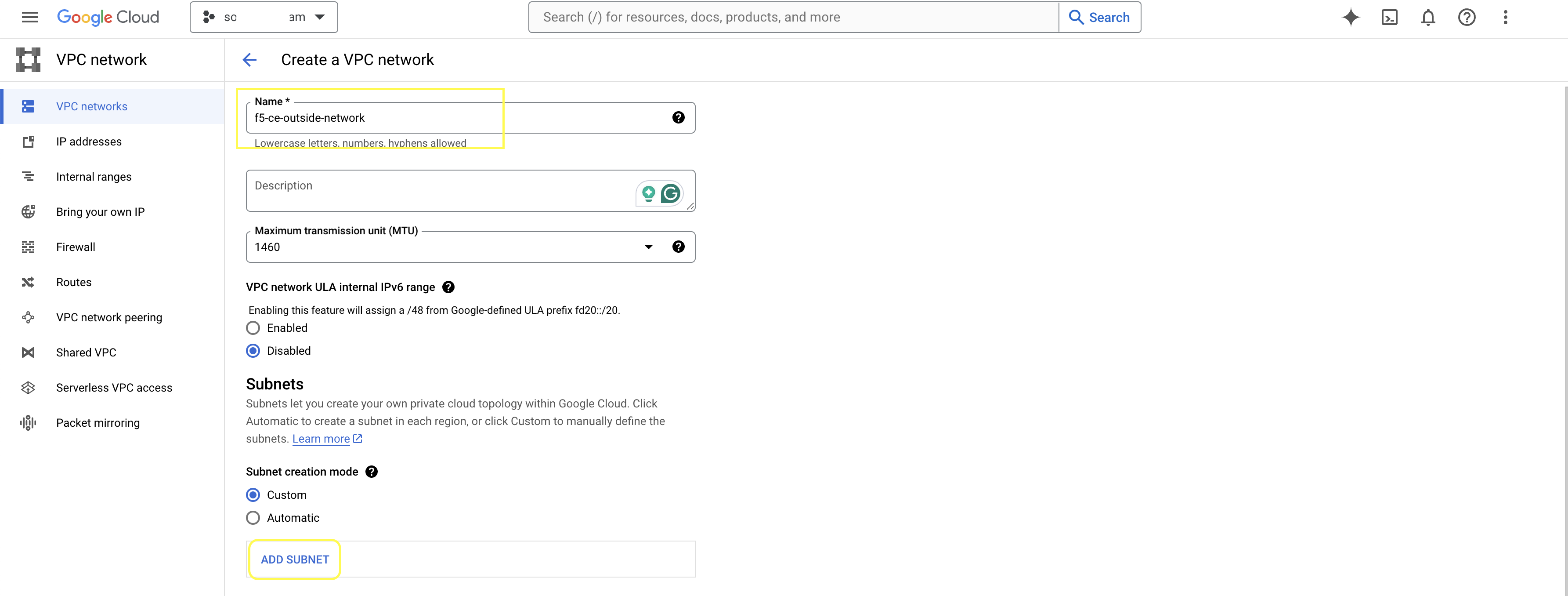
Figure
- Configure the outside subnet details, and then click
DONE.
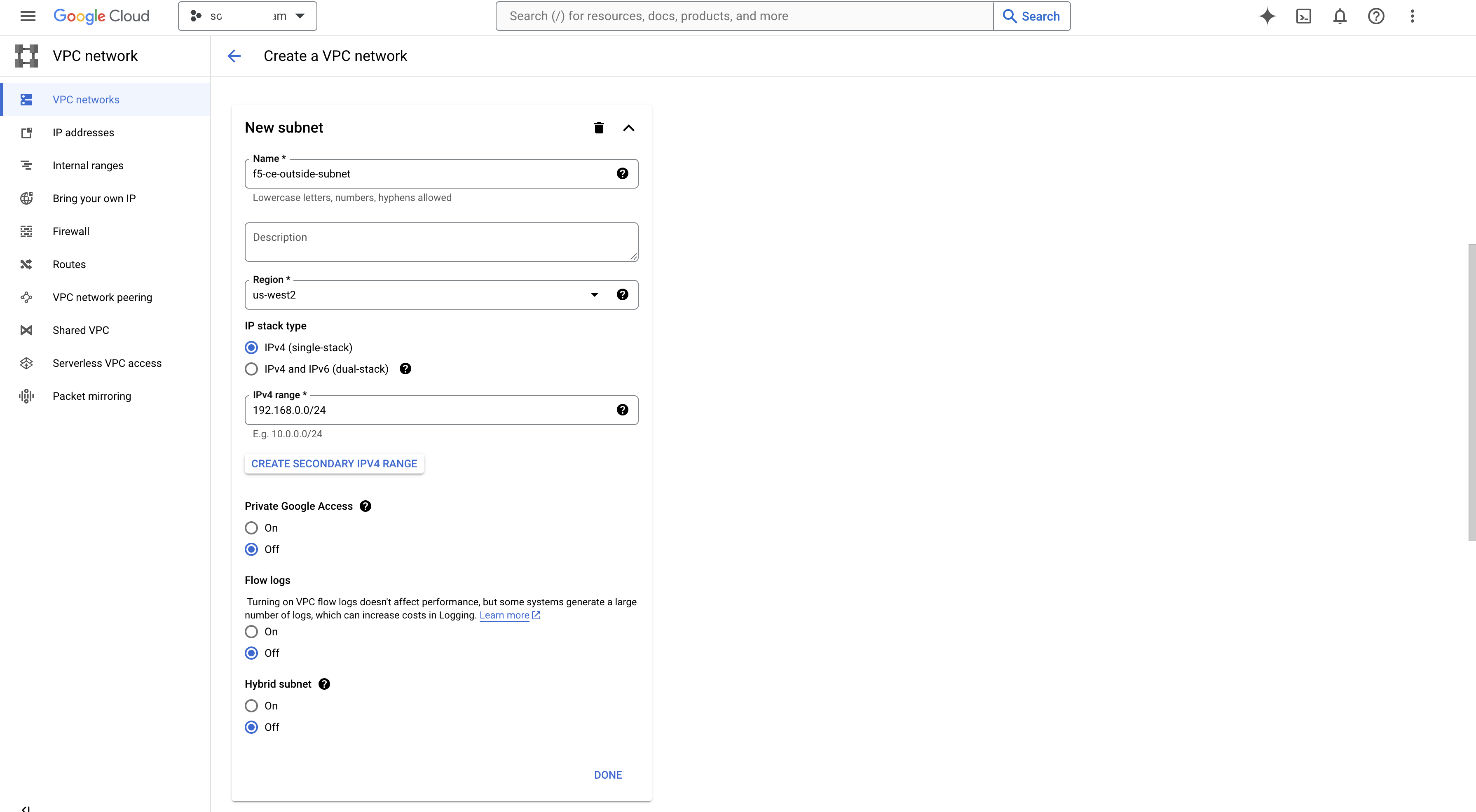
Figure
- Keep other configuration parameters as default and click
CREATEto finish.
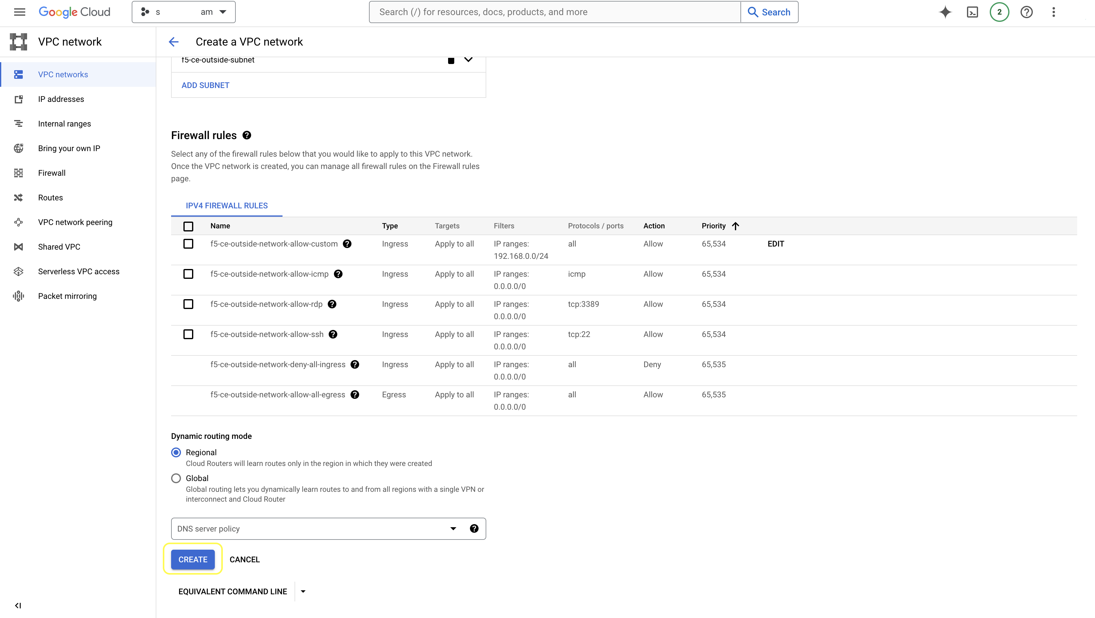
Figure
- Perform the same procedure for the inside (SLI) network.
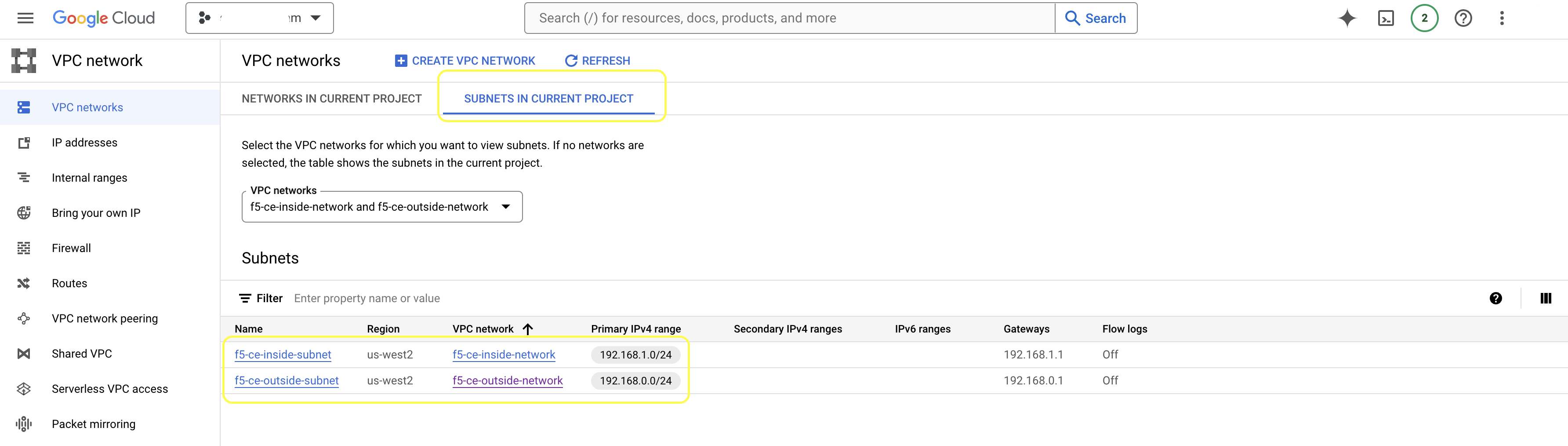
Figure
Create Firewall Rules
Create ingress and egress firewall rules for both inside and outside VPC networks (from the previous section).
Step 1: Configure ingress rules for SLI.
- For your VPC, locate and select the SLI network.
Figure
- Select the
FIREWALLStab, and then clickADD FIREWALL RULE.
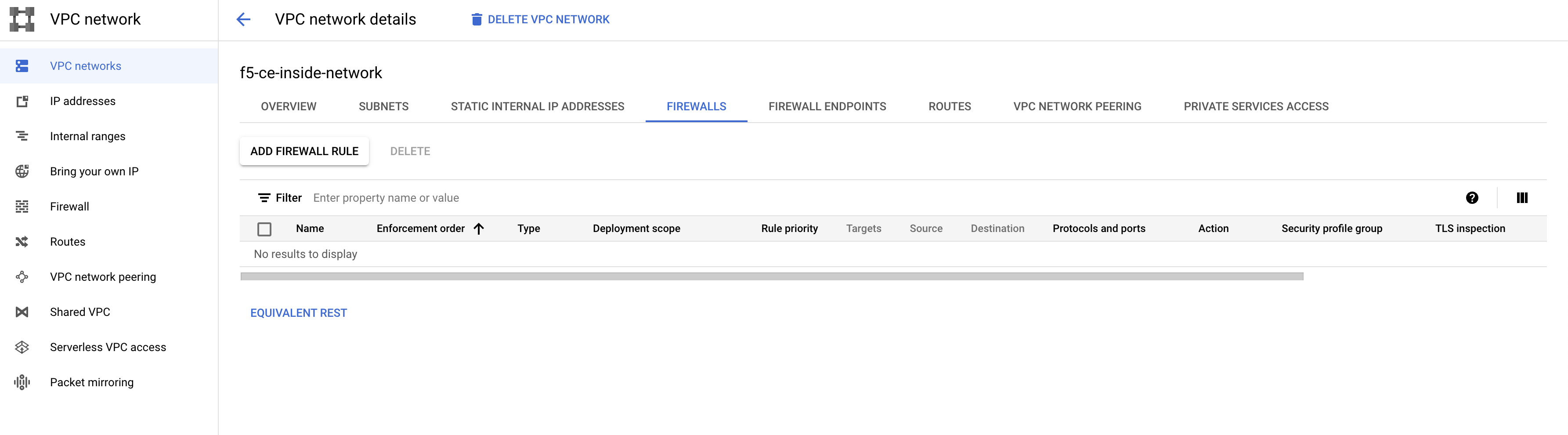
Figure
- Create
Ingressrule for the inside network that allows traffic from the0.0.0.0/0network to any target with tag:f5-ce(create any tag name, as it will be used to identify the VM instance).
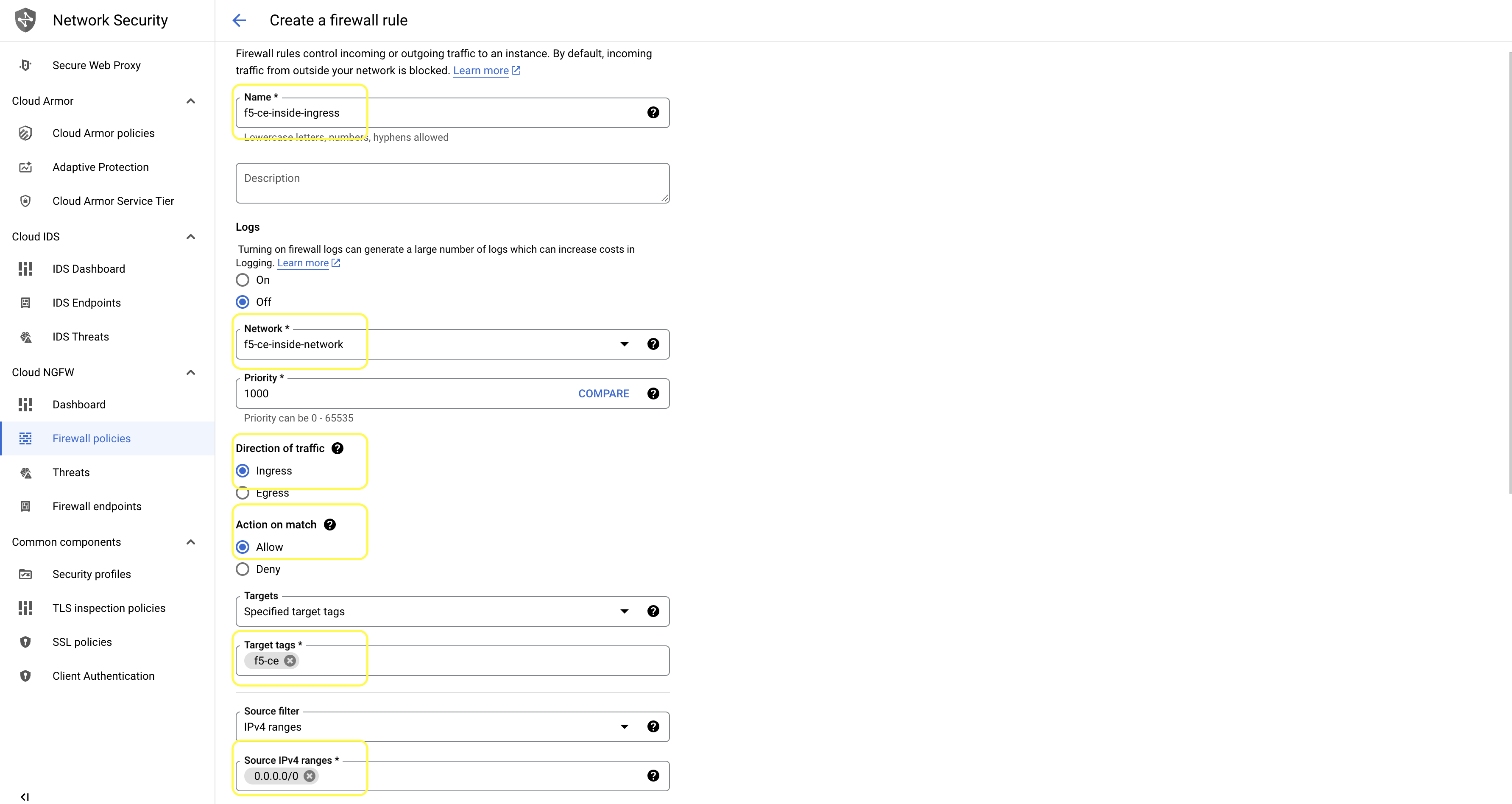
Figure
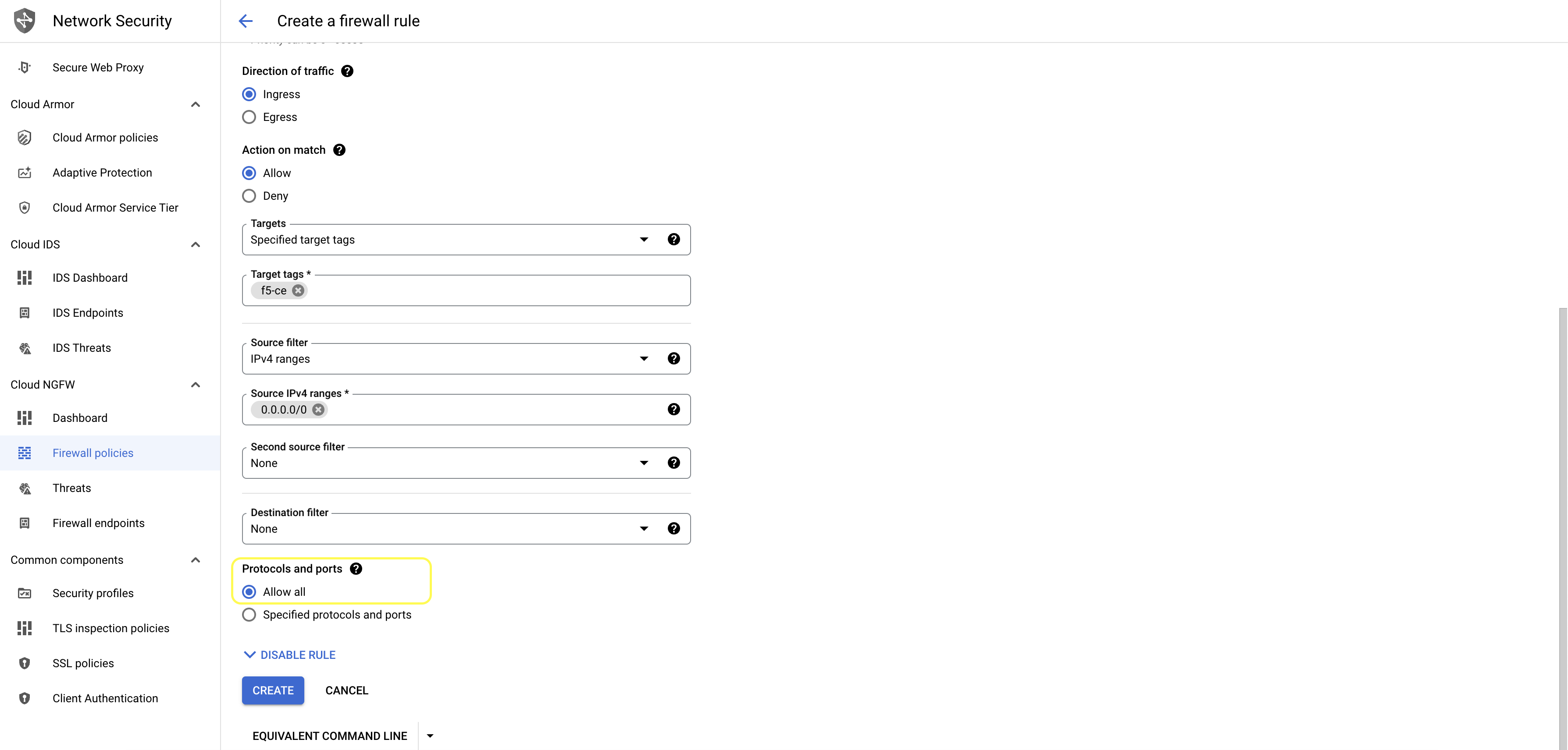
- Under
Protocols and port, selectAllow alland clickCREATE.
Figure
Step 2: Configure egress rules for SLI.
-
Select the
FIREWALLStab, and then clickADD FIREWALL RULE. -
Create
Egressrule for the inside network that allows traffic to the0.0.0.0/0network from target with tag:f5-ce.
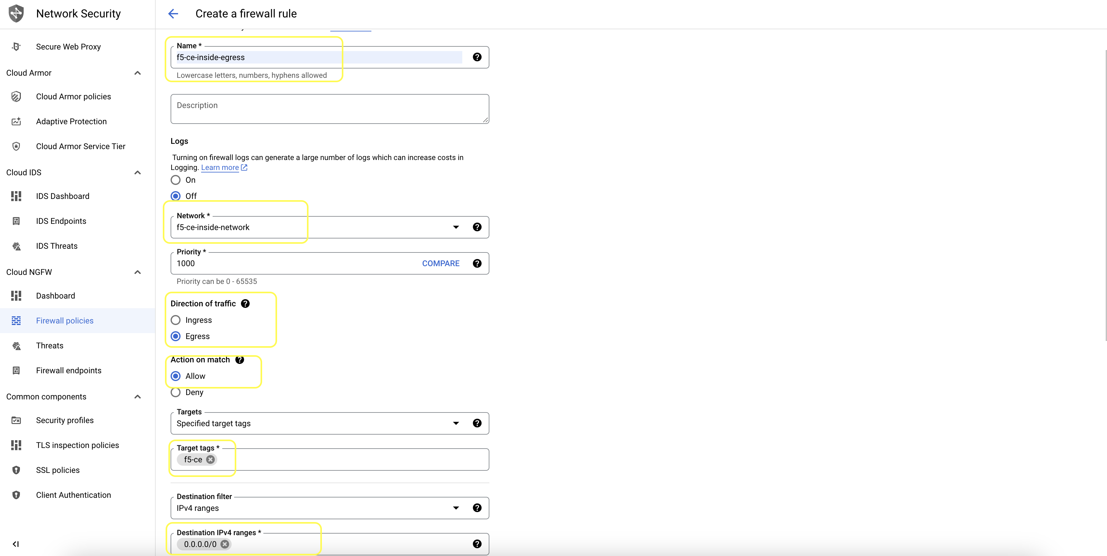
Figure
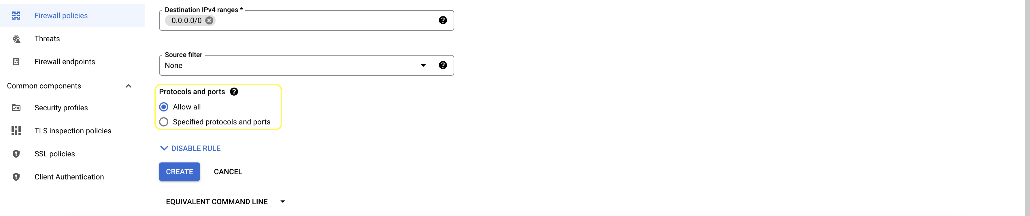
- Under
Protocols and port, selectAllow alland clickCREATE.
Figure
- Verify the rules.
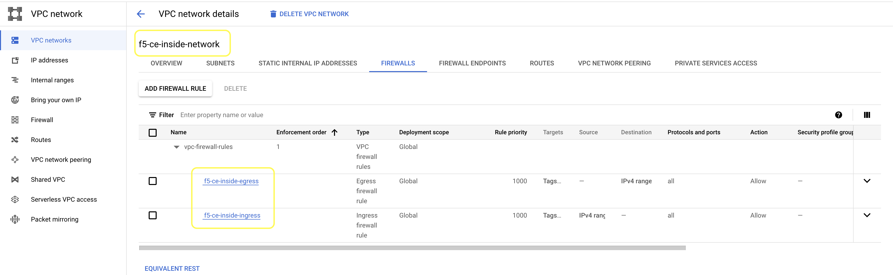
Figure
Step 3: Configure ingress/egress rules for SLO.
-
Select the outside network and repeat steps 1 and 2 above to create the same ingress and egress rules for SLO.
-
Verify the rules.
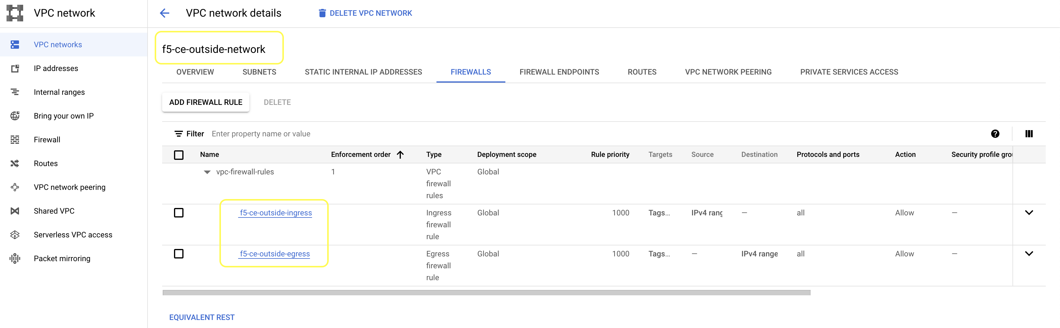
Figure
Import and Configure F5 CE Image
Import the official F5 CE image file into GCP, and then configure its parameters.
Step 1: Download official image.
| Image Type | Image | Cloud Storage File |
|---|---|---|
| Mesh Single-NIC | rhel9-20240216075746-single-voltmesh | ves-images/rhel9-20240216075746-single-voltmesh.tar.gz |
| Mesh Multi-NIC | rhel9-20240216075746-multi-voltmesh | ves-images/rhel9-20240216075746-multi-voltmesh.tar.gz |
| App Stack Combo | rhel9-20240216075746-voltstack-combo | ves-images/rhel9-20240216075746-voltstack-combo.tar.gz |
- Navigate to F5 CE GCP Images and download the image file locally.
Step 2: Upload and configure image.
- In GCP Console, navigate to
ImagesunderStoragesection inCompute Engine.
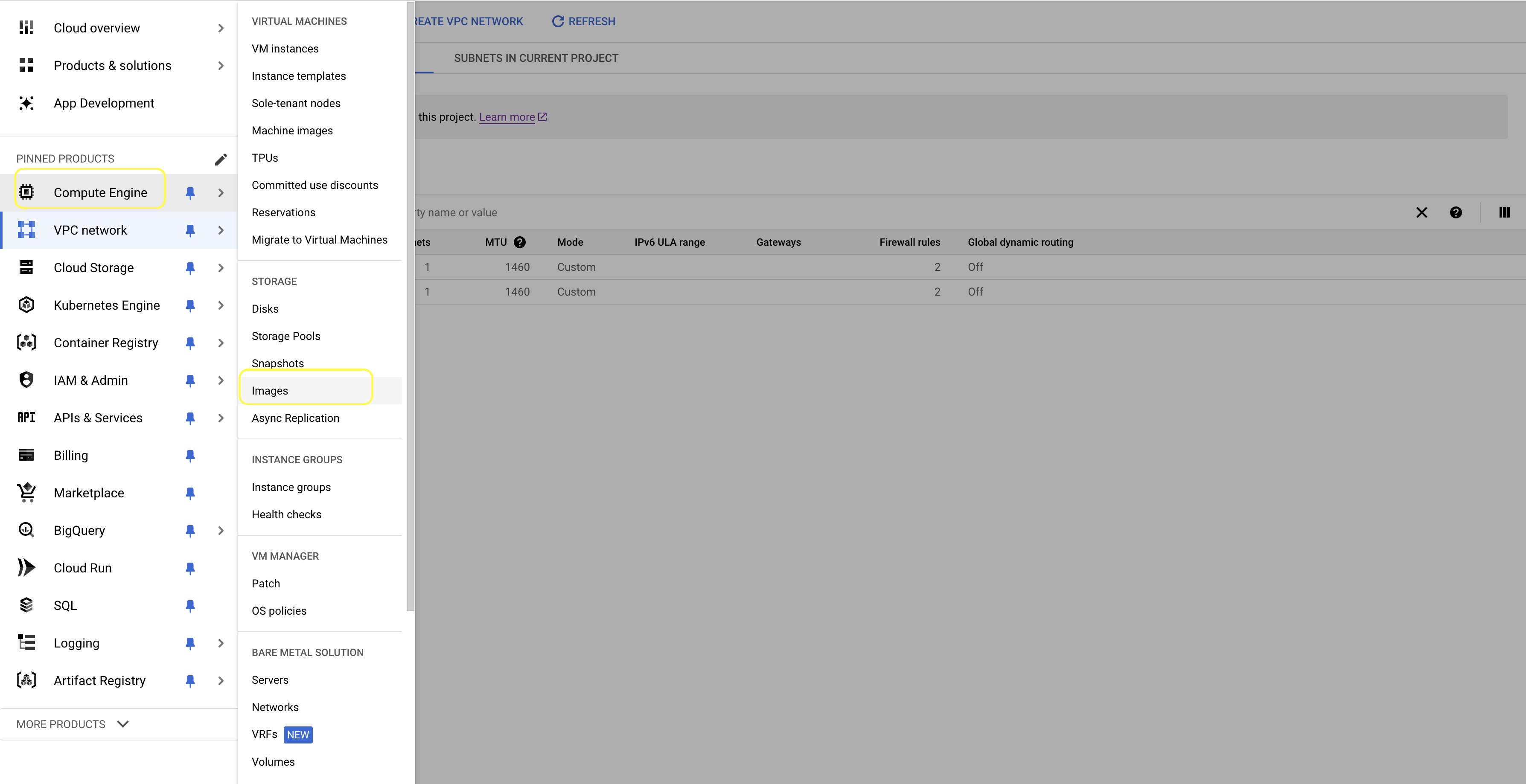
Figure
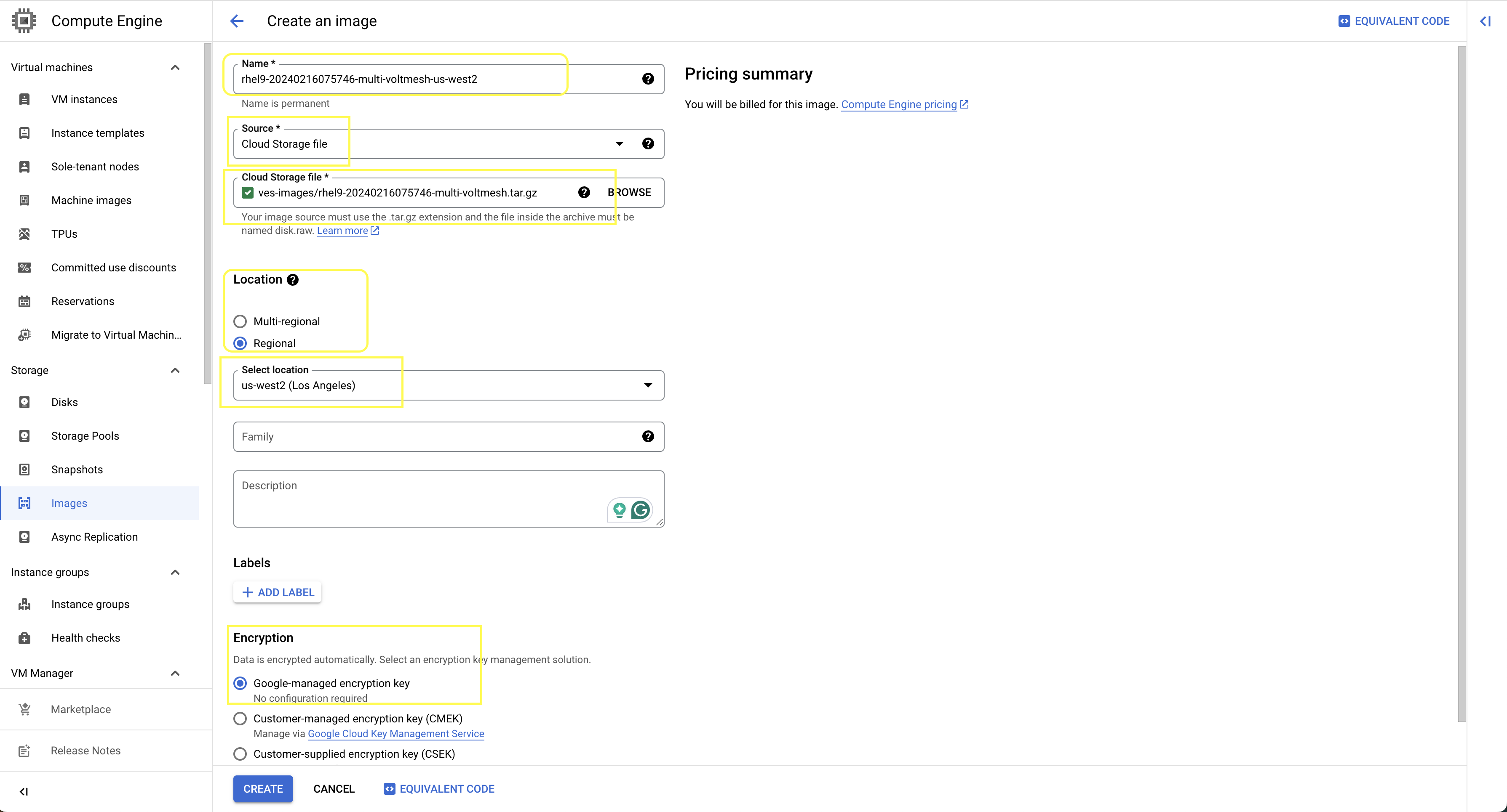
- Click
CREATE IMAGE.
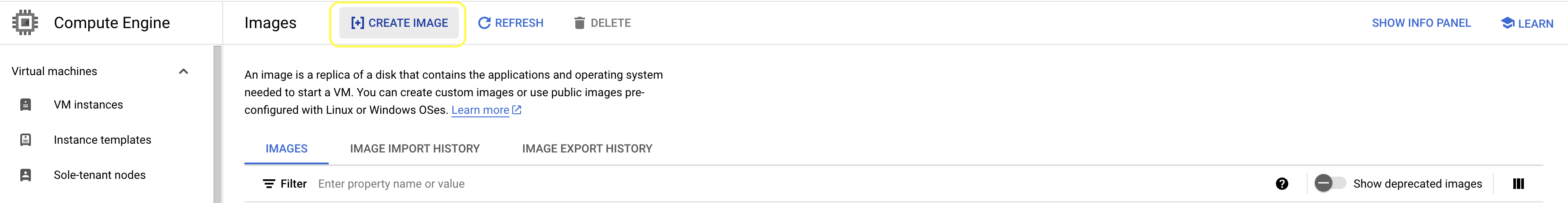
Figure
-
For the Mesh Multi-NIC image, use the following as an example:
-
Enter a
Name. This example usesrhel9-20240216075746-multi-voltmesh-us-west2. -
For
Source, selectCloud Storage file. -
Use the
Cloud Storage fileoption to browse for and select the image file. This example usesves-images/rhel9-20240216075746-multi-voltmesh.tar.gz. -
For
Location, select an option. This example usesRegional. -
For
Select location, select your desired location. This example usesus-west2. -
For the
Encryptionoption, selectGoogle-managed encryption key.
-
-
Click
CREATE.
Figure
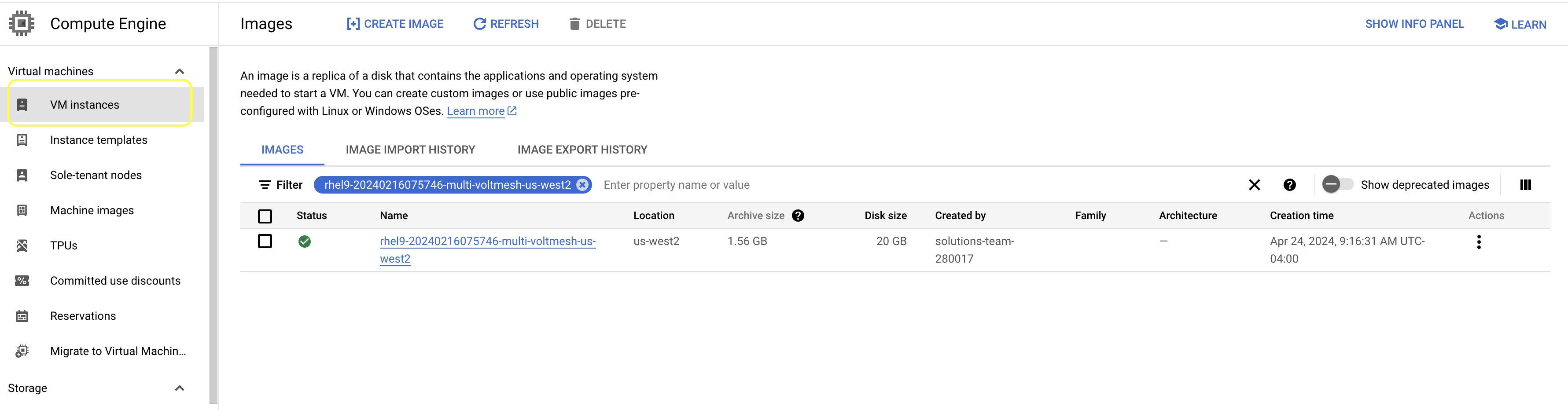
Step 3: Verify image uploaded successfully.
Verify image uploaded and status is a green checkmark.
Create Site Token
Create a site token or use an existing token. If you are configuring a multi-node site, use the same token for all nodes. To create the token, see the Create Site Token guide.
Configure User Data for Virtual Machine
Below is the cloud config user data example for the GCP VM instance that configures the VM.
#cloud-config
#Only values to be inserted are token and cluster name. Insert as is without parenthesis
write_files:
- path: /etc/hosts
  content: |
    # IPv4 and IPv6 localhost aliases
    127.0.0.1         localhost
    ::1               localhost
    127.0.1.1         vip
    169.254.169.254   metadata.google.internal
  permissions: 0644
  owner: root
- path: /etc/vpm/config.yaml
  permissions: 0644
  owner: root
  content: |
    Vpm:
      ClusterType: ce
      ClusterName: #### TO BE REPLACED BY THE F5XC SECURE MESH SITE NAME ####
      Token: #### TO BE REPLACED BY F5XC API TOKEN ####
      MauricePrivateEndpoint: https://register-tls.ves.volterra.io
      MauriceEndpoint: https://register.ves.volterra.io
      CertifiedHardwareEndpoint: https://vesio.blob.core.windows.net/releases/certified-hardware/gcp.yml
    Kubernetes:
      EtcdUseTLS: True
      Server: vip
      CloudProvider: disabled
-
Change the following mandatory fields:
-
ssh_authorized_keys: Enter your SSH public key. -
ClusterName: Enter the site name for the site object created on F5 Distributed Cloud Console. This can be an App Stack Site or Secure Mesh Site. -
Token: Enter the value for the site token created on F5 Distributed Cloud Console. This value is used to identify the tenant.
-
Deploy Multi-Node Site
Follow these steps to create a multi-node Secure Mesh Site.
Reserve External IP Addresses
Create three external IP addresses and give each a name. These IP addresses are used later for the virtual machine instances.
- In
VPC network, navigate toIP addresses. Then clickRESERVE EXTERNAL STATIC IP ADDRESS.

Figure: Reserve External IP Address
-
Enter a
Name. -
Under
Network Service Tier, select an option. -
Confirm
Regionand other parameters are configured correctly.
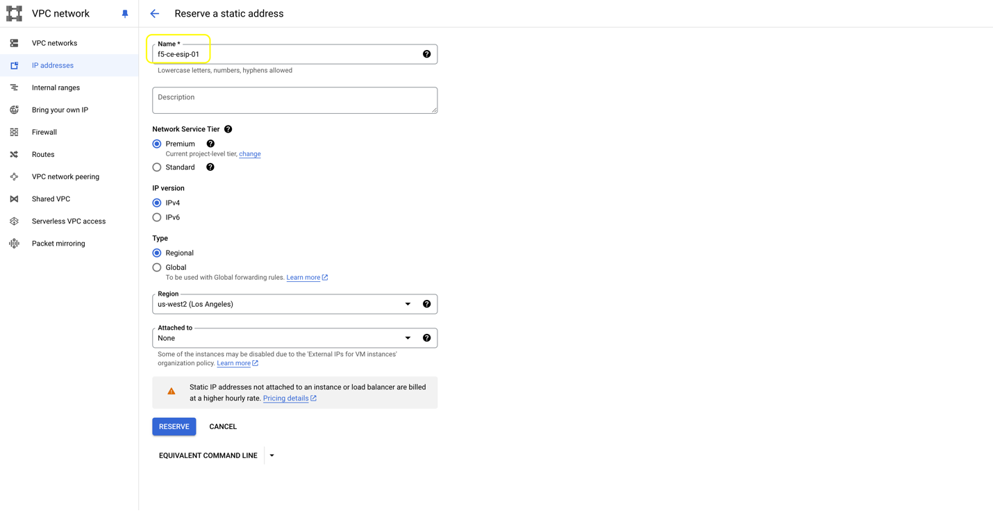
Figure: Reserve External IP Address
- Repeat the above steps to create two more External Static IP addresses. For example, create
f5-ce-esip-02andf5-ce-esip-03for node two and node three of your site.
Create the F5 Customer Edge Node Instances
Create the F5 CE VM instances in GCP.
- In
Compute Engine, underVirtual machines, clickVM instances.
Figure
- Click
CREATE INSTANCE.
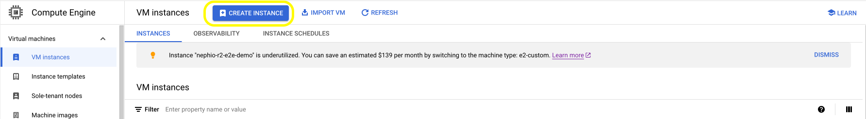
Figure
- Use the following table help with the example parameters:
| Parameter | Value | Notes |
|---|---|---|
| Name | f5-ce-node-01, f5-ce-node-02, f5-ce-node-03 | Names of nodes for CE site. |
| Region | us-west2 | Region from GCP. |
| Zone | us-west2-a, us-west2-b, us-west2-c | Zones from GCP. |
| Machine Configuration/Machine Type | n2-standard-8 | Recommended instance types: See Customer Edge Site Sizing Reference. |
| Certified Hardware Name | single NIC: gcp-byol-voltmesh / multi-NIC: gcp-byol-multi-nic-voltmesh | This is the certified hardware name. |
| VM Provisioning Model | Standard | Keep the default value. |
| Confidential VM Service | Disabled | Keep the default value. |
| Container | Disabled | Keep the default value. |
| Boot Disk: Custom Images | rhel9-20240216075746-multi-voltmesh-us-west2 | Select CUSTOM IMAGES and use the image uploaded on the previous step. |
| Boot Disk: Type | Standard persistent disk. | |
| Boot Disk: Size | 80 GB | Minimum disk space required is 80 GB for Mesh site and 100 GB for App Stack Site. |
| Identity and API access: Service Account | Compute Engine default service account. | Keep the default value. |
| Identity and API access: Access Scopes | Allow default access. | |
| Networking: Network Tags | f5-ce | Use the one created for the egress network firewall rule. |
| Networking: IP Forwarding | Enable | |
| SLO Network Interfaces: Network | f5-ce-outside-network | Outside network for eth0. |
| SLO Network Interfaces: Subnetwork | f5-ce-outside-subnet | Outside subnet created for outside network. |
| SLO Network Interfaces: IP Stack Type | IPv4 | |
| SLO Primary Internal IPv4 Address | Ephemeral (Automatic) | Use automatic IP addressing. |
| SLO External IPv4 Addresses | f5-ce-esip-01, f5-ce-esip-02, f5-ce-esip-03 | Use the addresses created for the external IP address step. |
| SLI Network Interfaces: Network | f5-ce-inside-network | Inside network for eth1. |
| SLI Network Interfaces: Subnetwork | f5-ce-inside-subnet | Inside subnet created for inside network. |
| SLI Network Interfaces: IP Stack Type | IPv4 | |
| SLI Primary Internal IPv4 Address | Ephemeral (Automatic) | Use automatic IP addressing. |
| SLI External IPv4 Address | None | No external IP address for eth1. |
| Security: SSH key1 | <your_ssh_public_key> | Add your SSH public key to access the site admin CLI. |
| Management: Metadata | Key 1: VmDnsSetting with Value 1: ZonePreferred | Zonal DNS mitigates the risk of cross-regional outages and improves the overall reliability of the VM. |
| Management: Metadata | Key 2: user-data with Value 2: <cloud-config> | Use the cloud config user data created previously. |
- Enter VM name with desired region and zone. For machine configuration,
N2 seriesis selected and theMachine typeisn2-standard-8.
Important: The name of the VM should not have "." in it. For example, the hostname can be node-0 or node0, but it cannot be node.f5.com since it is not supported. Your node VM name must adhere to DNS-1035 label requirements. This means the name must consist of lower case alphanumeric characters or “-“, start with an alphabetic character, and end with an alphanumeric character.
If configuring a multi-node site, each node hostname must be unique.
- Select default values for
Availability policies,Confidential VM serviceandContainer.
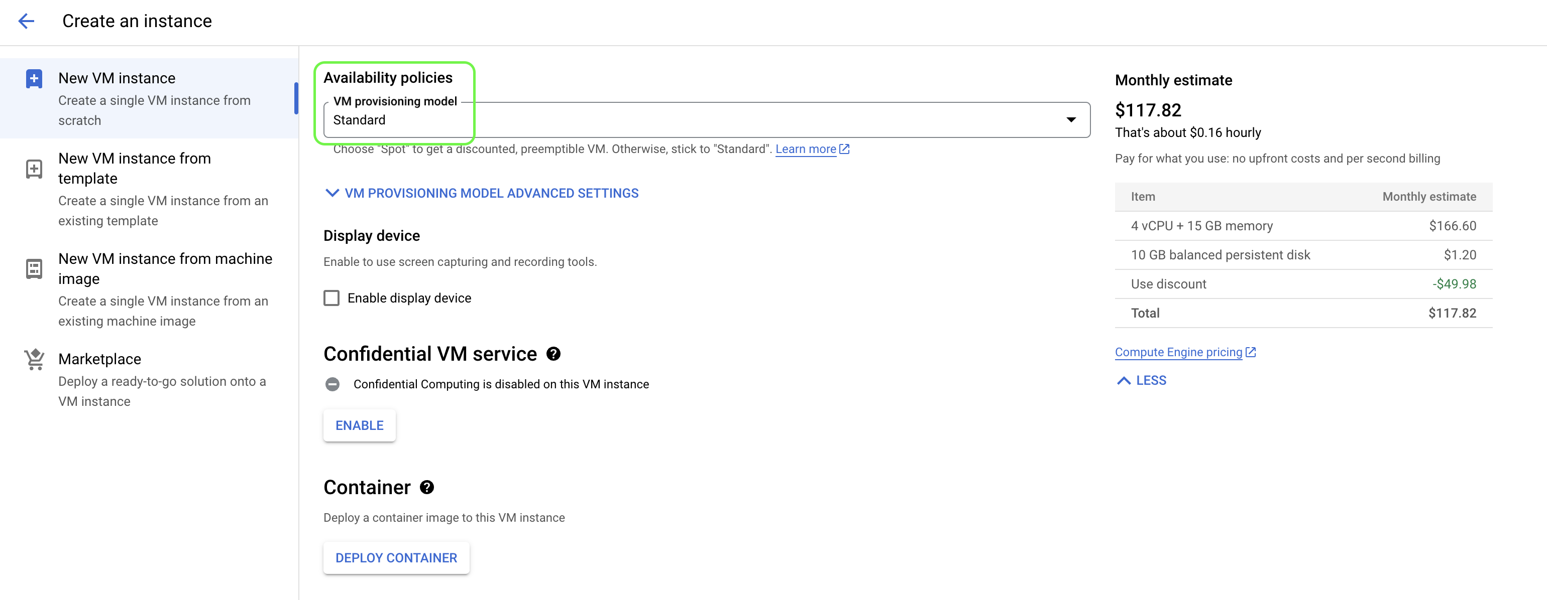
Figure
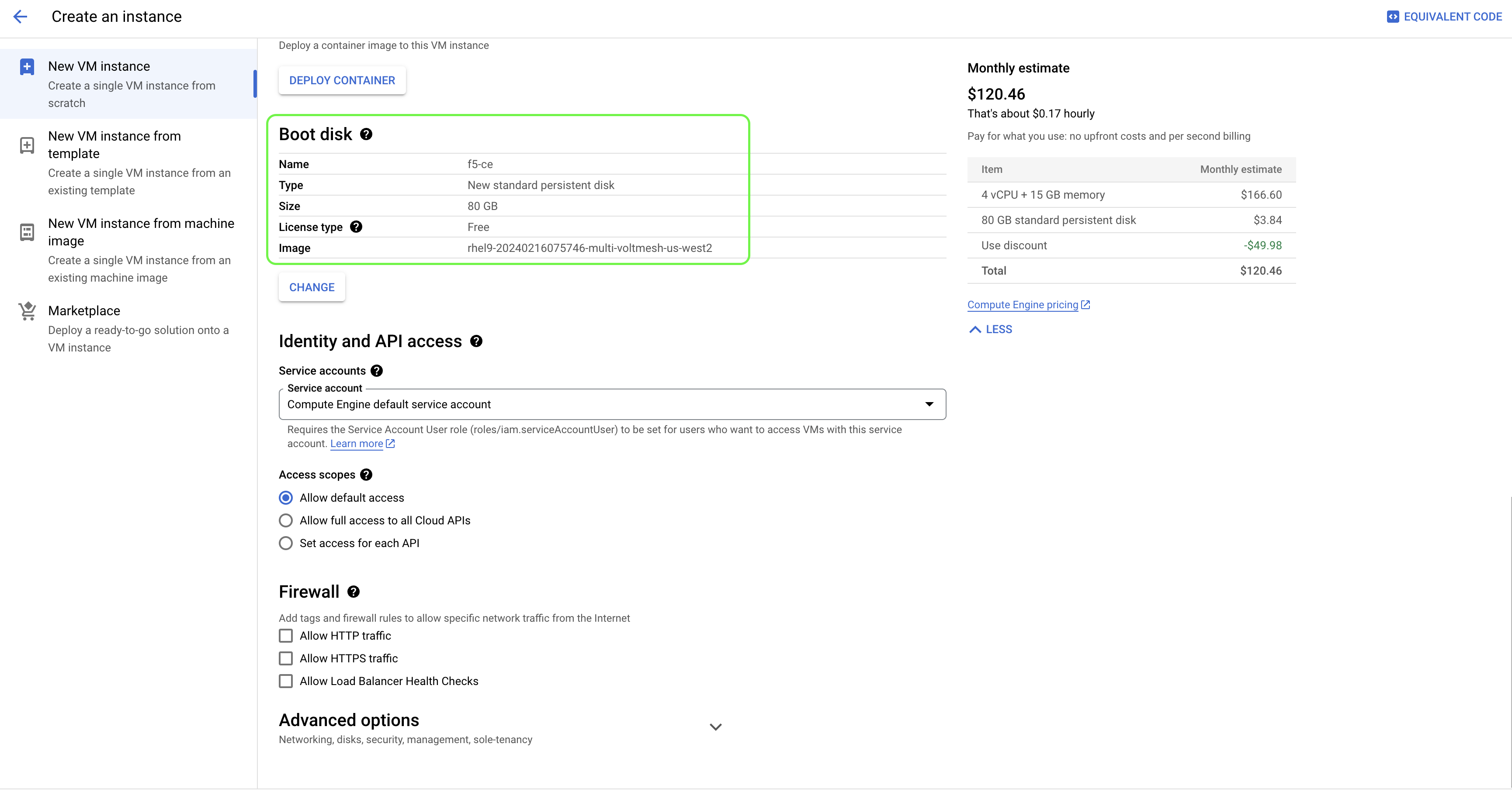
- Click
CHANGEto configureBoot disk. SelectCUSTOM IMAGEStab and use the previously uploaded F5 CE image withBoot disk typeasStandard persistent disk.
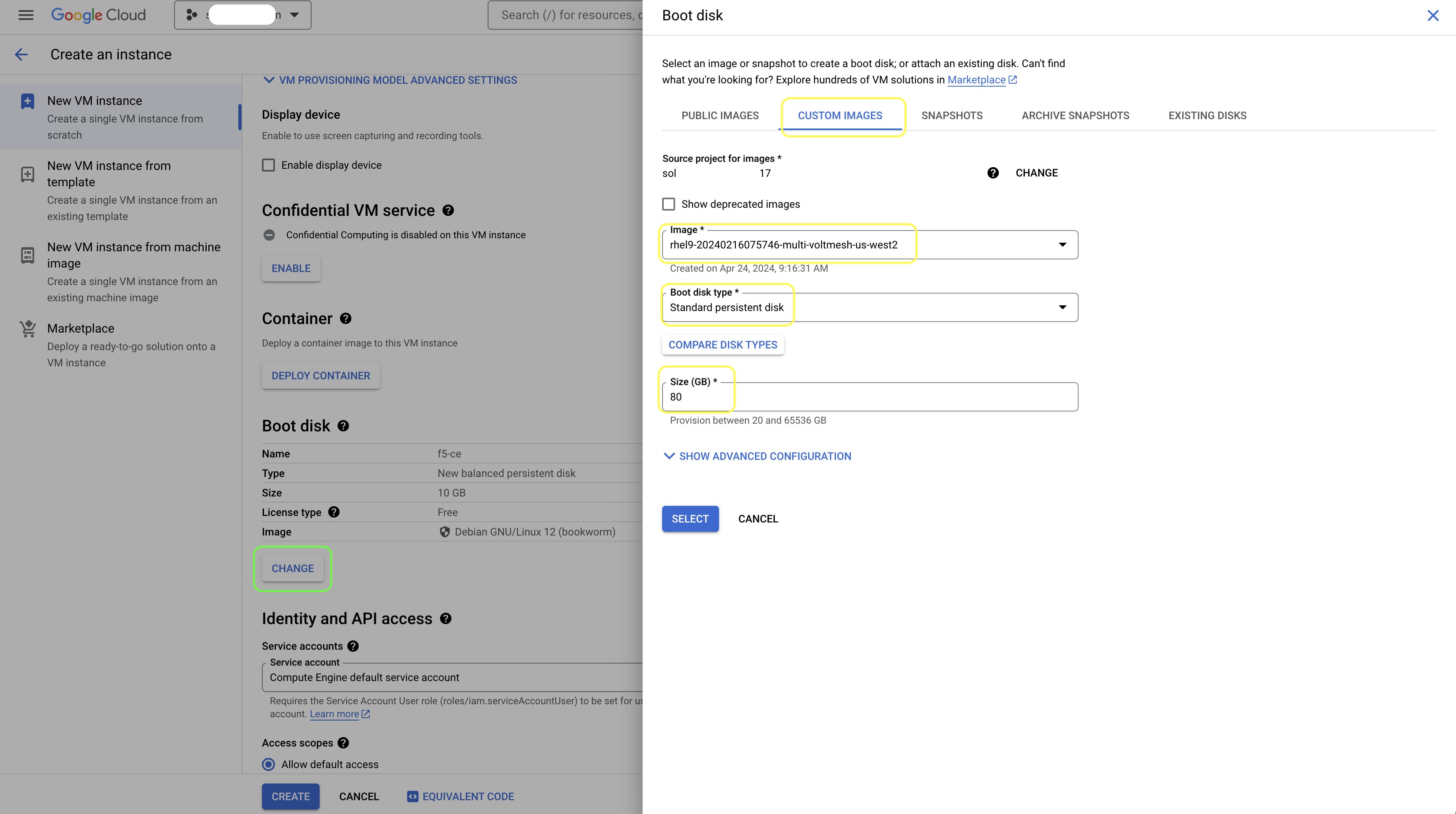
Figure
- Select default values for
Identity and API accessand empty firewall configuration.
Figure
- For
Networktags, use the network tag created during the VPC network configuration. EnableIP forwarding.
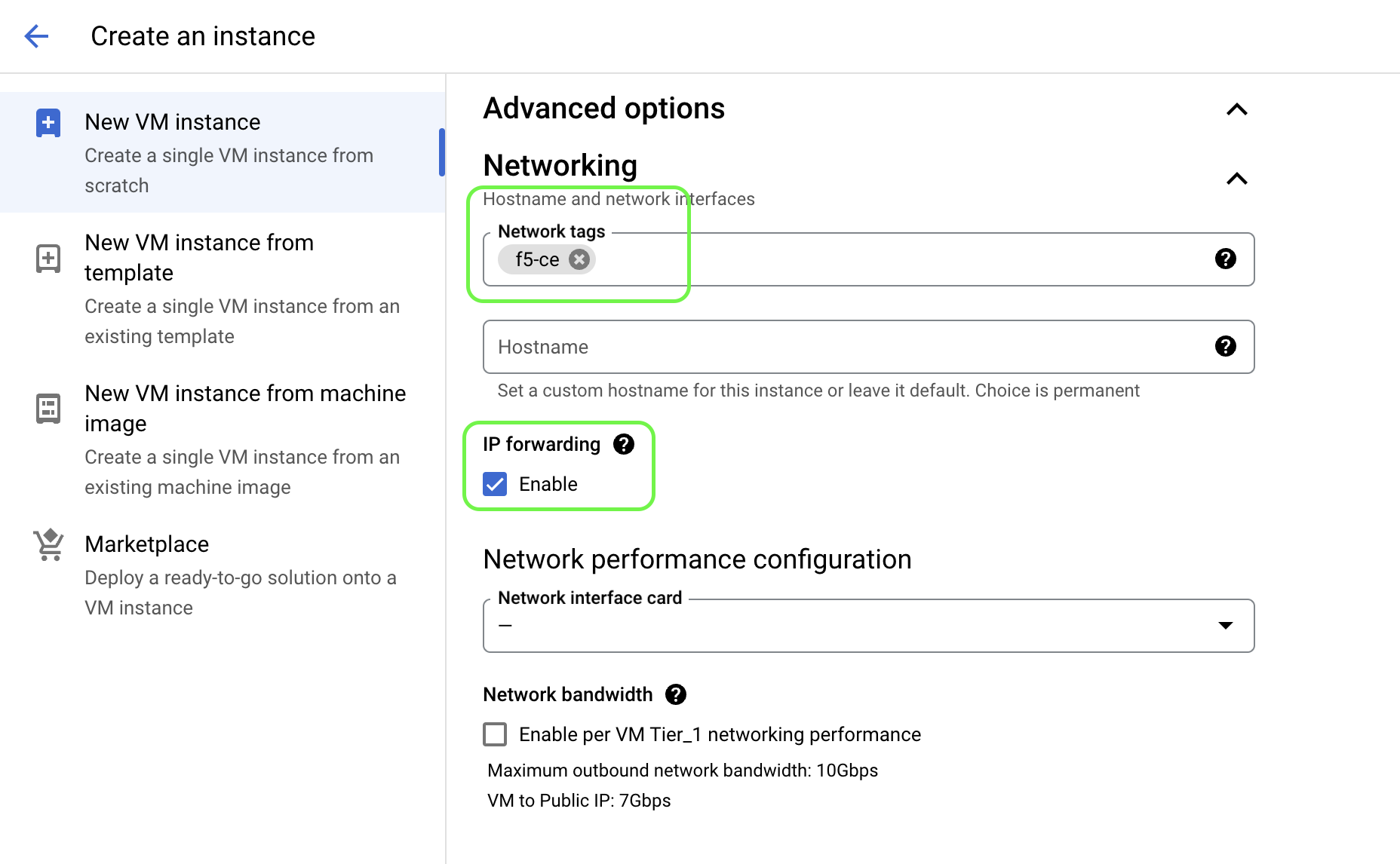
Figure
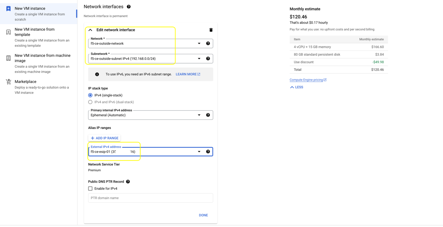
- In
Network interfacespage, first configure the Site Local Outside network that has Internet connectivity. Use the previously configured external static IP addresses for this interface. This interface will be discovered aseth0on the VM.
Figure
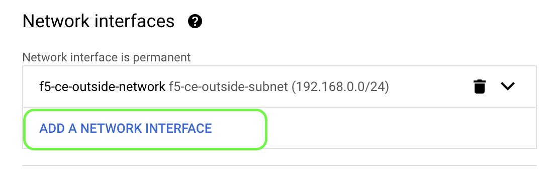
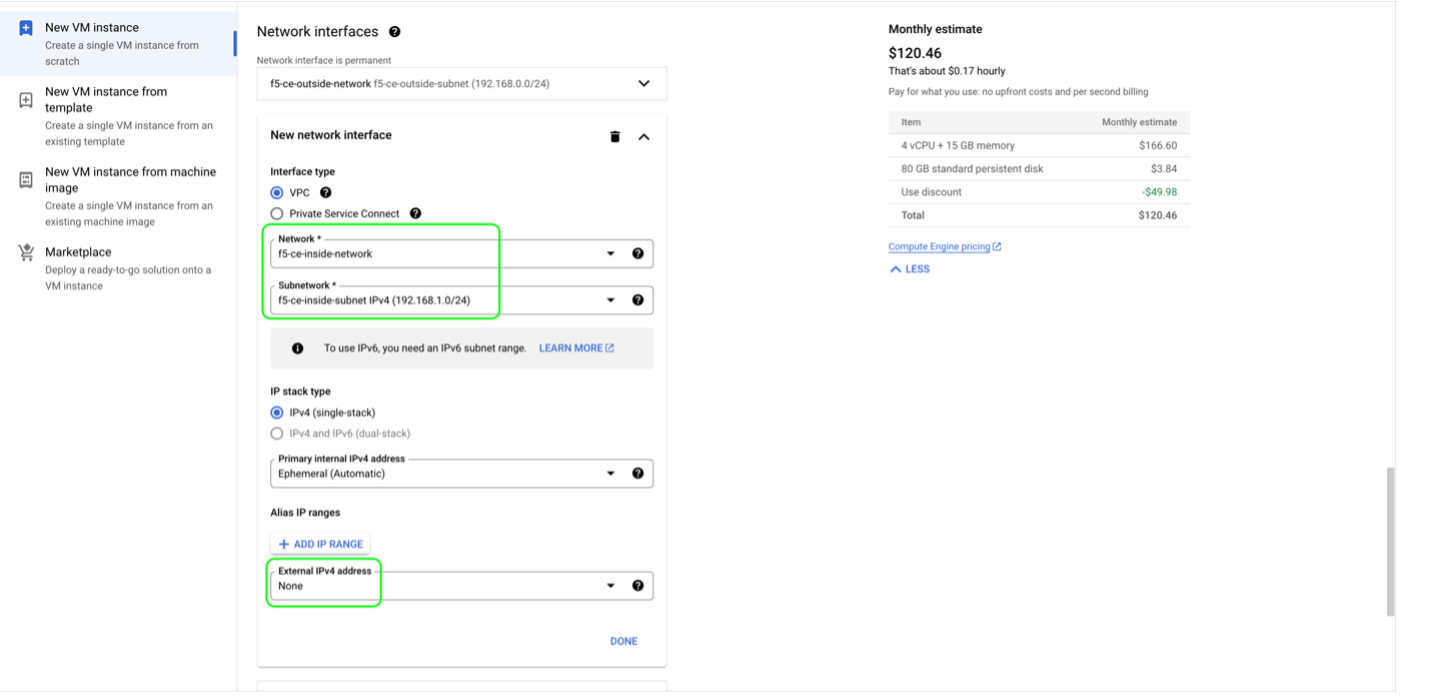
- Add another network interface for Site Local Inside network. This interface will be discovered as
eth1on the VM. The SLI network does not require Internet connectivity.
Figure
Figure
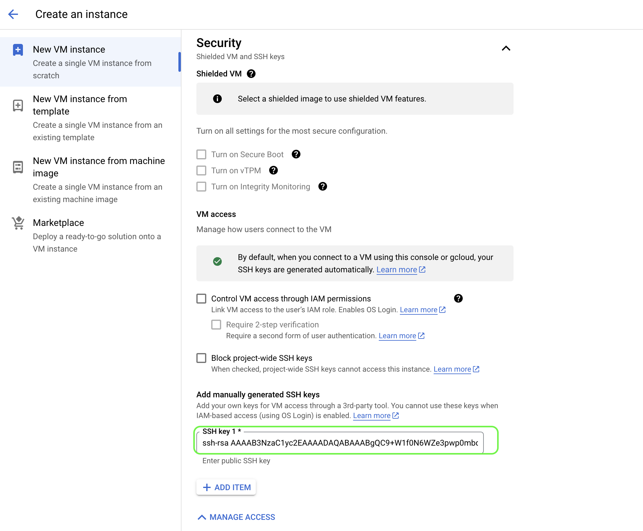
- In
Security, configure the SSH Key that was also used during user data configuration in a previous step.
Figure
- In
Management, add the two key-value pairs per the table above.
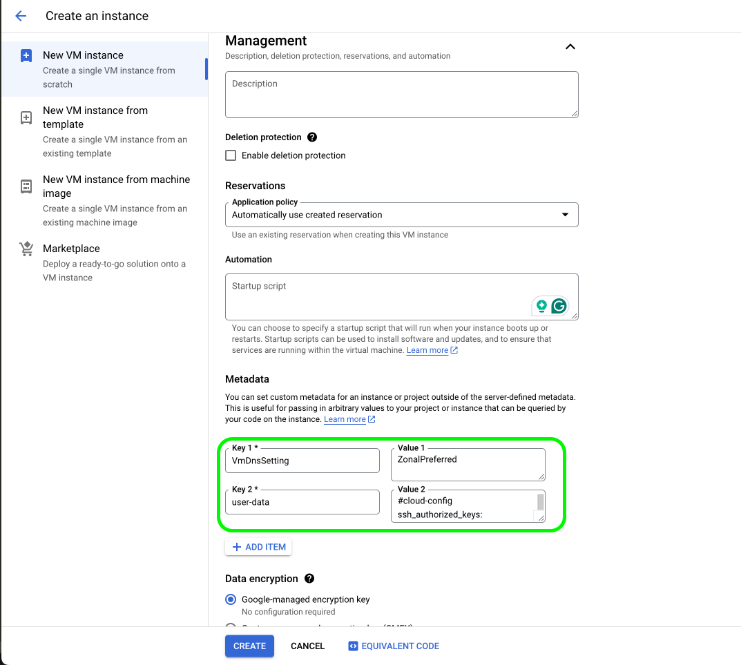
Figure
-
Click
CREATE. -
Repeat the above steps to create two more VM instances for node two and node three, respectively. Ensure that you are naming the instances (
f5-ce-node-2andf5-ce-node-3), their zones, and the external IP addresses correctly.
Deploy Single-Node Site
Follow these steps to create a single-node Secure Mesh Site.
Reserve External IP Address
Create an external IP address and give it a name. This IP address is used later for the virtual machine instance.
- In
VPC network, navigate toIP addresses. Then clickRESERVE EXTERNAL STATIC IP ADDRESS.
Figure: Reserve External IP Address
-
Enter a
Name. -
Under
Network Service Tier, select an option. -
Confirm
Regionand other parameters are configured correctly.
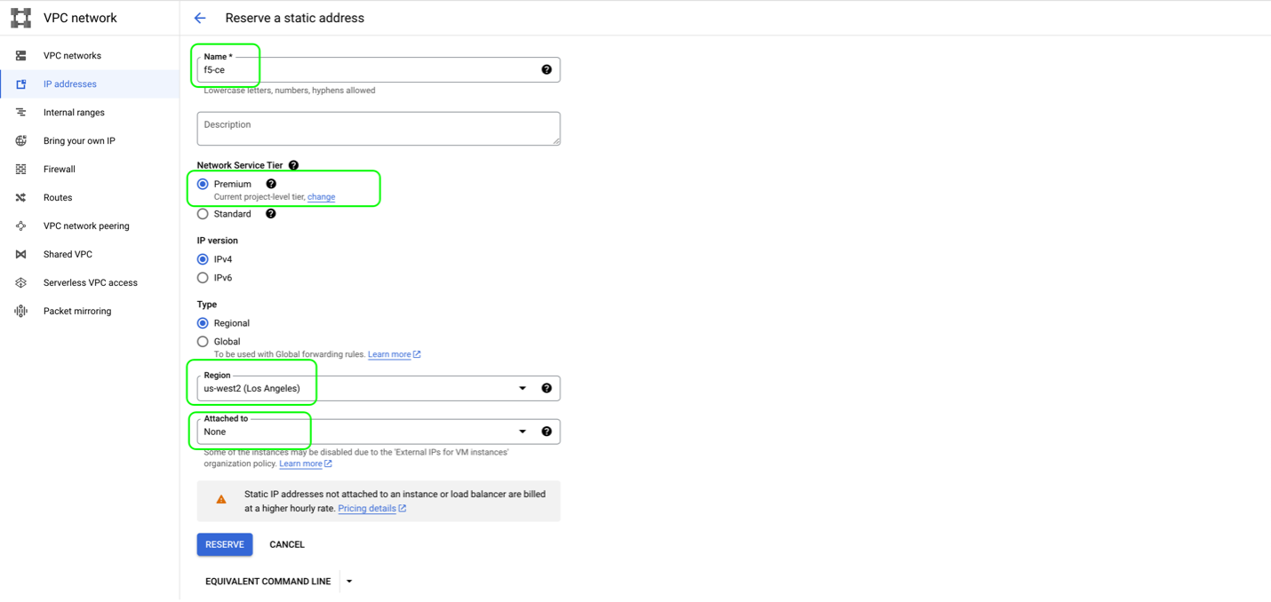
Figure: Reserve External IP Address
Create the F5 Customer Edge Node Instance
Create the F5 CE VM in GCP.
- In
Compute Engine, underVirtual machines, clickVM instances.
Figure
- Click
CREATE INSTANCE.
Figure
- Use the following table help with the example parameters:
| Parameter | Value | Notes |
|---|---|---|
| Name | f5-ce | Name of site. |
| Region | us-west2 | Region from GCP. |
| Zone | us-west2-a | Zone from GCP. |
| Machine Configuration/Machine Type | n2-standard-8 | Recommended instance types: See Customer Edge Site Sizing Reference. |
| VM Provisioning Model | Standard | Keep the default value. |
| Confidential VM Service | Disabled | Keep the default value. |
| Container | Disabled | Keep the default value. |
| Boot Disk: Custom Images | rhel9-20240216075746-multi-voltmesh-us-west2 | Select CUSTOM IMAGES and use the image uploaded on the previous step. |
| Boot Disk: Type | Standard persistent disk. | |
| Boot Disk: Size | 80 GB | Minimum disk space required is 80 GB for Mesh site and 100 GB for App Stack Site. |
| Identity and API access: Service account | Compute Engine default service account. | Keep the default value. |
| Identity and API access: Access scopes | Allow default access. | |
| Networking: Network tags | f5-ce | Use the one created for the egress network firewall rule. |
| Networking: IP forwarding | Enable | |
| SLO Network Interfaces: Network | f5-ce-outside-network | Outside network for eth0. |
| SLO Network Interfaces: Subnetwork | f5-ce-outside-subnet | Outside subnet created for outside network. |
| SLO Network Interfaces: IP stack type | IPv4 | |
| SLO Primary internal IPv4 address | Ephemeral (Automatic) | Use automatic IP addressing. |
| SLO External IPv4 address | f5-ce | Use the address created for the external IP address step. |
| SLI Network Interfaces: Network | f5-ce-inside-network | Inside network for eth1. |
| SLI Network Interfaces: Subnetwork | f5-ce-inside-subnet | Inside subnet created for inside network. |
| SLI Network Interfaces: IP stack type | IPv4 | |
| SLI Primary internal IPv4 address | Ephemeral (Automatic) | Use automatic IP addressing. |
| SLI External IPv4 address | None | No external IP address for eth1. |
| Security: SSH key1 | <your_ssh_public_key> | Add your SSH public key to access the site admin CLI. |
| Management: Metadata | Key 1: VmDnsSetting with Value 1: ZonePreferred | Zonal DNS mitigates the risk of cross-regional outages and improves the overall reliability of the VM. |
| Management: Metadata | Key 2: user-data with Value 2: <cloud-config> | Use the cloud config user data created previously. |
- Enter VM name with desired region and zone. For machine configuration,
N2 seriesis selected and theMachine typeisn2-standard-8.
Important: The name of the VM should not have "." in it. For example, the hostname can be node-0 or node0, but it cannot be node.f5.com since it is not supported. Your node VM name must adhere to DNS-1035 label requirements. This means the name must consist of lower case alphanumeric characters or “-“, start with an alphabetic character, and end with an alphanumeric character.
If configuring a multi-node site, each node hostname must be unique.
- Select default values for
Availability policies,Confidential VM serviceandContainer.
Figure
- Click
CHANGEto configureBoot disk. SelectCUSTOM IMAGEStab and use the previously uploaded F5 CE image withBoot disk typeasStandard persistent disk.
Figure
- Select default values for
Identity and API accessand empty firewall configuration.
Figure
- For
Networktags, use the network tag created during the VPC network configuration. EnableIP forwarding.
Figure
- In
Network interfacespage, first configure the Site Local Outside network that has Internet connectivity. Use the previously configured external static IP Address for this interface. This interface will be discovered aseth0on the VM.
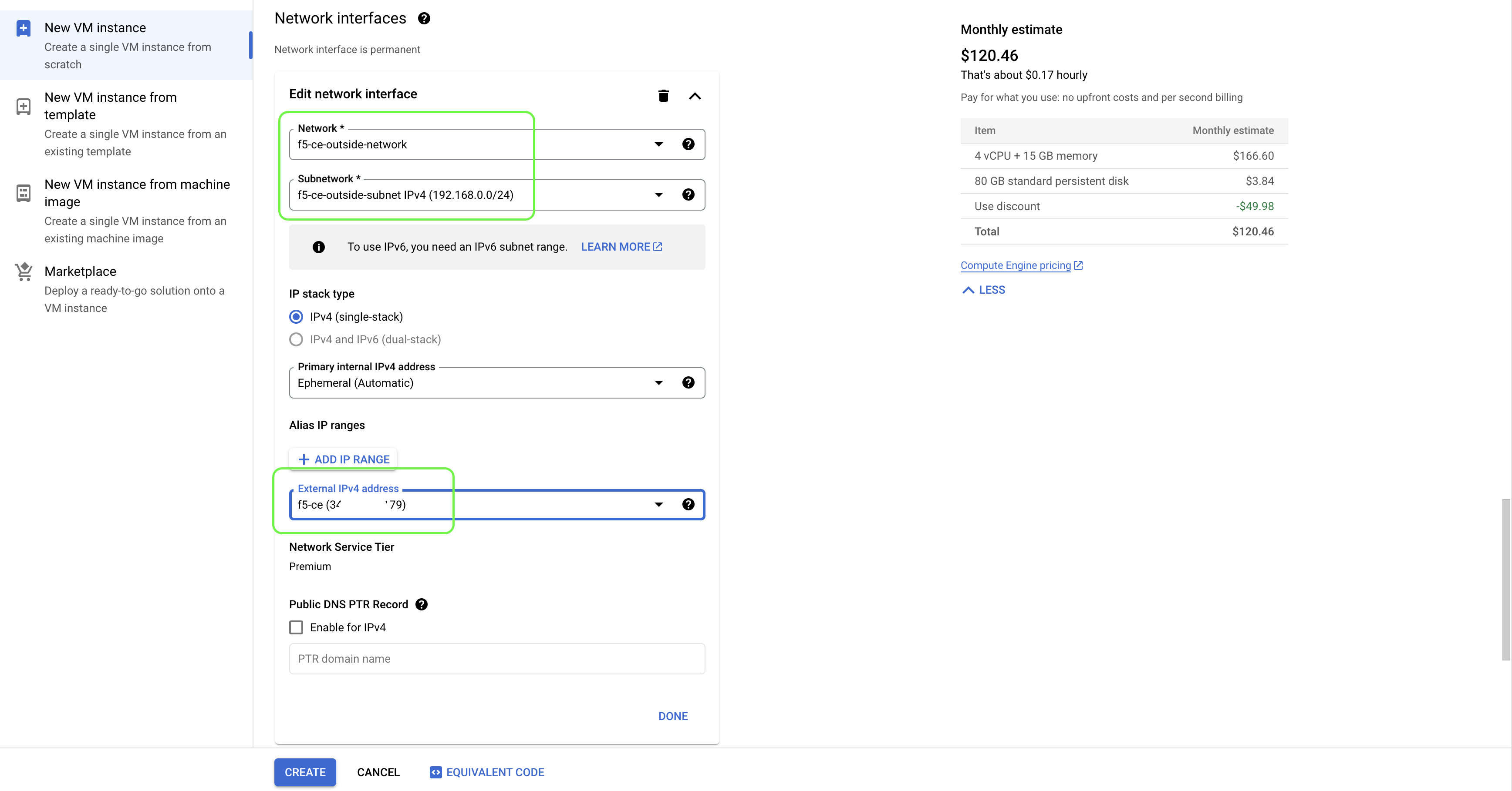
Figure
- Add another network interface for Site Local Inside network. This interface will be discovered as
eth1on the VM. The SLI network does not require Internet connectivity.
Figure

Figure
- In
Security, configure the SSH Key that was also used during user data configuration in a previous step.
Figure
- In
Management, add the two key-value pairs per the table above.
Figure
- Click
CREATE.
Create and Register Site
Follow the Secure Mesh or App Stack site creation guides to create a site object on F5 Distributed Cloud Console.
Troubleshooting
For troubleshooting and opening a support case, see the Troubleshooting Manual Site Deployment Registration Issues guide. It provides step-by-step instructions to debug and resolve the issues that may arise due to Distributed Cloud published Terraform errors, networking and security misconfiguration, or CE internal process issues. The guide also provides instructions for contacting the F5 Distributed Cloud Support Team if you are unable to resolve the issue.
Concepts
- System Overview
- Core Concepts
- Networking
- F5 Distributed Cloud - Customer Edge
- F5 Distributed Cloud Site
References
On this page:
- Objective
- Site Types and Scenarios
- Considerations for Sites Behind NAT Gateway
- Prerequisites
- Procedure
- Create GCP VPC Networks
- Create Firewall Rules
- Import and Configure F5 CE Image
- Create Site Token
- Configure User Data for Virtual Machine
- Deploy Multi-Node Site
- Reserve External IP Addresses
- Create the F5 Customer Edge Node Instances
- Deploy Single-Node Site
- Reserve External IP Address
- Create the F5 Customer Edge Node Instance
- Create and Register Site
- Troubleshooting
- Concepts
- References