Create App Stack Site
Objective
This document provides instructions on how to install F5® Distributed Cloud single-node or multi-node F5 Distributed Cloud App Stack sites on clusters of private Data Center (DC) devices. An App Stack site is a Distributed Cloud Customer Edge (CE) site engineered specifically for the purpose of managing DC clusters. The F5 Distributed Cloud Platform also supports creating physical K8s (also called managed K8s) clusters for managing your applications on the created App Stack sites.
Clusters of private DCs that are set up on geographically separated locations require an established direct communication link with each member of the cluster. An App Stack site helps achieve that while ensuring safety and reliability. You can define a DC cluster group in an App Stack site to which member nodes can be added dynamically. Such added members become part of the cluster group and automatically get full mesh connectivity with all other members of the group.
Using the instructions provided in this document, you can deploy a single-node or multi-node App Stack site on your private DC, define a cluster group, and add members to the cluster group. You can also enable the local API access for the managed K8s running on the sites so that it can be used like regular K8s.
App Stack Site vs Other CE Sites
The App Stack site differs from the regular Distributed Cloud CE site that can be deployed with App Stack. An App Stack site simplifies the task of managing distributed apps across DC clusters while offering the option to establish full mesh connectivity among themselves. In the case of regular sites with App Stack functionality, you must explicitly create and manage site mesh groups for that purpose. With an App Stack site, you just need to add the site to the DC cluster group and connectivity is automatically established.
Also, an App Stack site provides support to manage local K8s while controlling communication between services of different namespaces. While regular Distributed Cloud sites provide virtual K8s (vK8s), the vK8s is per namespace per site, and managed local K8s is deployed across all namespaces of an App Stack site with a single kubeconfig. Therefore, if you require the ability to manage distributed apps across your private DC clusters with full mesh connectivity, an App Stack site with managed K8s is useful. For other requirements, you can use regular CE sites.
Reference Architecture
This reference architecture shows the recommended practice for setting up geographically distributed DC clusters using App Stack sites, privately connecting them using DC cluster group, and enabling managed K8s for deploying apps in those clusters.
The following image shows a sample reference architecture of the App Stack DC cluster site.
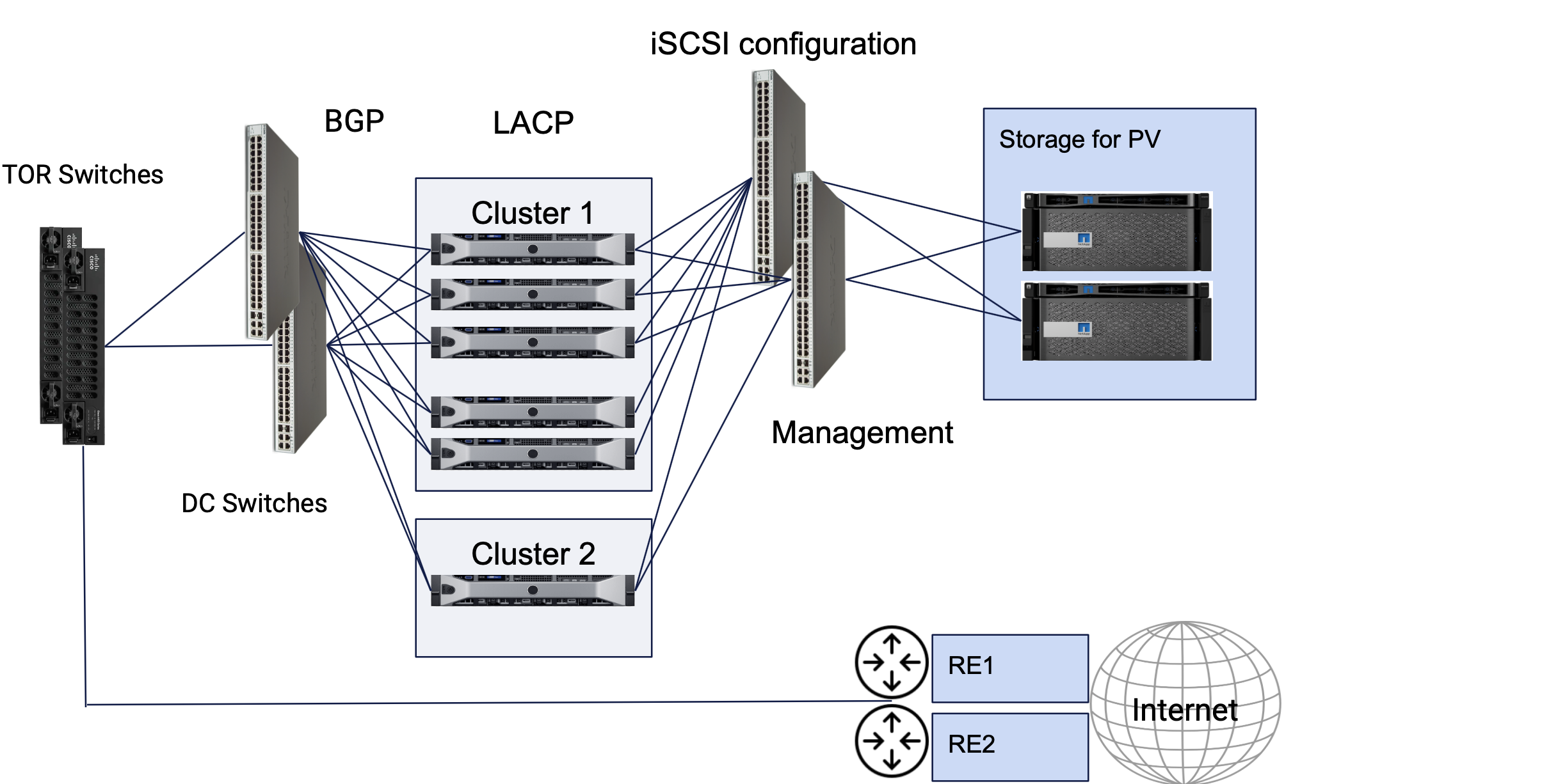
Figure: App Stack DC Cluster Site Reference Architecture
The DC clusters represent App Stack sites. These consist of interfaces towards storage network, interfaces in LACP towards DC switches, and dedicated or non-dedicated management interfaces. An App Stack site supports storage classes with dynamic PVCs. Bonded interfaces are also supported with bond interfaces for regular use in the case of a dedicated management interface. In the case of non-dedicated management interfaces, the fallback interface for internet connectivity in a bonded interface which must be assigned with a static IP address. The example image also shows TOR switches that can be connected with a single bond interface using MC-LAG or with 2 bond interfaces at L3 level. An App Stack site also supports establishing BGP peering with the TORs.
Bonding of interfaces is supported in LACP active/active or active/backup modes.
The following image shows sample reference deployment of an App Stack DC cluster sites that are deployed at different geographies.
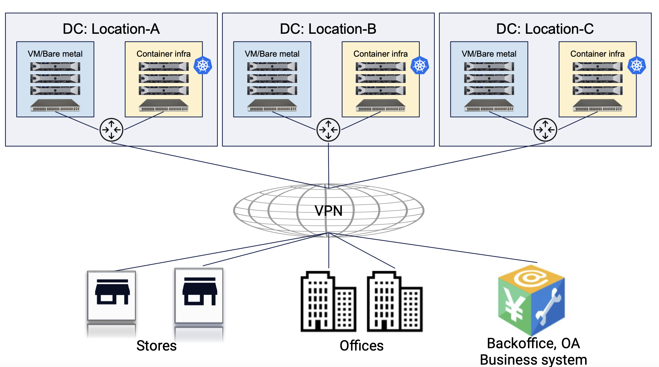
Figure: App Stack DC Cluster Site Reference Deployment
The apps deployed in the managed K8s clusters in these sites can directly communicate with each other in CI/CD use cases or users can obtain access to managed K8s API using the Kubeconfig.
The following image shows service interaction for service deployed in different DC cluster sites:
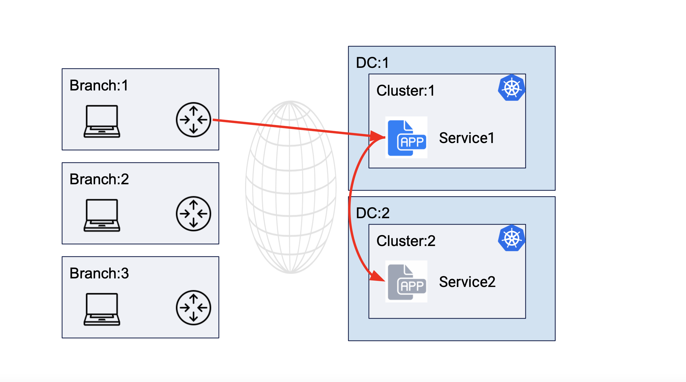
Figure: Service Communication Between Clusters of Different DCs
The following image shows service interaction for service deployed in the same DC cluster site:
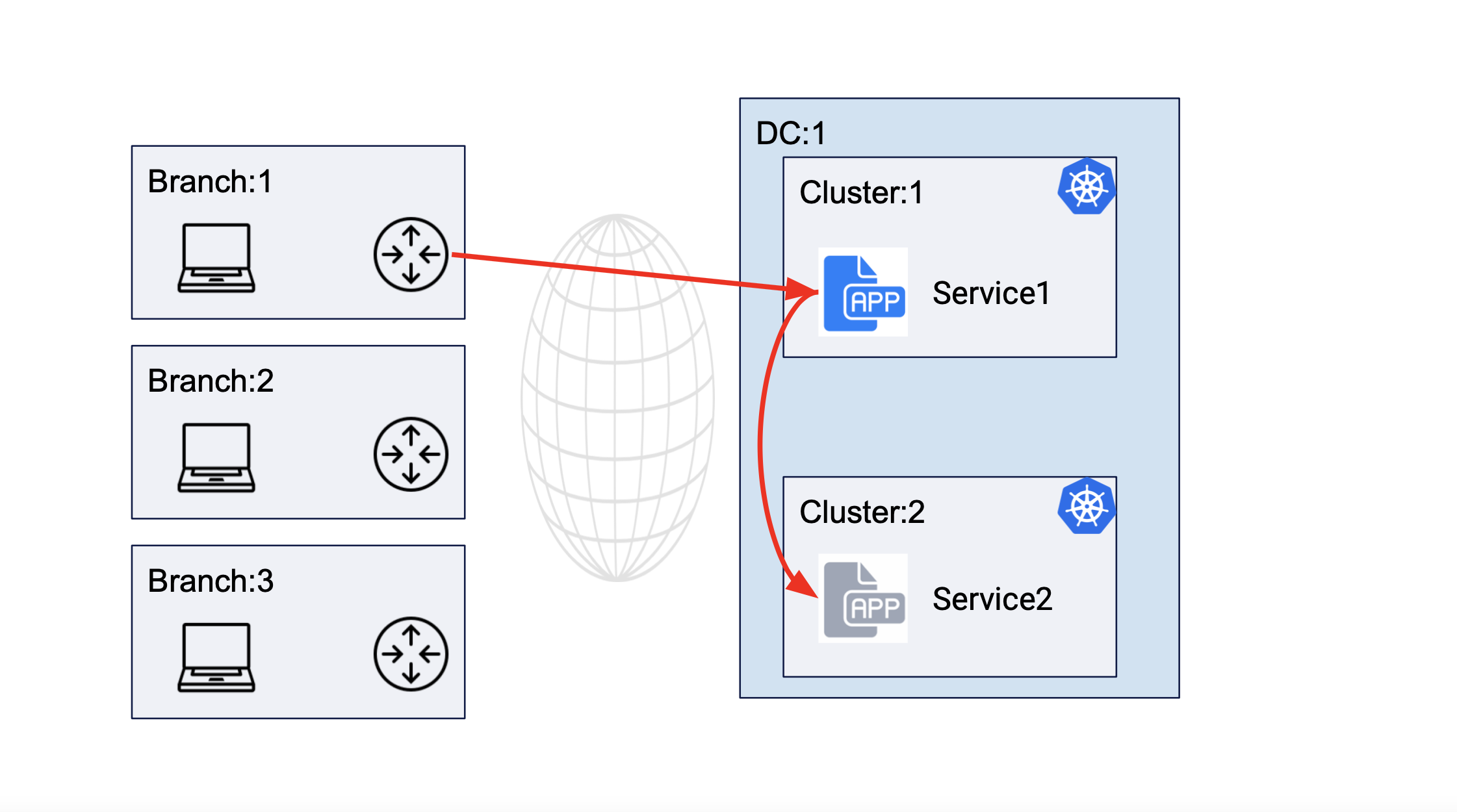
Figure: Service Communication Between Clusters of Same DC
The following image shows service deployment in active/active and active/standby mode for remote clients:
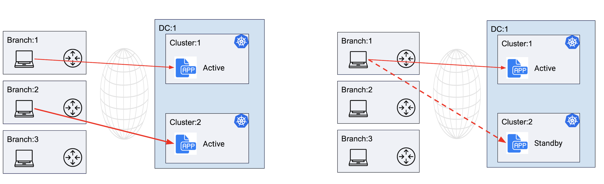
Figure: Service Deployment in Active-Active and Active-Standby Modes
Note: For instruction on accessing managed K8s clusters and deploying apps, see Create and Deploy Managed K8s guide.
Prerequisites
-
An F5 Distributed Cloud Account. If you do not have an account, see Getting Started with Console.
-
One or more physical DC devices consisting of interfaces with Internet reachability. An App Stack site is supported only for the F5 IGW, ISV, and Dell Edger 640 Series devices.
-
Resources required per node: Minimum 8 vCPUs, 32 GB RAM, and 100 GB disk storage. For a full listing of the resources required, see the Customer Edge Site Sizing Reference guide. All the nodes in a given CE Site should have the same resources regarding the compute, memory, and disk storage. When deploying in cloud environments, these nodes should use the same instance flavor.
-
Allow traffic from and to the Distributed Cloud public IP addresses to your network and allowlist related domain names. See F5 Customer Edge IP Address and Domain Reference for Firewall or Proxy Settings guide for the list of IP addresses and domain names.
-
Internet Control Message Protocol (ICMP) needs to be opened between the CE nodes on the Site Local Outside (SLO) interfaces. This is needed to ensure intra-cluster communication checks.
Important: After you deploy the CE Site, the IP address for the SLO interface cannot be changed. Also, the MAC address cannot be changed.
Deploy Site
Perform the steps provided in the following chapters to deploy an App Stack site.
Create App Stack Site Object
Log into F5 Distributed Cloud Console and perform the following steps:
Step 1: Start creating an App Stack site object.
-
In
Multi-Cloud Network Connectworkspace, navigate toManage>Site Management>App Stack Sites. -
Select
Add App Stack Siteto open the App Stack site configuration form.
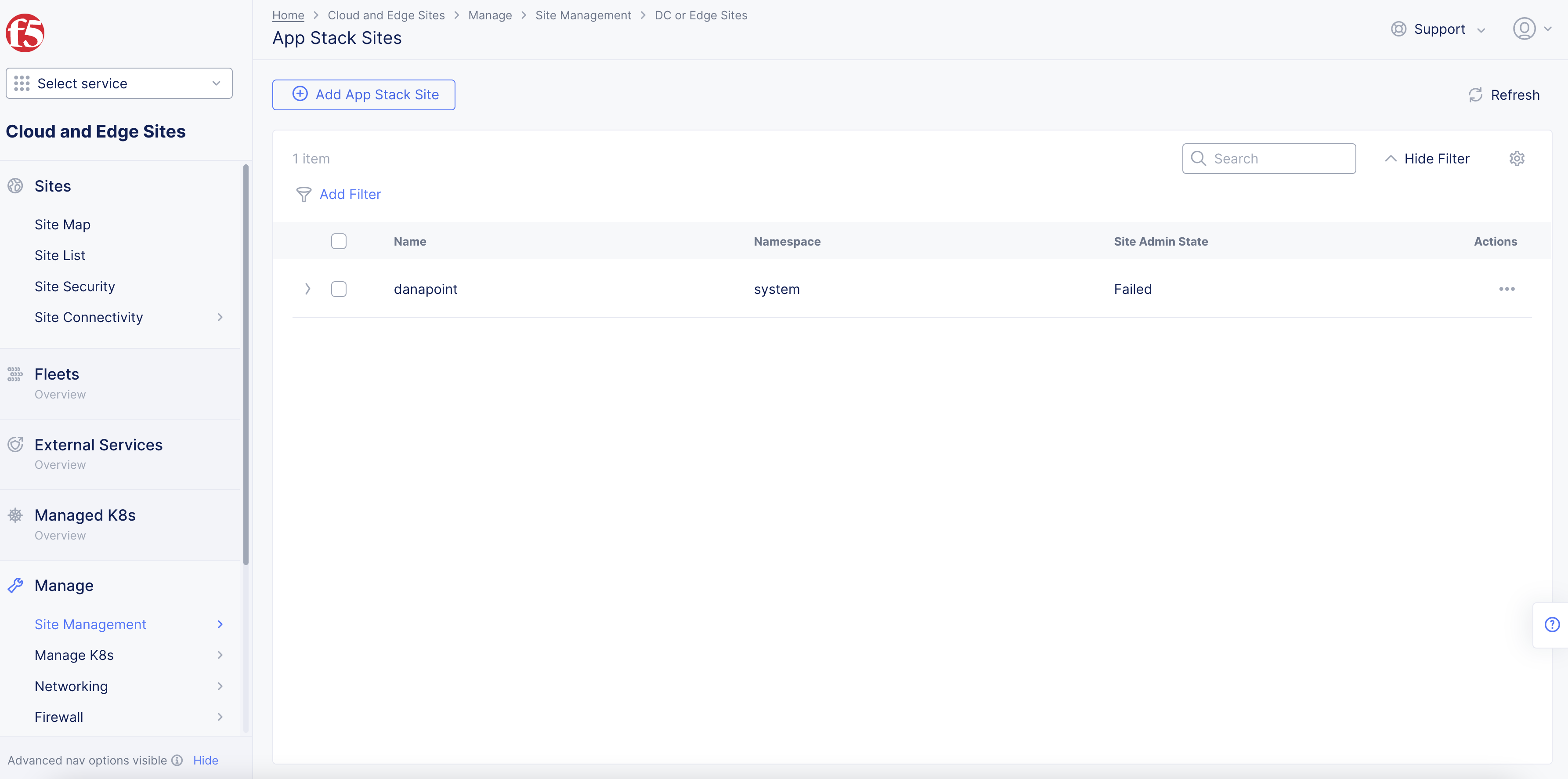
Figure: Navigate to App Stack Site Configuration
-
Enter a name in the
Metadatasection for your App Stack site object. -
Optionally, select labels and add a description.
Note: Adding a Fleet label to an App Stack site is not supported.
Step 2: Set the fields for the basic configuration section.
-
From the
Generic Server Certified Hardwaremenu, select an option. Theisv-8000-series-voltstack-combois selected by default. -
Enter the names of the master nodes in the
List of Master Nodesfield. SelectAdd itemto add more than one entry. Only a single node or 3 master nodes are supported. -
Optionally, enter the names of worker nodes in the
List of Worker Nodesfield. SelectAdd itemto add more than one entry. -
Optionally, enter the following fields:
-
Geographical Address: This derives geographical coordinates.
-
Coordinates: Latitude and longitude.
-
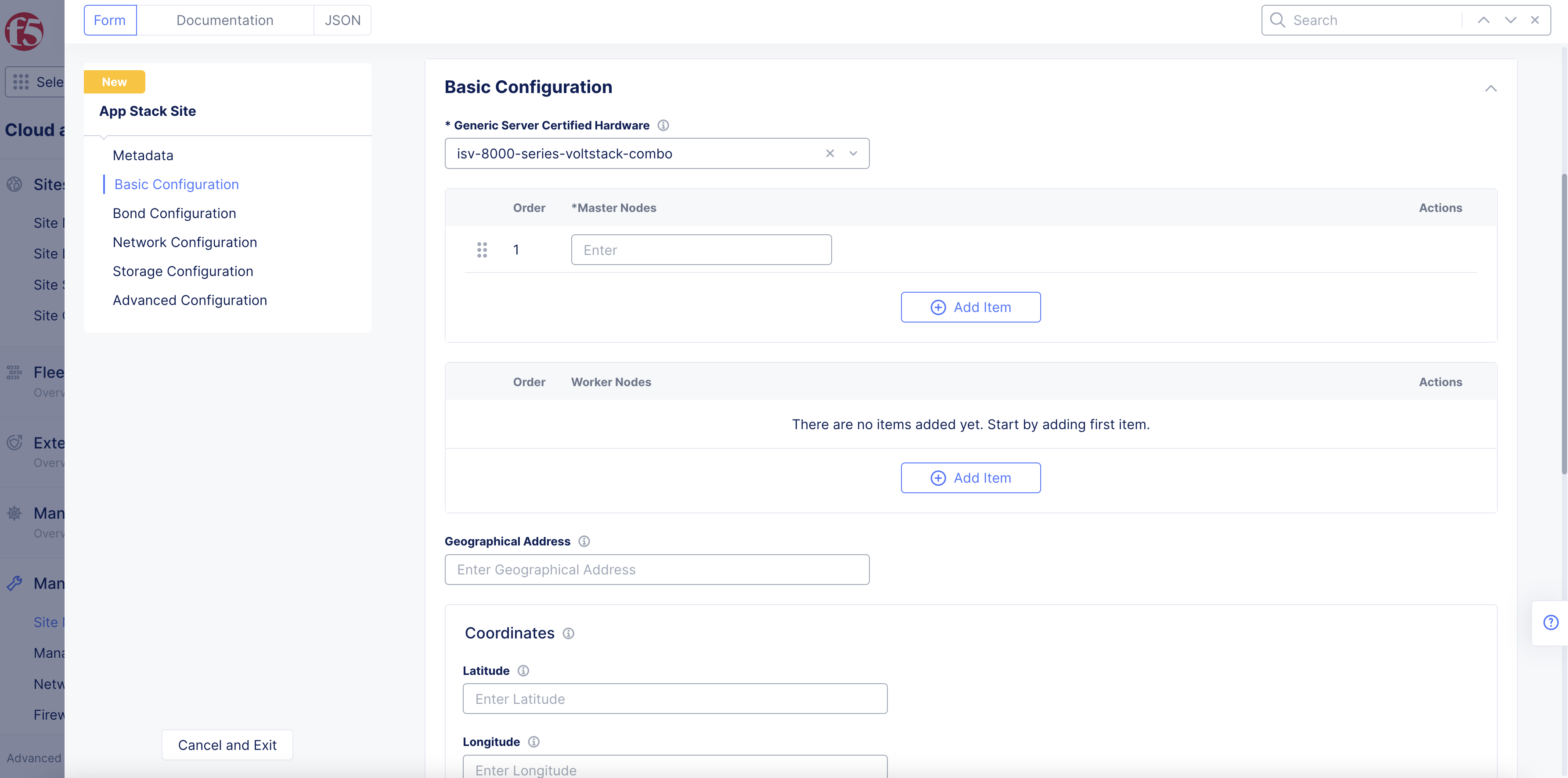
Figure: App Stack Site Basic Configuration Section
Step 3: Configure bond interfaces.
In the Bond Configuration section, perform the following:
- From the
Select Bond Configurationmenu, selectConfigure Bond Interfaces.
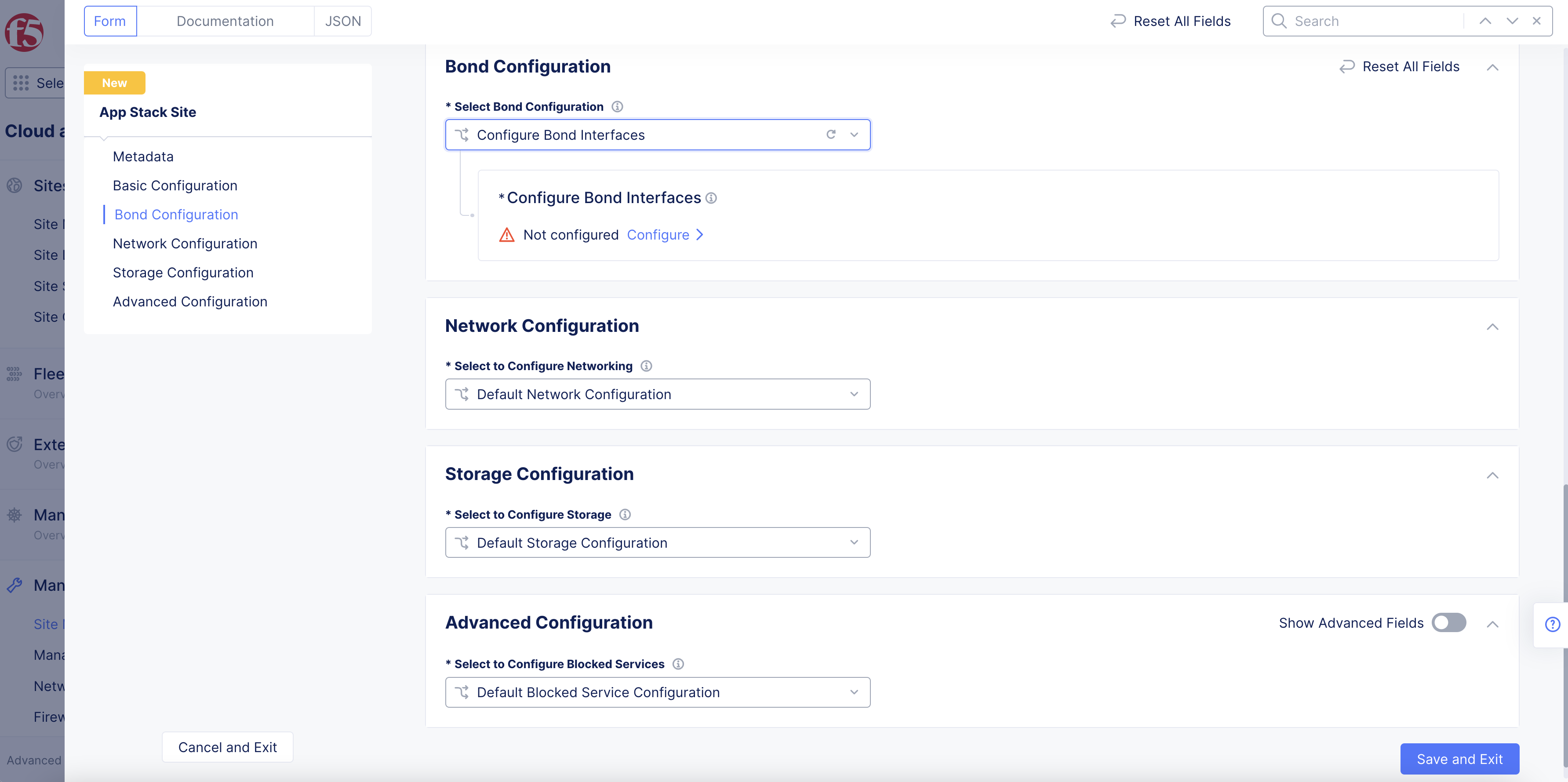
Figure: Bond Configuration Section
-
Select
Configureto open bond interface configuration page. -
Select
Add Itemunder theBond Devices Listfield.
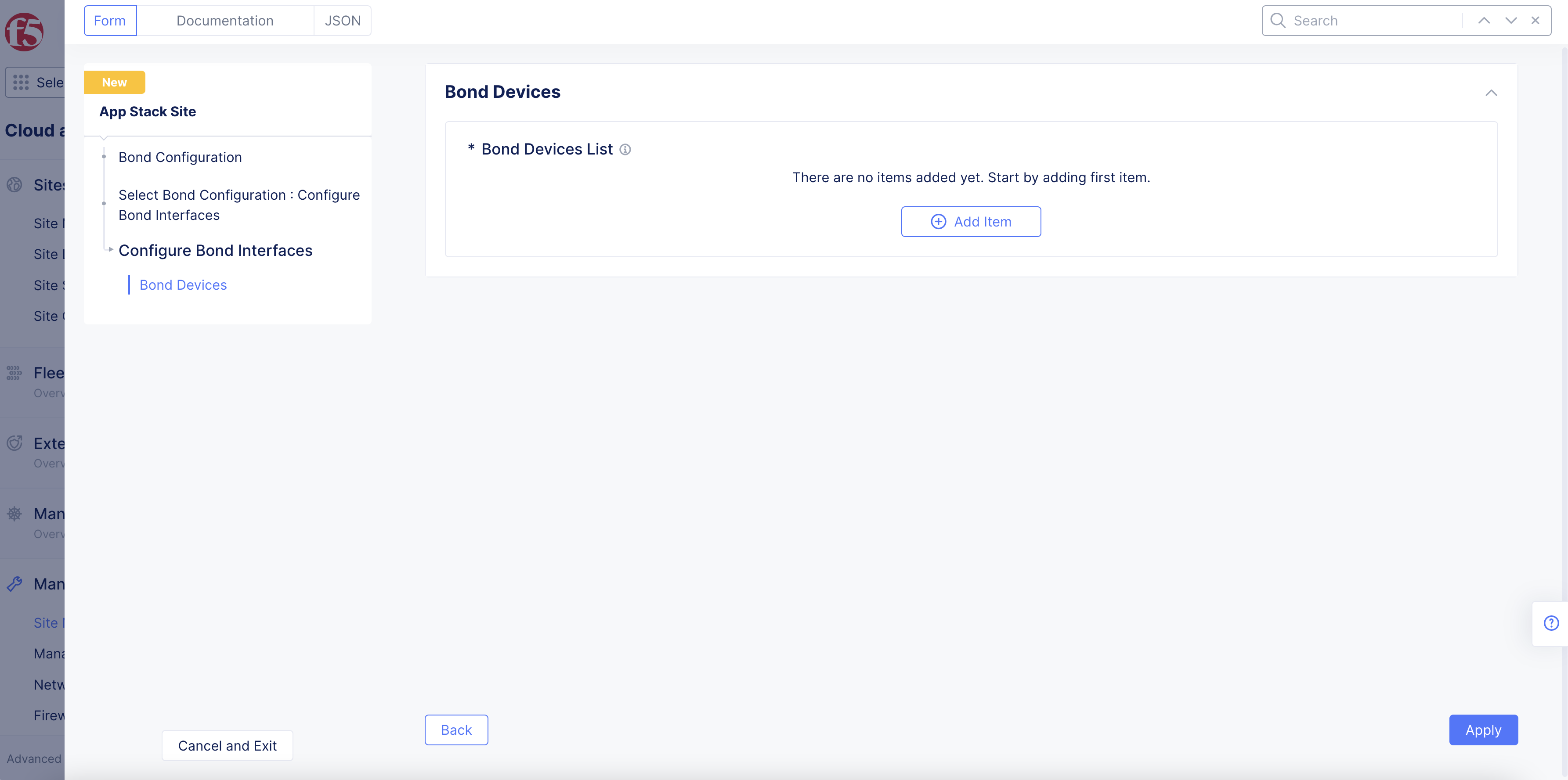
Figure: Bond Devices Section
-
Select on the
Bond Device Namefield and selectSee Common Values. You can also type a custom name and clickAdd itemto set the device name while also adding it to the existing options. -
Select on the
Member Ethernet Devicesfield and selectSee Common Valuesfor the Ethernet device that is part of this bond. UseAdd itemoption to add more devices. -
From the
Select Bond Modemenu, select the bonding mode.LACP (802.3ad)is selected by default for the bonding mode with the default LACP packet interval as 30 seconds. You can set the bond mode toActive/Backupto set the bond members function in active and backup combination.
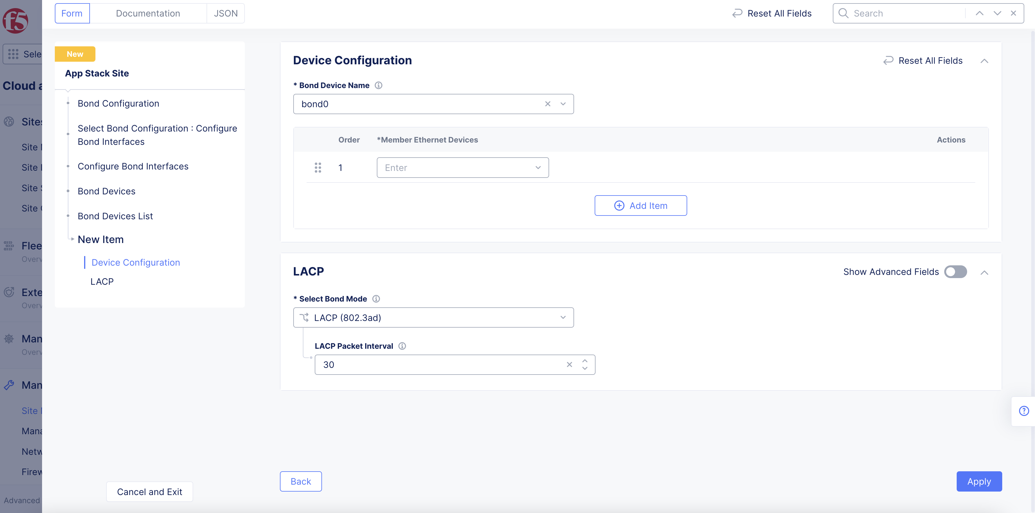
Figure: Bond Devices List
- Select
Add Item.
Note: Use the
Add itemoption in theBond Devices Listto add more than one bond device.
- Select
Applyin theBond Devicespage to apply the bond configuration.
Step 4: Perform network configuration.
-
In the
Network Configurationsection, perform the following:-
Select
Custom Network Configurationfrom theSelect to Configure Networkingmenu. -
Select
Configureto open the network configuration page.
-
Step 4.1: Perform site local network configuration.
Site local network is applied with default configuration. Perform the following set of steps to apply custom configuration:
-
Select
Configure Site Local Networkfrom theSelect Configuration For Site Local Networkmenu. -
Select
Configure. -
Optionally, set labels for the
Network Labelsfield in theNetwork Metadatasection. -
Optionally, select
Show Advanced Fieldsin theStatic Routessection. -
Select
Manage Static Routesfrom theManage Static Routesmenu. -
Select
Add Itemand perform the following:-
Enter IP prefixes for the
IP Prefixessection. These prefixes will mapped to the same next-hop and attributes. -
Select
IP AddressorInterfaceorDefault Gatewayfrom theSelect Type of Next Hopmenu and specify IP address or interface accordingly. In the case ofInterface, you can select an existing interface or create a new interface using the options for the interface field. -
Optionally, select one or more options for the
Attributesfield to set attributes for the static route. -
Select
Add Item.
-
-
Optionally, enable
Show Advanced Fieldsoption in theDc Cluster Groupsection and perform the following:-
Select
Member of DC Cluster Groupfrom theSelect DC Cluster Groupmenu. -
In the
Member of DC Cluster Groupfield, select a DC cluster group. You can also selectCreate New DC Cluster Groupto create a new cluster group. Performing this adds this site to a DC cluster group, enabling full connectivity between the members of the group.
-
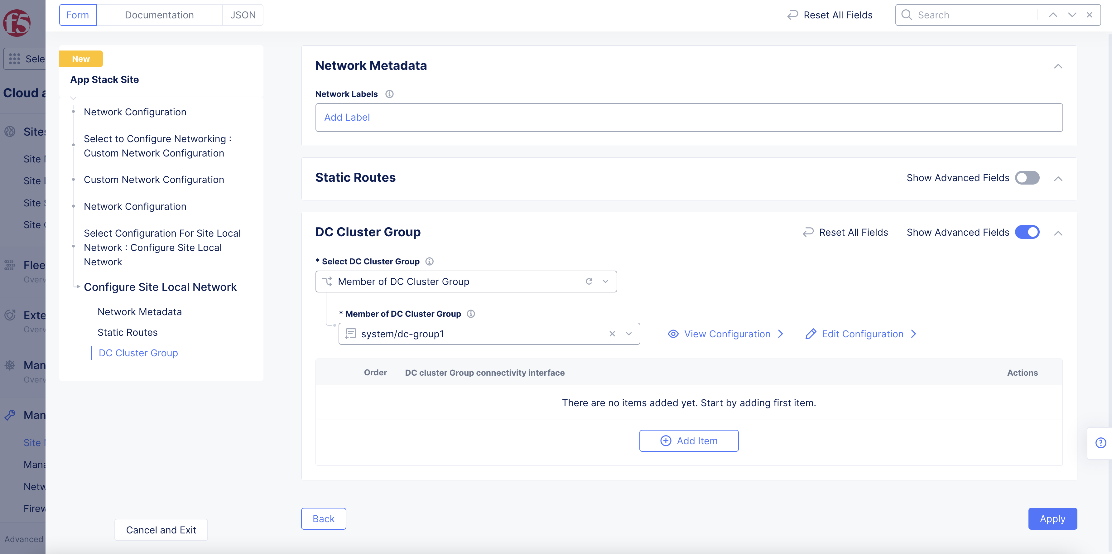
Figure: Site Local Network Configuration
- Select
Apply.
Note: For more information, see the Configure DC Cluster Group guide.
Step 4.2: Perform interface configuration.
Bootstrap interface configuration is applied by default, and it is based on the certified hardware.
Perform the following to apply custom interface configuration:
-
Select
List of Interfacefrom theSelect Interface Configurationmenu. -
Click
Configure. This opens another interface list configuration page. -
Select
Add Itemin theList of Interfacetable. -
Optionally, enter an interface description and select labels.
-
Select an option from the
Interface Config Typemenu, and set one of the interface types using the following instructions:
Ethernet Interface:
-
Select
Ethernet Interfaceand clickConfigure. This opens Ethernet interface configuration page. -
Select an option from the
Ethernet Devicemenu usingSee Common Values. You can also type a custom name to set the device name while also adding it to the existing options. -
Select
Cluster, All Nodes of the SiteorSpecific Nodefrom theSelect Configuration for Cluster or Specific Nodemenu. In case of specific node, select the specific node from the displayed options of theSpecific Nodefield. You can also type a custom name to set the device name while also adding it to the existing options. -
Select
UntaggedorVLAN Idfrom theSelect Untagged or VLAN taggedmenu. In case of VLAN ID, enter the VLAN ID in theVLAN Idfield. -
Select an option from the
Select Interface Address Methodmenu in theIP Configurationsection. TheDHCP Clientis selected by default. In case you select a DHCP server, clickConfigureand set the DHCP server configuration per the options displayed on the DHCP server configuration page and clickApply. This example shows the interface as DHCP client for brevity. -
Select site local outside or site local inside network from the
Select Virtual Networkmenu in theVirtual Networksection.Site Local Network (Outside)is selected by default. -
Select if the interface is primary from the
Select Primary Interfacemenu. Default is not a primary interface. Ensure that you set only one interface as primary. -
Select
Apply.
Dedicated Interface:
-
Select
Dedicated Interfacefrom theInterface Config Typemenu. -
Select a device name from the
Interface Devicemenu usingSee Common Values. You can also type a custom name to set the device name while also adding it to the existing options. -
Select
Cluster, All Nodes of the SiteorSpecific Nodefrom theSelect Configuration for Cluster or Specific Nodemenu. In case of specific node, select the specific node from the displayed options from theSpecific Nodemenu. You can also type a custom name to set the device name while also adding it to the existing options. -
Select if the interface is primary in the
Select Primary Interfacefield. Default is not a primary interface. Ensure that you set only one interface as primary. -
Select
Add Item. -
Optionally, add more than one interface using the
Add itemoption in theList of Interfacepage. -
Select
Apply.
Step 4.3: Perform security configuration.
In case of security configuration, the firewall policies and forward policies are disabled by default.
In the Security Configuration section, perform the following to apply network and forward policies:
-
From the
Firewall Policymenu, optionally add a firewall policy by selectingActive Firewall PoliciesorActive Enhanced Firewall Policies. Select an existing firewall policy, or selectAdd Itemto create and apply a firewall policy orConfigurefor an enhanced version. -
From the
Forward Proxymenu, select an option:-
Select
Enable Forward Proxy With Allow All Policyto allow all requests. -
Select
Enable Forward Proxy and Manage Policiesto apply specific forward proxy policies. Select a forward proxy policy from theForward Proxy Policiesmenu. You can also create and apply a new forward proxy policy using theAdd Itemoption. You can apply more than one forward proxy policy using theAdd Itemoption.
-
-
Optionally, you can configure global networks in the
Global Connectionssection and BGP settings in theAdvanced Configurationsection. This example does not include the configuration for these two configuration options.
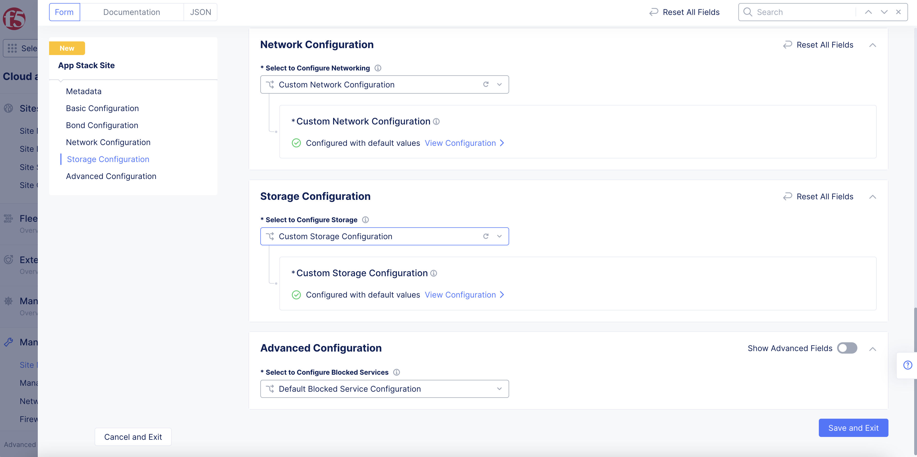
Step 5: Optionally, perform storage configuration.
In the Storage Configuration section, perform the following steps to configure storage interfaces for your App Stack site:
- From the
Configure Storagedrop-down menu, selectCustom Storage Configuration. - Select
View Configuration.
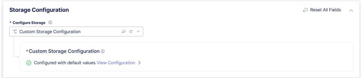
Figure: Configure Storage
-
From the
Storage Interfacesdrop-down menu, selectList of Storage Interface. -
Select
Configure, selectAdd Item, and then enter the following information:- Enter an
Interface Descriptionto help you identify the interface. - In the
Ethernet Interfacesection, enter the following information:- Select the
Ethernet Devicefield, selectSee Suggestions, and then select a device. - From the
Select Configuration for Cluster or Specific Nodedrop-down menu, specify if the new Ethernet interface applies toAll Nodes of the Site, or specify aSpecific Node. - Specify if the new interface is
Untaggedor selectVLAN IDand enter theID.
- Select the
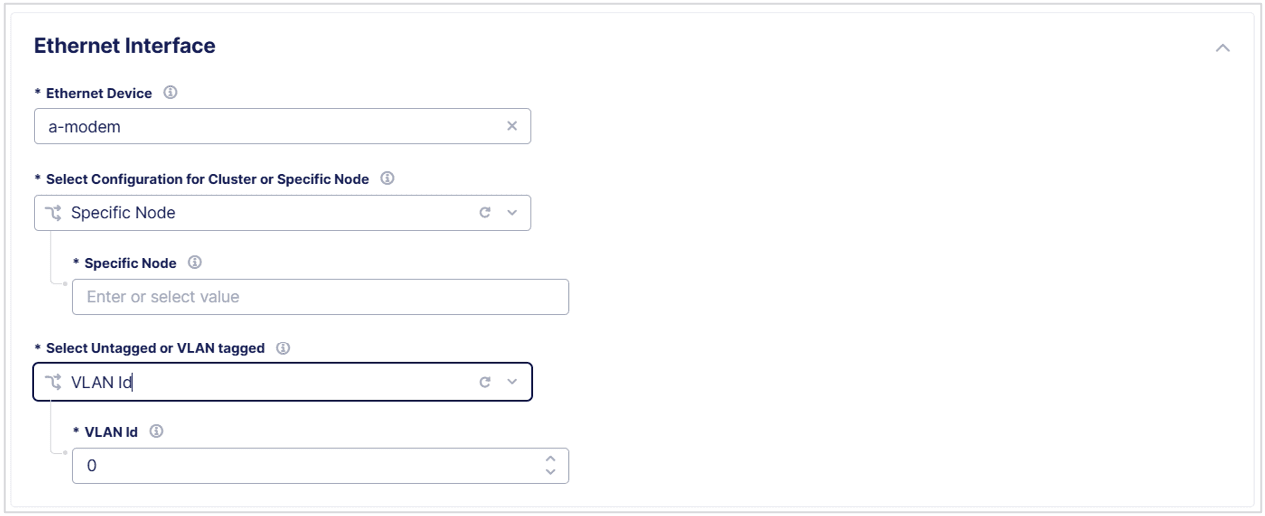
Figure: Configure a Storage Interface
- In the
IP Configurationsection, specify how the IP address is assigned to the new interface:DHCP Client: The Ethernet interface is assigned an IP address from an external DHCP server.DHCP Server: This is not a valid section for storage devices.Static IP: Enter theIP addressandPrefix Lengthof the new Ethernet interface and then enter the IP address of theDefault Gateway.
- In the
Virtual Networksection, enableShow Advanced Fields. - From the
Select Virtual Networkdrop-down menu, selectStorage Network. - In the
Common Configurationsection, from theSelect Primary Interfacedrop-down menu, selectInterface is Not Primary. - Select
Applyto save your settings. Then selectApplyagain.
- Enter an
-
From the
Storage Devicedrop-down menu, selectList of Storage Devices. Then selectAdd New.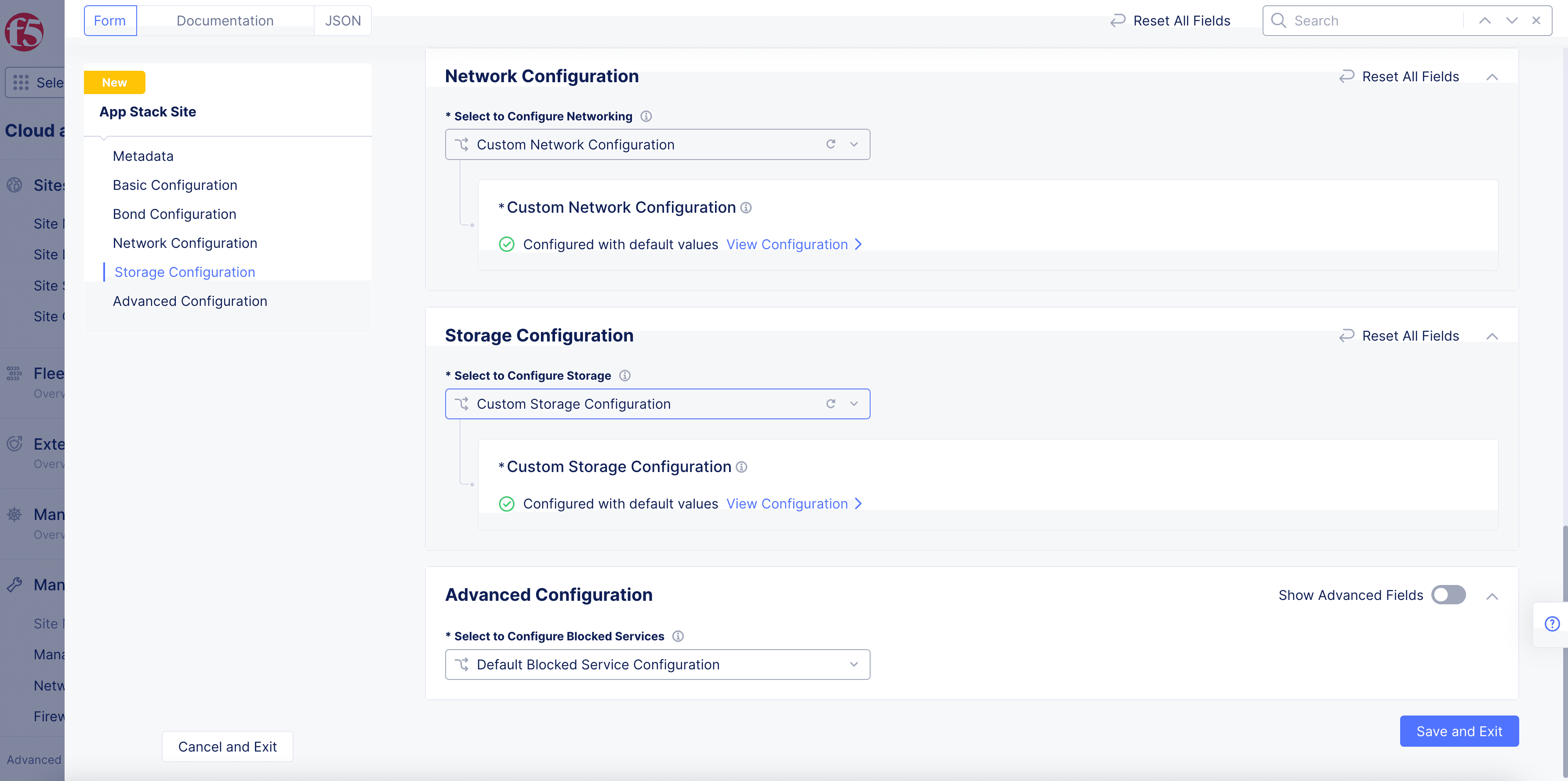
Figure: Configure a Storage Device
-
Enter a name in the
Storage Devicefield to identify the device. Ensure that this name corresponds to the class in which the storage device falls. The classes are used by vK8s for storage related actions. -
Select a storage device from the
Select Storage Device to Configuredrop-down menu. Then go to the corresponding device configuration instructions:-
HPE Storage
-
Custom Storage
Important: NetApp Trident and Pure Storage Service Orchestrator are not supported.
-

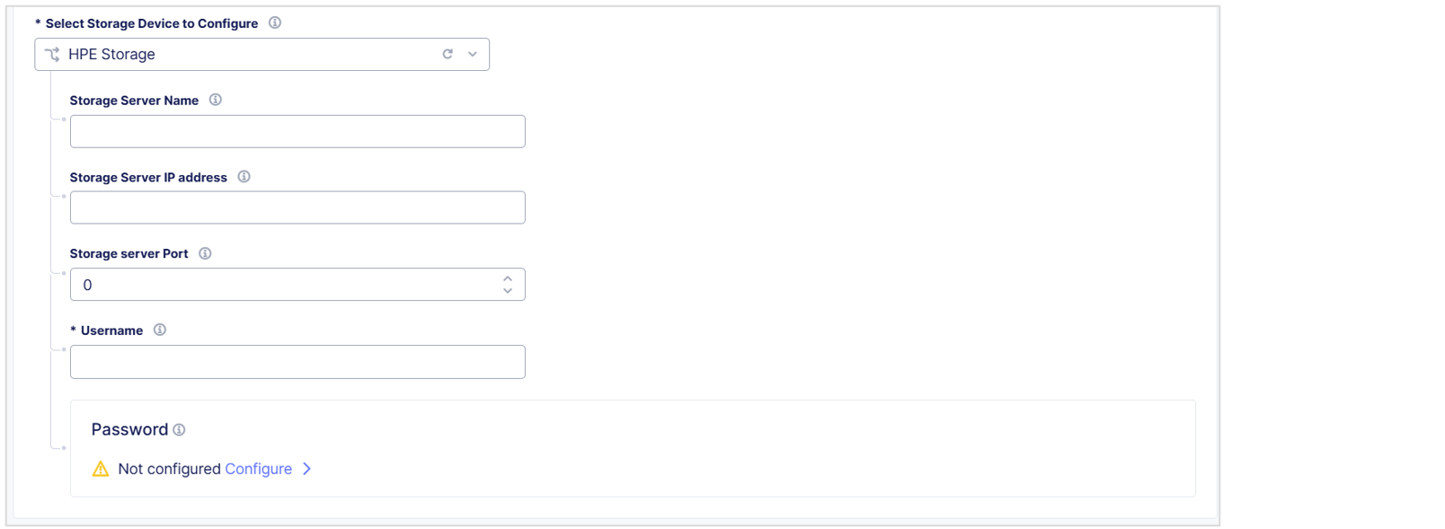
HPE Storage
-
From the
Select Storage Device to Configuredrop-down menu, selectHPE Storage. -
In the
Storage Server Namefield, enter a name to identify the server. -
In the
Storage Server IP addressfield, enter the IP address of the storage server. -
In the
Storage Server Portfield, enter the port number of the storage server. -
In the
Usernamefield, enter the username to connect to the HPE storage device.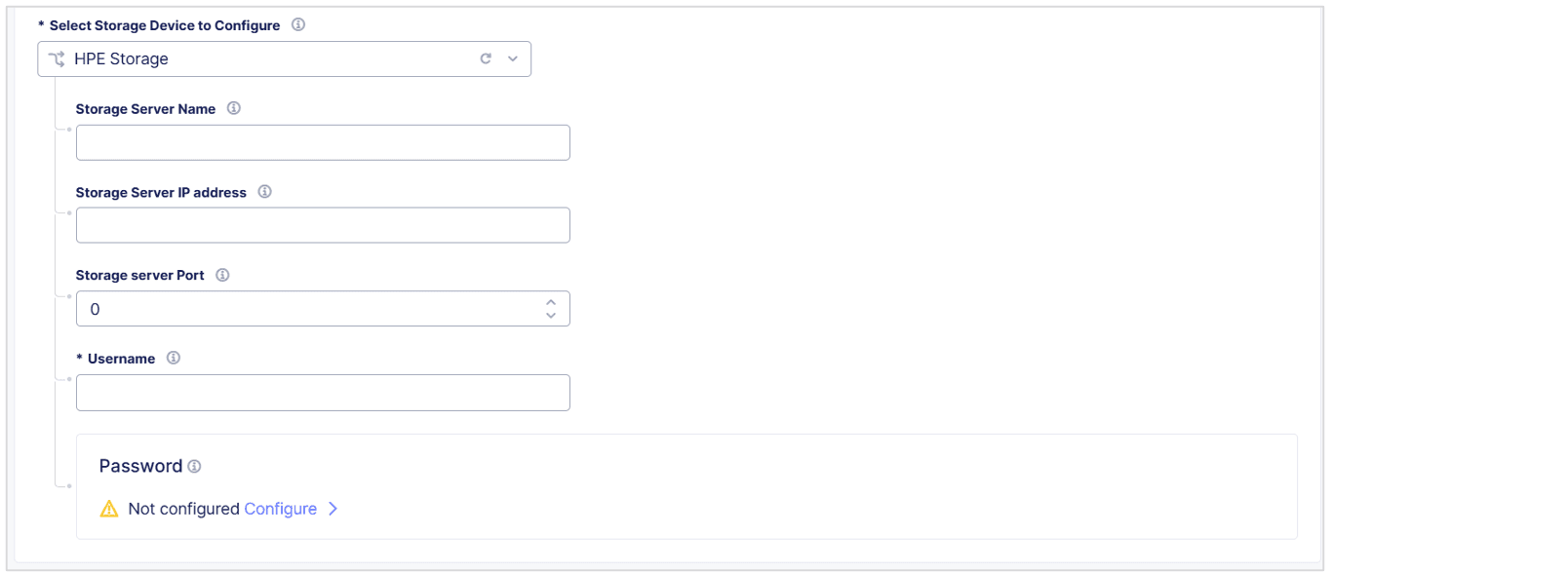
Figure: Configure an HPE Storage Device
-
In the
Passwordsection, enter the password to connect to the HPE storage device.- Select
Configureand then select one of the following options:Blindfold Secret: Enter the secret text to blindfold.Clear Secret: Enter the secret text in plaintext format or Base64. F5 strongly recommends that you use Base64 format.
- Select
Apply.
- Select
-
In the
Generic Parameterssection, enableShow Advanced Fields. -
Select
Add Itemand enter the storage classParameter NameandParameter Valuefor your HPE storage device.
Note: You can add multiple storage parameters.
- When you finish, select
Apply.
Next Steps
When you finish, see Configure Storage Classes.
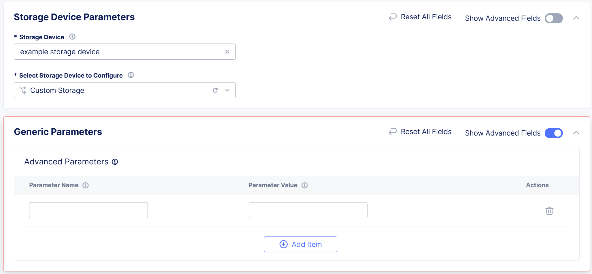
Custom Storage
Use the Custom Storage option for storage devices that you deploy outside of F5 Distributed Cloud Services. For example, use this option to configure custom storage classes for AWS, GCP, and so on.
-
From the
Select Storage Device to Configuredrop-down menu, selectCustom Storage. -
In the
Generic Parameterssection, enableShow Advanced Fields. -
Select
Add Itemand enter the storage classParameter NameandParameter Valuefor your storage device.Note: You can add multiple custom parameters.
-
When you finish, select
Apply.
Figure: Configure Custom Storage Device
Next Steps
When you finish, see Configure Storage Classes.
Configure Storage Classes
-
From the
Storage Classesdrop-down menu, selectAdd Custom Storage Class. -
Select
Add Itemand enter the following information:-
Storage Class Name: Enter the name of the storage class as it appears in Kubernetes. -
Storage Device: Enter the name of the storage device that you want this storage class to use. This name must be the same as the name for the storage device you configured previously. -
Default Storage Class: Select to make this storage class the default for the Kubernetes cluster. -
Select Storage Class Configuration: Select one of the following options:Important: NetApp Trident and Pure Storage Service Orchestrator are not supported.
HPE Storage:Secret Name: Enter the name of the secret to identify the backend storage authentication information.Secret Namespace: Enter the namespace where the backend storage information resides.destroyOnDelete: Specify if you want the backup Nimble volume (including snapshots) destroyed when the Kubernetes PVC is deleted.limitIops: Enter the limit for input/output operations per second for the storage class.limitMbps: Enter the limit of MB per second for the storage class.performancePolicy: Enter the name of the performance policy you want to assign to the volume.protectionTemplate: Enter the name of the protection template you want to assign to the volume.folder: Enter the name of the folder in which you want to place the volume.thick: Specify if the volume should be thick provisioned.dedupeEnabled: Specify if you want to enable deduplication.syncOnDetach: Specify if you want to sync the snapshot of the volume to the replication partner each time it is detached from the node.encrypted: Specify if you want the volume to be encrypted.pool: Enter the name of the pool in which you want to place the volume.allowOverrides: Specify parameters that you want to allow Kubernetes PVC to override.allowMutations: Specify parameters that you want to allow Kubernetes mutations to override.
Custom Storage: Enter the storage class YAML. It must have the following configuration.
Figure: Configure Storage YAML File
-
In the
Reclaim Policyfield, specify what happens to a persistent volume after its claim is released. Select eitherDeleteorRetain. -
To enable volume expansion for persistent volume claims, select the
Allow Volume Expansioncheckbox. -
In the
Generic Parameterssection, selectAdd Itemto add specific storage class parameter names and values. You can add multiple parameters.
-
-
Select
Apply. Then selectApplyagain.

Step 6: Perform advanced configuration.
- In the
Advanced Configurationsection, enable theShow Advanced Fieldsoption.
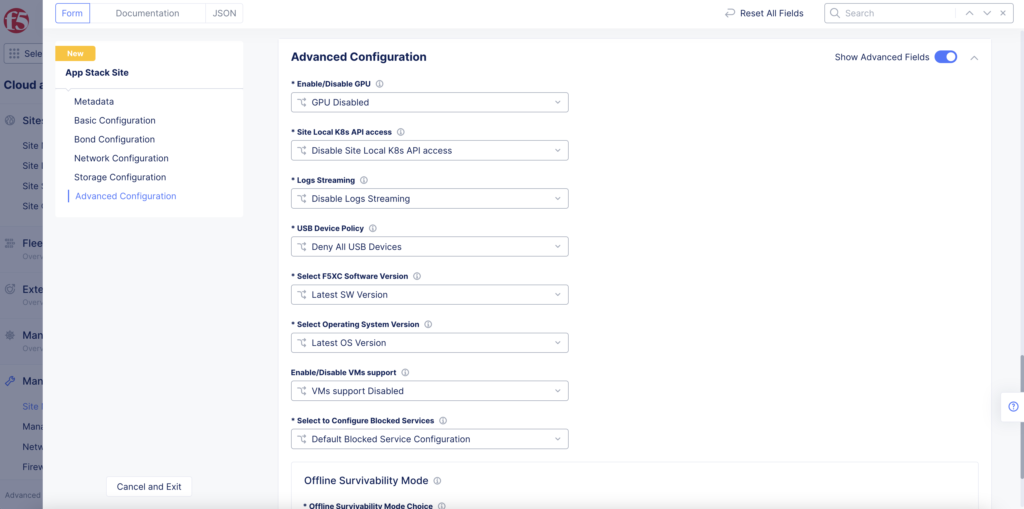
Figure: Advanced Configuration
-
Optionally, select
GPU EnabledorvGPU Enabledfrom theEnable/Disable GPUmenu. This enables GPU capability for the site hardware. -
Optionally, configure managed K8s for your site per the following guidelines:
-
Select
Enable Site Local K8s API accessfrom theSite Local K8s API accessmenu. -
Click on the
Enable Site Local K8s API accessfield and select a K8s cluster object from the list. You can also selectCreate new k8s Clusterto create and apply the K8s cluster object.
-
-
Optionally, enable logs streaming and either select a log receiver or create a new log receiver.
-
Optionally, select a USB device policy. You can deny all USB devices, allow all USB devices, or allow specific USB devices.
-
Optionally, specify a Distributed Cloud Services software version. The default is the
Latest SW Version. -
Optionally, specify an operating system version. The default is the
Latest OS Version.
Note: The advanced configuration also includes managed K8s configuration. This is an important step if you want to enable managed K8s access. This is possible only at the time of creating the App Stack site and cannot be enabled later by updating the App Stack site.
-
To enable SR-IOV for your site:
-
From the
SR-IOV interfacesmenu, selectCustom SR-IOV interfaces Configuration. -
Click
Add Item.
-
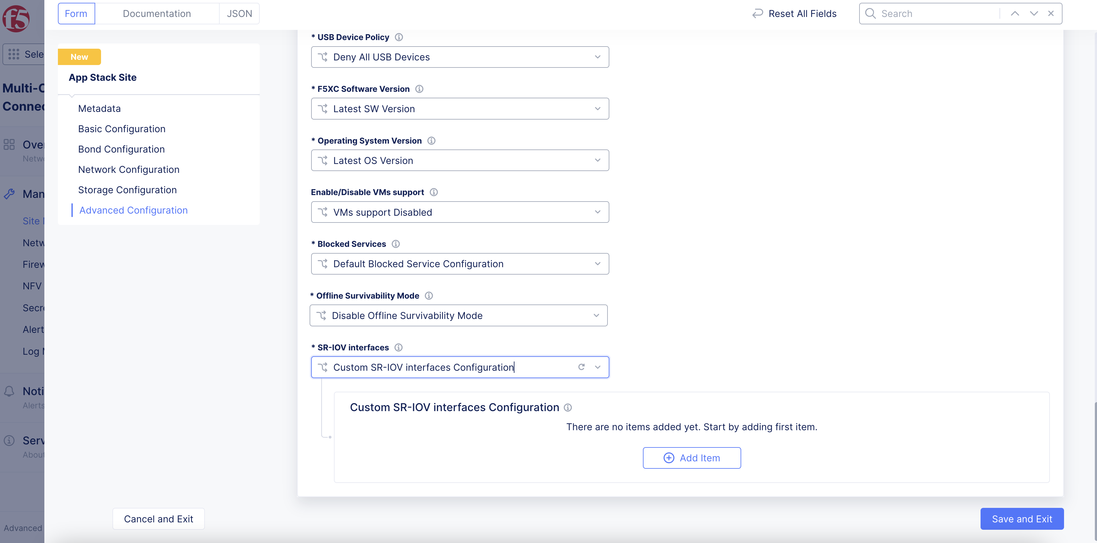
Figure: Enable Custom SR-IOV Interface
-
In the
Name of physical interfacefield, enter a name for the physical adapter that will use a virtual function (VF). -
In the
Number of virtual functionsfield, enter the number of VFs used for the physical interface. -
If you are using SR-IOV with either a virtual machine (VNF) or a Data Plane Development Kit (DPDK) application in a pod (CNF): In the
Number of virtual functions reserved for vfiofield, enter the number of virtual functions reserved for use with VNFs and DPDK-based CNFs. VNF (VM) needs to usevfioeven if it is not running a DPDK application. The number of VFs reserved forvfiocannot be more than the total number of VFs configured.
Note: If you use SR-IOV with a virtual machine or DPDK-based pod, the network name in the VM/pod manifest file should have
-vfioappended to the network name (subnet).
- Click
Applyto set the SR-IOV interface configuration.
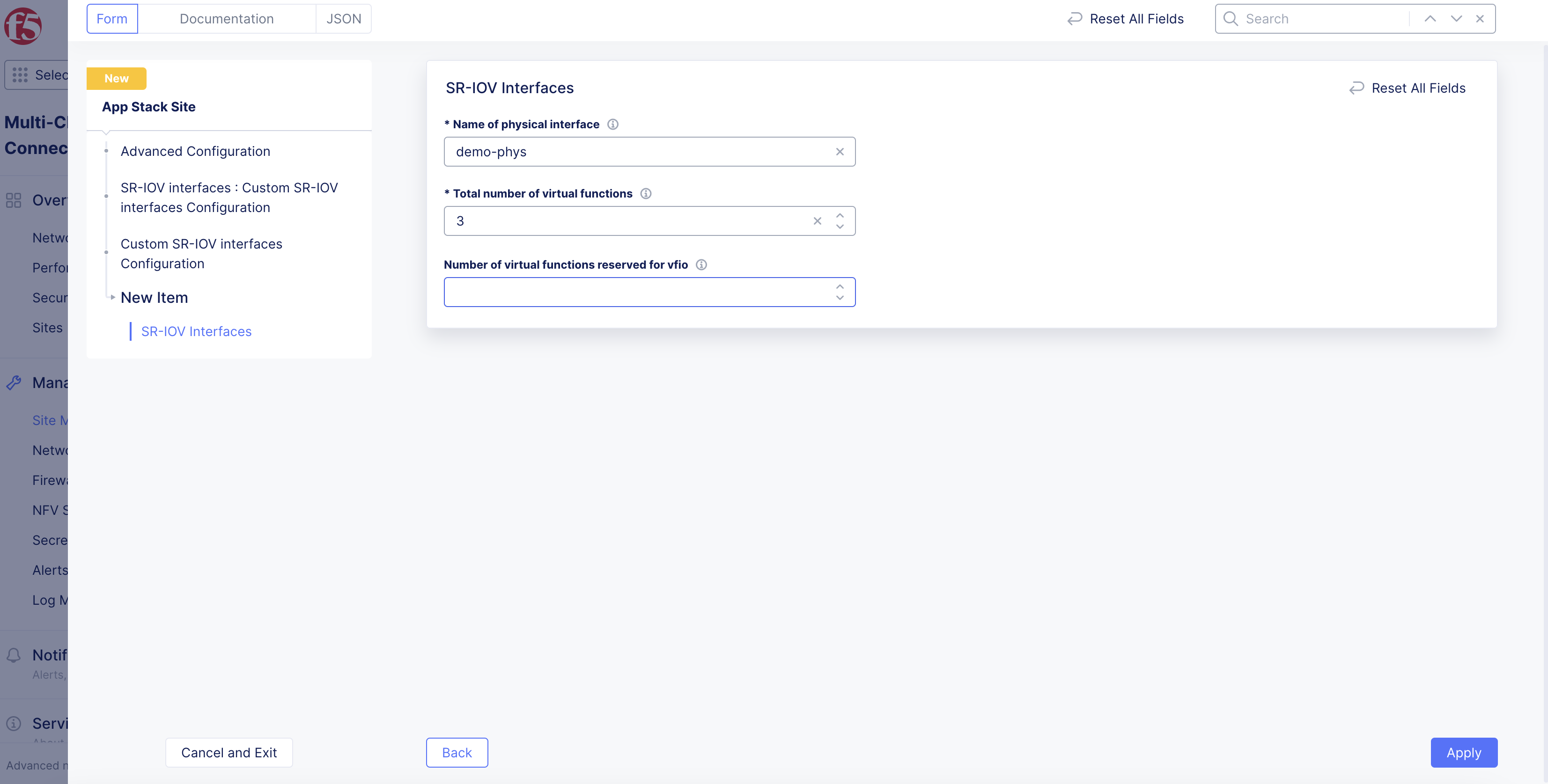
Figure: Set Number of Virtual Functions
Note: After you enable this SR-IOV interface configuration option, your site reboots if it is an existing site, provisioning new VFs. For new sites, the provisioning process occurs during initial site deployment. It may take several minutes for an existing site to reboot after enabling this feature.
Step 7: Complete creating the App Stack site.
Select Save and Exit to complete creating the App Stack site.
Note: You can also configure multiple interfaces for Virtual Machines (VM) or containers running in a K8s cluster within an App Stack Site. For instructions, see Create Workloads with Multiple Network Interfaces.
Perform Site Registration
After creating the App Stack site object in Console, the site shows up in Console with Waiting for Registration status. Install the nodes and ensure that the cluster name and host name for your nodes match with the App Stack site name and node name per the Basic Configuration section of App Stack site you configured.
Perform registration per the following instructions:
-
Navigate to
Manage>Site Management>Registrations. -
Choose your site from the list of sites displayed under the
Pending Registrationstab. -
Approve the option (blue checkmark).
-
Ensure that the cluster name and hostname is matching with those of the App Stack site.
-
Select
Acceptto complete registration and the site turns online.
Concepts
- System Overview
- Core Concepts
- Networking
- F5 Distributed Cloud - Customer Edge
- F5 Distributed Cloud Site