Create Multi-Node KVM Site on Equinix
Objective
Important: This is a legacy workflow for deploying Customer Edge (CE) Sites and is not recommended to use. A new workflow for deploying Customer Edge (CE) Sites has been introduced and is now Generally Available (GA). It is recommended to use the new Secure Mesh Site (v2) workflow for all Customer Edge deployments. You can find this workflow here.
This document provides instructions on how to deploy and configure an F5® Distributed Cloud Services multi-node Kernel-based Virtual Machine (KVM) site on Equinix Metal service. To learn more about sites, see F5 Distributed Cloud Site.
Using the instructions provided in this document, you can deploy three Equinix bare metal servers with CentOS as the host operating system, create virtual machines on them, install F5 Distributed Cloud Services software on those virtual machines (VMs), and then register the nodes into a multi-node cluster site.
Prerequisites
-
A Distributed Cloud Services account. If you do not have an account, see Getting Started with Console.
-
An Equinix Bare Metal Account. For more information, see Equinix Documentation.
-
Resources required per node: Minimum 4 vCPUs, 14 GB RAM, and 80 GB disk storage. For a full listing of the resources required, see the Customer Edge Site Sizing Reference guide. All the nodes in a given CE Site should have the same resources regarding the compute, memory, and disk storage. When deploying in cloud environments, these nodes should use the same instance flavor.
-
Allow traffic from and to the Distributed Cloud public IP addresses to your network and allowlist related domain names. See Firewall and Proxy Server Allowlist Reference guide for the list of IP addresses and domain names.
-
Internet Control Message Protocol (ICMP) needs to be opened between the CE nodes on the Site Local Outside (SLO) interfaces. This is needed to ensure intra-cluster communication checks.
Important: After you deploy the CE Site, the IP address for the SLO interface cannot be changed. Also, the MAC address cannot be changed.
Configuration
In case of this deployment, the F5® Distributed Cloud Mesh (Mesh) nodes require two interfaces attached. The first interface is the outside interface through which services running on the node can connect to the Internet. The second interface is the inside interface whose IP address is the default gateway IP address for all the application workloads and services present in the private subnets.
This image provides a high-level view of the network topology:

Figure: Equinix Deployment Topology
Deploy Equinix Metal Servers
In case of deploying Mesh nodes on Equinix, first deploy three on-demand Equinix bare metal servers.
Note: Equinix Metal supports various types of server instance sizes and different CPU architectures. However, you can only deploy Mesh on x86 CPU architecture and not on Atom or ARM architectures.
Also, the following Equinix Metal instance sizes do not support the Layer 2 functionality required for a successful deployment:
- t1.small.x86
- c1.small.x86
- X1.small.x86
Perform the following steps:
Step 1: Start creating Equinix Metal Servers.
-
Log into the Equinix Console with your account credentials.
-
Click
Servers>Choose Deploy Type>Deploy On Demand Servers.

Figure: Equinix Metal Location and Deploy Type
- Select a location and a server type.
Step 2: Set operating system and the number of servers.
-
Select
CentOSand chooseCentOS 7as the operating system version. -
Use the
+button to set three servers and enter names for each of them.

Figure: Operating System and Server Names
Step 3: Optionally, add the user data and start deploying the servers.
- Prepare the user data for configuring packages. The following is a sample:
#cloud-config

package_upgrade: true

packages:
    - qemu-kvm
    - qemu-img
    - virt-manager
    - libvirt
    - libvirt-python
    - libvirt-client
    - virt-install
    - virt-viewer
    - bridge-utils

runcmd:
   - systemctl start libvirtd
   - virsh net-undefine default
   - virsh net-destroy default
-
Enable the
Add User Dataoption and paste the configuration you prepared. -
Click the
Deploy Nowbutton to start deploying the servers.

Figure: Add User Data and Deploy Servers
Step 4: Verify that the servers are deployed.
After successful deployment, the Servers page displays the list of metal servers deployed.

Figure: Deployed Servers
Step 5: Request elastic IP block.
After creating the servers, you are required to configure IP addresses by obtaining an elastic IP address block.
- Click
IPs & Networks>IPs.

Figure: IPs & Networks Configuration
-
Select
Public IPv4, choose a location, choose a quantity, and then clickSubmit Request. -
Repeat for the
Public IPv6option.

Figure: Request Public IPv4 Block
- Verify the IP addresses are assigned in the
PROJECT IP ADDRESSEStab.
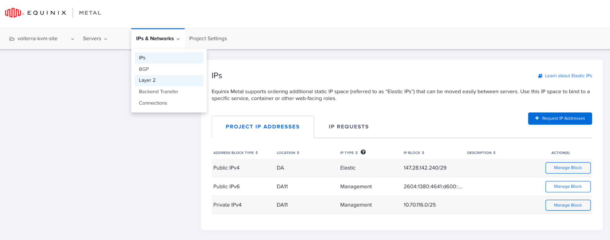
Figure: Verify the IP Address Blocks
Step 6: Create virtual local area network (VLAN).
The dual network interface controller (NIC) Mesh installation requires two VLANs: one for the internal interface and one for the external interface.
-
Click
IPs & Networks>Layer 2. -
Click
Add New VLAN. -
Set the description to indicate it is an internal VLAN and click
Add.

Figure: Add Internal VLAN
-
Repeat the previous step to create another VLAN and set the description to indicate that it is an external VLAN.
-
Verify the created VLANs.

Figure: Created VLANs
Convert Server Networking and Assign IPs/VLANs
When an Equinix Metal server is first deployed, there is a single-bonded interface. To support the dual-NIC Mesh installation, the server networking type needs to be converted to Hybrid Bonded. By converting to hybrid bonded, the VLANs created in the previous section can be assigned to the bare metal instance.
Step 1: Convert networking to hybrid bonded mode.
- Go to the
Serverspage and click on a server for which the networking is required to be converted.

Figure: Equinix Server List
The server overview page displays the networking information:

Figure: Server Overview
-
Select
Networkfrom the left menu to open the network page. -
Click
Convert to Other Network Type.

Figure: Convert Network Type
-
Select
Hybridin the network type selection window. -
Select
Bondedin the options and select one of the VLANs to assign.

Figure: Conversion to Hybrid Bonded with VLAN
Note: You can select any of the created VLANs. The second VLAN will be assigned in the next step. Therefore, the order of configuration does not matter.
- Click
ASSIGN NEW VLAN & CONVERT TO HYBRID NETWORKING.
Step 2: Assign second VLAN to the bare metal instance.
- In the
Networkpage, go to theLayer 2section and clickAdd New Vlan.
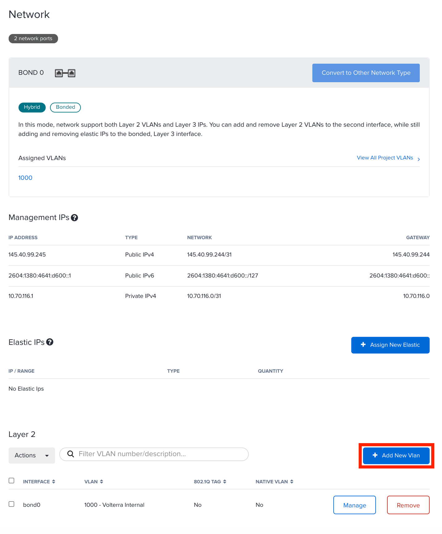
Figure: Add New VLAN
- In the
Add New Vlanwindow, select the other VLAN in theNetworkfield and clickAdd.
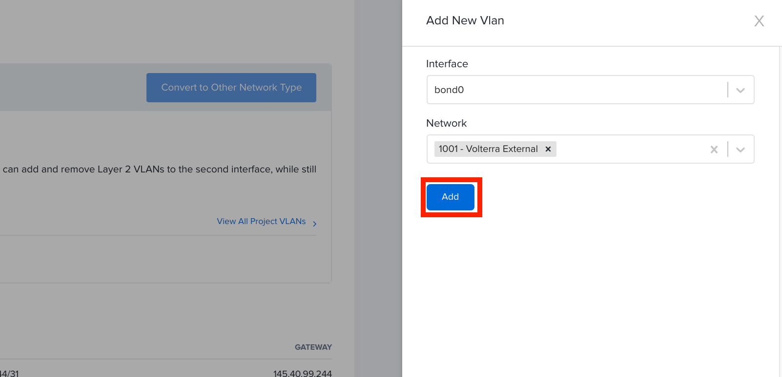
Figure: Add Second VLAN
Step 3: Add elastic IP addresses to the bare metal instances.
Each metal instance requires two elastic IP addresses, one IP address for the network bridge interface and another for the Mesh external interface. To use an elastic IP address, it must be assigned to the metal instance.
After planning your address scheme, perform the following:
- From the Elastic IP block that was allocated in the previous section, assign two
/32addresses.
In this example, the allocated IP block is 147.28.142.240/29 and the first or last IP addresses are not used, as they represent the network and broadcast addresses.
The following table shows the sample IP addresses this example sets:
| Metal Instance | Bridge IP Address | Distributed Cloud Services External IP Address |
|---|---|---|
| VoltMesh-01 | 147.28.142.241 | 147.28.142.242 |
| VoltMesh-02 | 147.28.142.243 | 147.28.142.244 |
| VoltMesh-03 | 147.28.142.245 | 147.28.142.246 |
-
In the
Networkpage for your server, clickAssign New Elasticin theElastic IPssection. -
In the
Add Elastic IPwindow, selectPublic IPv4from theAddress Typemenu. -
Select an option from the
Blockmenu. -
Select
/32from theLengthmenu. -
Select an address from the
Address/Rangemenu. -
Click
Add.

Figure: Add Elastic IP Address

Figure: Elastic IP Addresses Added
-
Repeat the above steps to add another IP address.
-
From the
SERVER ACTIONSmenu, selectREBOOTto reboot and apply the changes.

Figure: Reboot the Instance
- Repeat the steps above for all your bare metal instances.
Deploy Site on Equinix Metal Servers
Deploying a multi-node site includes installing Mesh node on each of the metal servers. This involves configuring KVM on the instances, creating VMs with Mesh node images, performing post-installation configuration, and registering the Mesh nodes.
Configure the KVM hypervisor to support installation of Mesh software. Repeat this process for each bare metal instance.
Step 1: Connect to your instances using SSH.
- To SSH into the first metal instance, click
...>SSH Info.
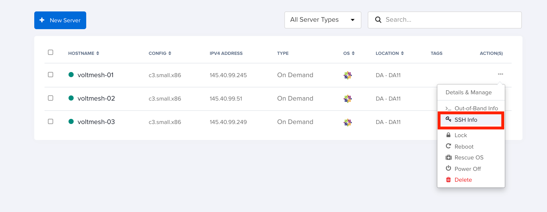
Figure: Obtain SSH Information
- Click
Copyto copy the SSH command displayed on the screen.

Figure: Copy SSH Command
- Using your preferred SSH client, log into the server as root.
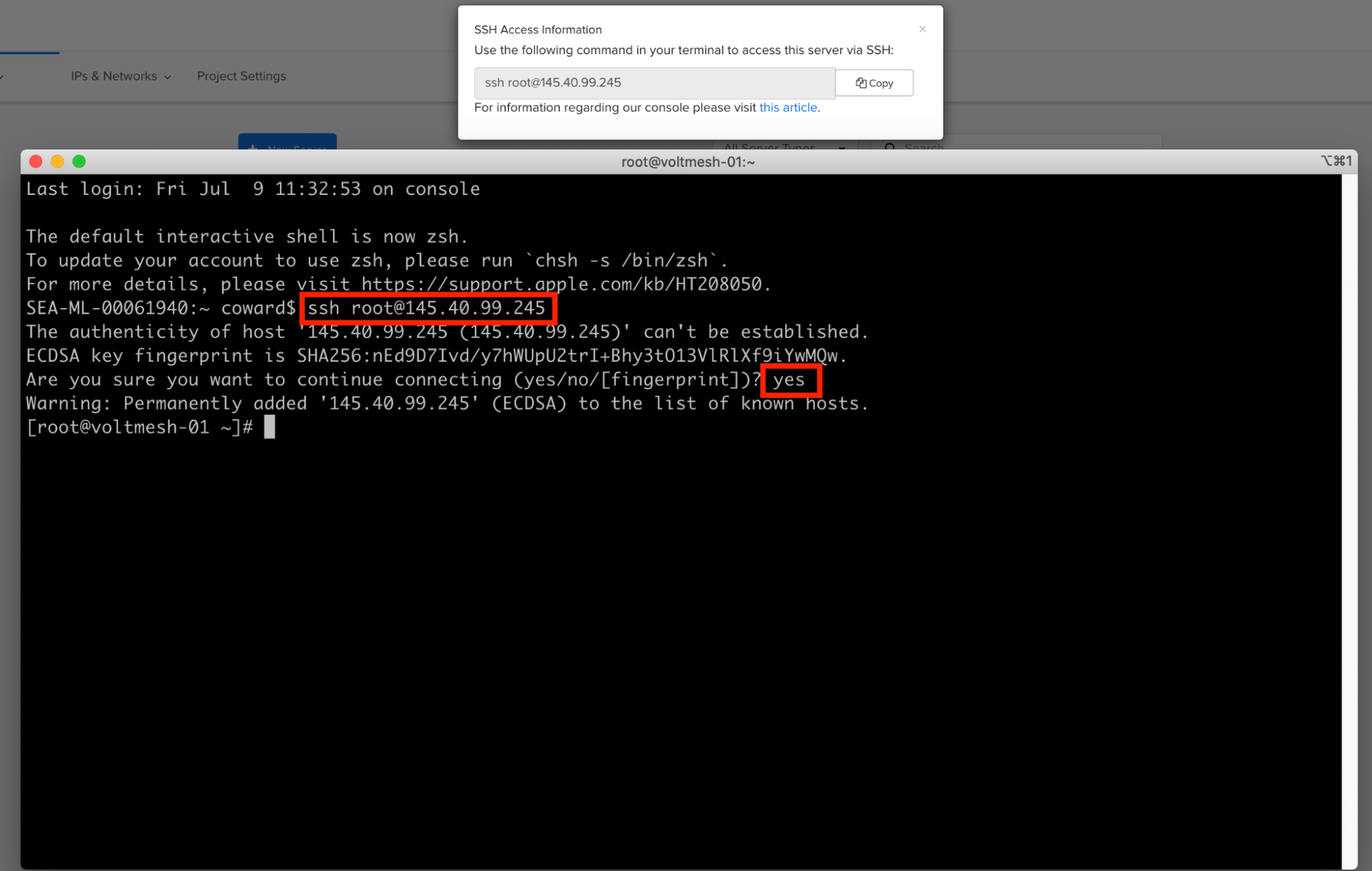
Figure: Connect to Instance Using SSH
Step 2: Edit system configuration to support Mesh cluster operation.
- Open the
sysctl.conffile for editing:
vi /etc/sysctl.conf
- Add the following contents to the end of the file and save the changes:
vm.nr_hugepages = 1200
net.ipv4.ip_forward = 1
net.bridge.bridge-nf-call-ip6tables = 0
net.bridge.bridge-nf-call-iptables = 0
net.bridge.bridge-nf-call-arptables = 0
- Load the bridge filter module:
modprobe br_netfilter
- Apply the changes:
sysctl -p
Step 3: Download Mesh KVM software.
- Copy the link to the latest software from the KVM Images page and use the
wgetcommand to download the image. The following is a sample command:
wget -O /var/lib/libvirt/images/volterra.iso https://vesio.blob.core.windows.net/dev/images/centos/7.2009.10-202106210938/vsb-ves-ce-certifiedhw-generic-production-centos-7.2009.10-202106210938.1624275431.iso
- Wait for the download to complete. The download progress is indicated, and after completion, the command prompt is returned.
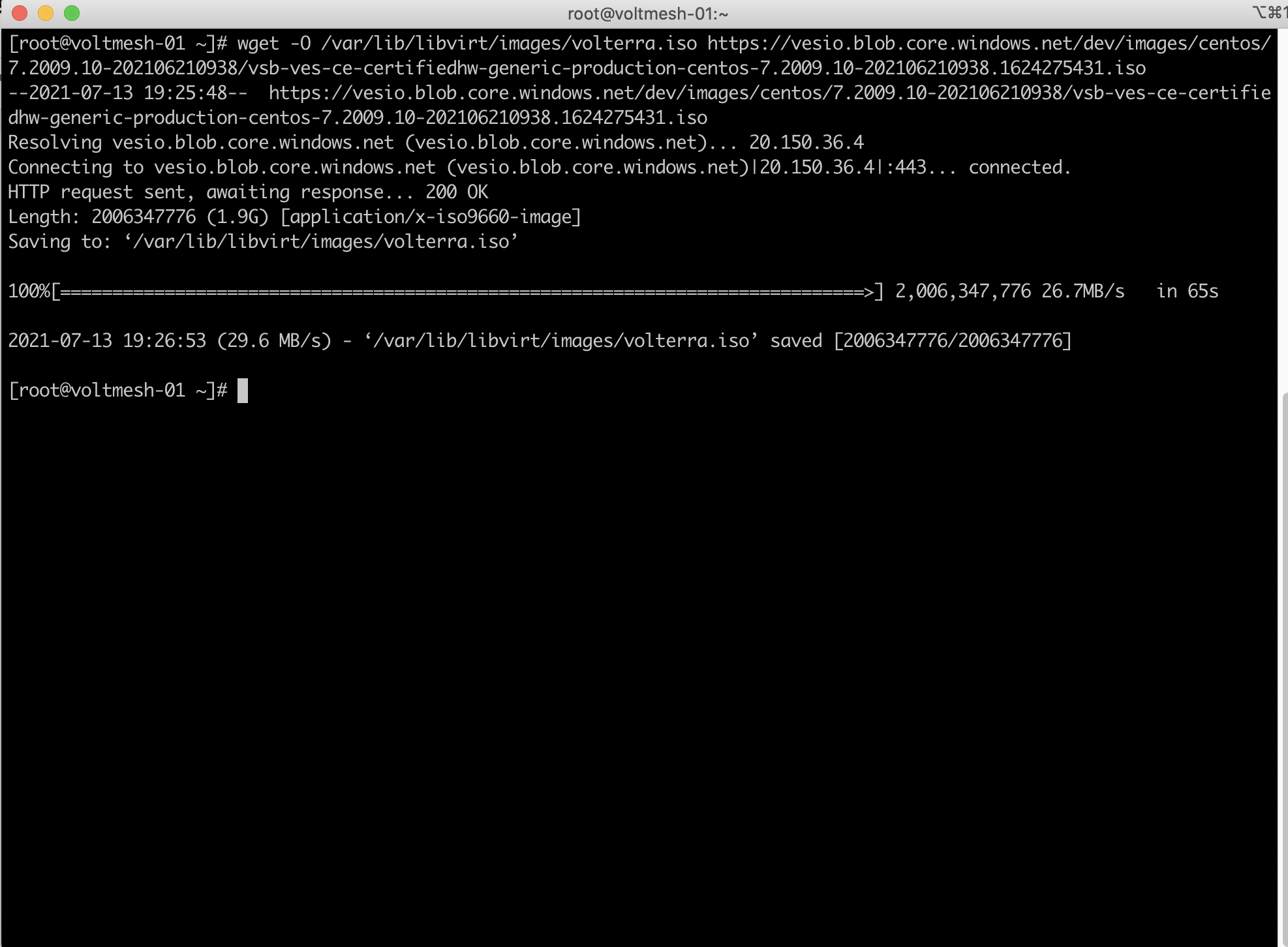
Figure: Download of Mesh KVM Software
Step 4: Create a disk image for the Mesh node.
Enter the following command:
qemu-img create /var/lib/libvirt/images/disk1.qcow2 30G
Step 5: Define KVM internal and external network interfaces.
Define the internal and external KVM network interfaces and apply configuration parameters. The format of the device name is bond0.<VLAN ID>. In this example, the VLAN IDs assigned to the Distributed Cloud Services internal and external VLANs are 1000 and 1001, respectively.
- Create the internal VLAN interface file for editing:
vi /etc/sysconfig/network-scripts/ifcfg-bond0.1000
- Add the following values and save the file:
DEVICE=bond0.1000
ONBOOT=yes
BOOTPROTO=none
BRIDGE=br0
VLAN=yes
- Create the external VLAN interface:
vi /etc/sysconfig/network-scripts/ifcfg-bond0.1001
- Add the following values and save the file:
DEVICE=bond0.1001
ONBOOT=yes
BOOTPROTO=none
BRIDGE=br1
VLAN=yes
Step 6: Configure internal VLAN interface network bridge IP addresses.
Define the Distributed Cloud Services internal VLAN interface network bridge IP addresses. The external Distributed Cloud Services interface uses public IP addresses. For internal interface, the RFC1918 private addresses are used. This step configures only the bridge IP address for each instance.
Note: The internal IP address configuration is performed within F5® Distributed Cloud Console (Console) during a later step.
You can choose an IP address scheme per your choice for internal addressing, except the IP address space used by the bond0:0 interface. You can find the IP used by the bond0:0 interface by running the ip addr command.
In this example, the 192.168.100.0/24 address block is used. The following is the allocation scheme for this example:
| Metal Instance | Bridge IP Address | Distributed Cloud Services Internal IP Address |
|---|---|---|
| VoltMesh-01 | 192.168.100.10 | 192.168.100.11 |
| VoltMesh-02 | 192.168.100.20 | 192.168.100.21 |
| VoltMesh-03 | 192.168.100.30 | 192.168.100.31 |
Note: Bridge IP Address is the
SiteLocalInsidegateway and Distributed Cloud Services internal IP address is theSiteLocalInsideIP prefix within Console.
- Create and open the internal bridge interface file for editing:
vi /etc/sysconfig/network-scripts/ifcfg-br0
- Add
DNS1,DNS2,IPADDR, andPREFIXsettings and save the file. The following is a sample for the first metal instance:
DEVICE=br0
STP=no
TYPE=Bridge
BOOTPROTO=none
DEFROUTE=yes
NAME=br0
ONBOOT=yes
DNS1=8.8.8.8
DNS2=8.8.4.4
IPADDR=192.168.100.10
PREFIX=24
- Repeat the steps for each metal instance with the appropriate IP address based on your address scheme.
Step 7: Configure external VLAN interface network bridge IP addresses.
Define the Distributed Cloud Services external VLAN network bridge IP addresses. We recommend you use the IP address pattern as shown in the example below. Make sure not to use the first and last IP addresses in the /29 address range.
This example uses the elastic IP block 147.28.142.240/29.
Note: This step configures only the bridge IP address for each instance. External IP address configuration is performed within Console during a later step.
The following is the scheme used for this example:
| Metal Instance | Bridge IP Address | Distributed Cloud Services External IP Address |
|---|---|---|
| VoltMesh-01 | 147.28.142.241 | 147.28.142.242 |
| VoltMesh-02 | 147.28.142.243 | 147.28.142.244 |
| VoltMesh-03 | 147.28.142.245 | 147.28.142.246 |
Note: Use the Elastic IP addresses from the block obtained in the Deploy Equinix Metal Servers chapter. The Bridge IP address is
SiteLocal GWand the Distributed Cloud Services external IP address is theSiteLocal IP prefixwithin Console.
- Create and open the internal bridge interface file for editing:
vi /etc/sysconfig/network-scripts/ifcfg-br1
- Add
DNS1,DNS2,IPADDR, andPREFIXsettings and save the file. The following is a sample for the first bare metal instance:
DEVICE=br1
STP=no
TYPE=Bridge
BOOTPROTO=none
DEFROUTE=yes
NAME=br1
ONBOOT=yes
DNS1=8.8.8.8
DNS2=8.8.4.4
IPADDR=147.28.142.241
PREFIX=29
-
Repeat the steps for each metal instance with the appropriate IP address based on your address scheme.
-
Reboot the metal instances and ping the elastic IP addresses to verify connectivity.
Create and Configure Mesh Virtual Machines
Create a Mesh virtual machine (VM), assign IP addresses to the internal and external interfaces, and configure the Mesh settings.
Step 1: Create Mesh VM using the KVM CLI.
- Enter the following command:
virt-install --name volterra \
--ram 16384 --vcpus=8 \
--os-variant=centos7.0 \
--network bridge=br1,model=virtio \
--network bridge=br0,model=virtio \
--accelerate \
--disk path=/var/lib/libvirt/images/disk1.qcow2,bus=virtio,cache=none,size=64 \
--cdrom /var/lib/libvirt/images/volterra.iso \
--noautoconsole --noreboot
- To start the VM, enter the following command:
virsh start volterra
- To start the VM automatically when the underlying host OS is started, enter the following command:
virsh autostart volterra
-
After the VM is started, use the KVM console to connect to it. The ID of the VM assigned by the KVM is required for this.
-
To obtain the ID assigned to the VM, enter the following command:
virsh list

Figure: Obtain the Virtual Machine ID
Step 2: Connect to the local Console.
- Connect to the local console of the VM using the VM ID obtained in the previous step. The following is a sample command:
virsh console 1
- At the login prompt, use
adminas the username andVolterra123as the password.

Figure: Local Console
- After logging in for the first time, choose a new password. Passwords must be at least eight (8) characters long and include at least one upper-case letter.
Step 3: Configure Mesh external interface.
-
Use the tab key to open the configuration menu and navigate to
configure-network, and then press the enter key to start network configuration. -
Use the arrow keys to navigate to the
OUTSIDEoption and press the space bar to select.

Figure: Select Outside Network Interface
- On the screen that follows, populate the fields as shown in the following image:

Figure: Configure Outside Interface
- To confirm the changes, enter
yand then press the enter key.
Step 4: Configure Mesh internal interface.
-
Use the tab key to open the configuration menu and navigate to
configure-networkand press enter key to start network configuration. -
Use the arrow keys to navigate to the
INSIDEoption and press the space bar to select.

Figure: Select Inside Network Interface
- On the screen that follows, populate the fields as shown in the following image:

Figure: Configure Inside Interface
-
Ensure that you set the primary interface as
OUTSIDE. -
To confirm the changes, enter
yand then press the enter key.
Step 5: Create or obtain a site token.
To configure Mesh and register your site, a site token is required. You can create a new token or use an existing token. This example shows steps to create a new token.
-
Log into Console.
-
Click
Multi-Cloud Network Connect.
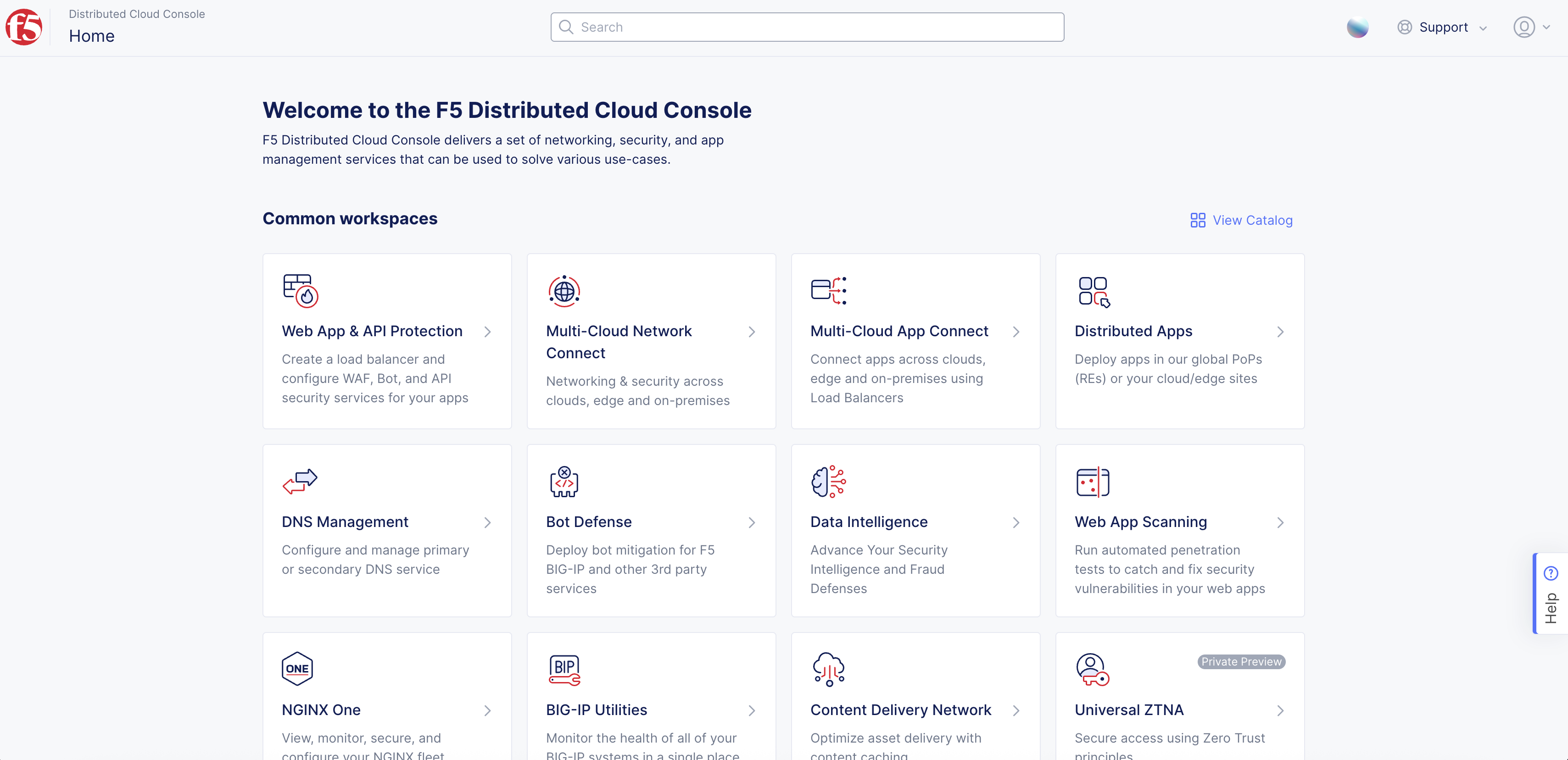
Figure: Console Homepage
-
Click
Manage>Site Management>Site Tokens. -
Click
Add site token. -
Enter a name for the token and click
Add site token. -
Note down the generated token code under the
UIDcolumn for your token.
Step 6: Configure other required Mesh settings.
At this point, you can either connect using the KVM console or use SSH to connect. In case of SSH, you can use the elastic IP address you configured in the previous section. This example shows connecting using SSH.
- Connect to the Mesh node using SSH and the elastic IP address for your instance.
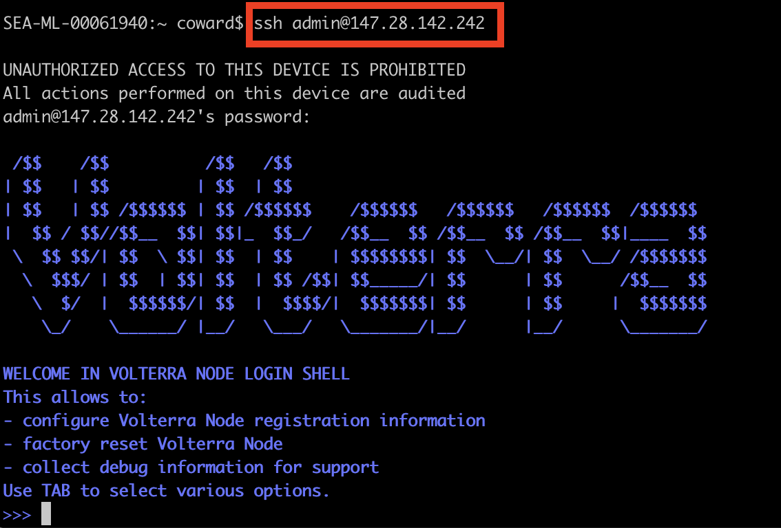
Figure: Connect Using SSH
-
Use the tab key to open the configuration menu and navigate to
configureand press the enter key to begin configuration. -
On the screen that follows, populate the fields as shown in the following image:

Figure: Mesh Node Configuration
-
For
What is your tokenandWhat is your site name?, enter the same name and token for all nodes. Use the token created in the previous step. -
To confirm the changes, enter
yand then press the enter key. Your node will start to connect to Console for registration.
Step 7: Register your site.
-
Click
Manage>Site Management>Registrations. -
Choose your site from the list of sites displayed under the
Pending Registrationstab. -
Click the blue checkmark.
-
On the page that opens, set the
Cluster Sizeto3. Make sure that you set each node to the same cluster size. -
Click
Save and Exitto complete the registration process. -
Repeat the above steps for each of the remaining nodes.
Note: It may take a few minutes for the registration process to complete and the site to change to
ONLINE.
Concepts
- System Overview
- Core Concepts
- Networking
- F5 Distributed Cloud - Customer Edge
- F5 Distributed Cloud Site