Create Azure Site (Orchestrated)
Objective
Important: F5 highly recommends you use the new Secure Mesh Site (v2) workflow for AWS, Azure, and GCP using this guide. This workflow is only recommended when you want F5 Distributed Cloud Services to orchestrate cloud resources needed for Customer Edge (CE) Site deployments in public clouds.
This guide provides instructions on how to create a site using F5® Distributed Cloud Console (Console) and deploy to Azure Virtual Network (VNet).
You can deploy an F5® Distributed Cloud Services Site to VNet using one of the following methods:
Using the instructions provided in this guide, you can deploy an ingress gateway site or ingress/egress gateway site.
Azure VNet Site Design Overview
The Azure VNet Site automates the deployment of sites in Azure. As part of the Azure VNet Site configuration, you can indicate that new VNet, subnets, and route tables need to be created. You also can choose to provide an existing VNet. The subnet information, creation of the VNet, and subnet resources will be skipped.
Note: By default, a Site deployed in Azure supports Azure Disk Storage. You can configure storage within the Site creation form or using a Fleet. This document provides steps to configure storage using the Site configuration form. See the Create Fleet guide for more information on using the Fleet method.
Deployment Environments
F5® Distributed Cloud Services supports Azure VNet site creation in both greenfield and brownfield environments. In a greenfield environment, Distributed Cloud Services can automate the creation of VNet networks, subnets, firewall rules, routes, and other networking features. In a brownfield environment, you can choose existing resources from your VNet or choose to create new resources using the site creation wizard.
Customer Edge Node Clustering
Azure VNet sites can be deployed as a single node or as a three-node site. These nodes host the control processes, data plane processes, and the IPsec connections to the Regional Edges (REs). For production deployments, F5 recommends a three-node site as it provides high availability and capacity for L7 features, like load balancing, WAAP, and more.
Azure VNet Site Deployment Modes
A site can be deployed in two different modes with the Azure VNet site workflow.
-
Ingress Gateway (One Interface): In this deployment mode, the site is attached to a single VNet and single Subnet. It can provide discovery of services and endpoints reachable from this subnet to any other site configured in the Distributed Cloud Services tenant.
-
Ingress/Egress Gateway (Two Interfaces): In this deployment mode, the site is attached to a single VNet with at least two interfaces on different subnets. In this mode, the site provides security and connectivity needs for virtual machines and subnets via a default gateway through the Site Inside interface. One subnet is labeled
Outsideand the other is labeledInside. This VNet can be configured in one of these two modes: Standalone VNet or Hub VNet.
Ingress Gateway (One Interface)
In this deployment mode, F5® Distributed Cloud Mesh (Mesh) needs one interface attached. Services running on the node connect to the Internet using this interface. Also, this interface is used to discover other services and virtual machines and expose them to other sites in the same tenant. For example, in the below figure, TCP or HTTP services on the DevOps or Dev Azure VM instances can be discovered and exposed via reverse proxy remotely.
As shown in the below figure, the interface is on the Outside subnet which is associated with the VNet main routing table, whose default route is pointing to the Internet gateway. That is how traffic coming from the outside interface can reach the Internet, along with other subnets associated with this routing-table object. In case of other subnets (for example, Dev and DevOps), these are associated with the VNet main routing table, which means that any newly created subnet in this VNet is automatically associated with this routing table.
A three-node deployment diagram is shown below.
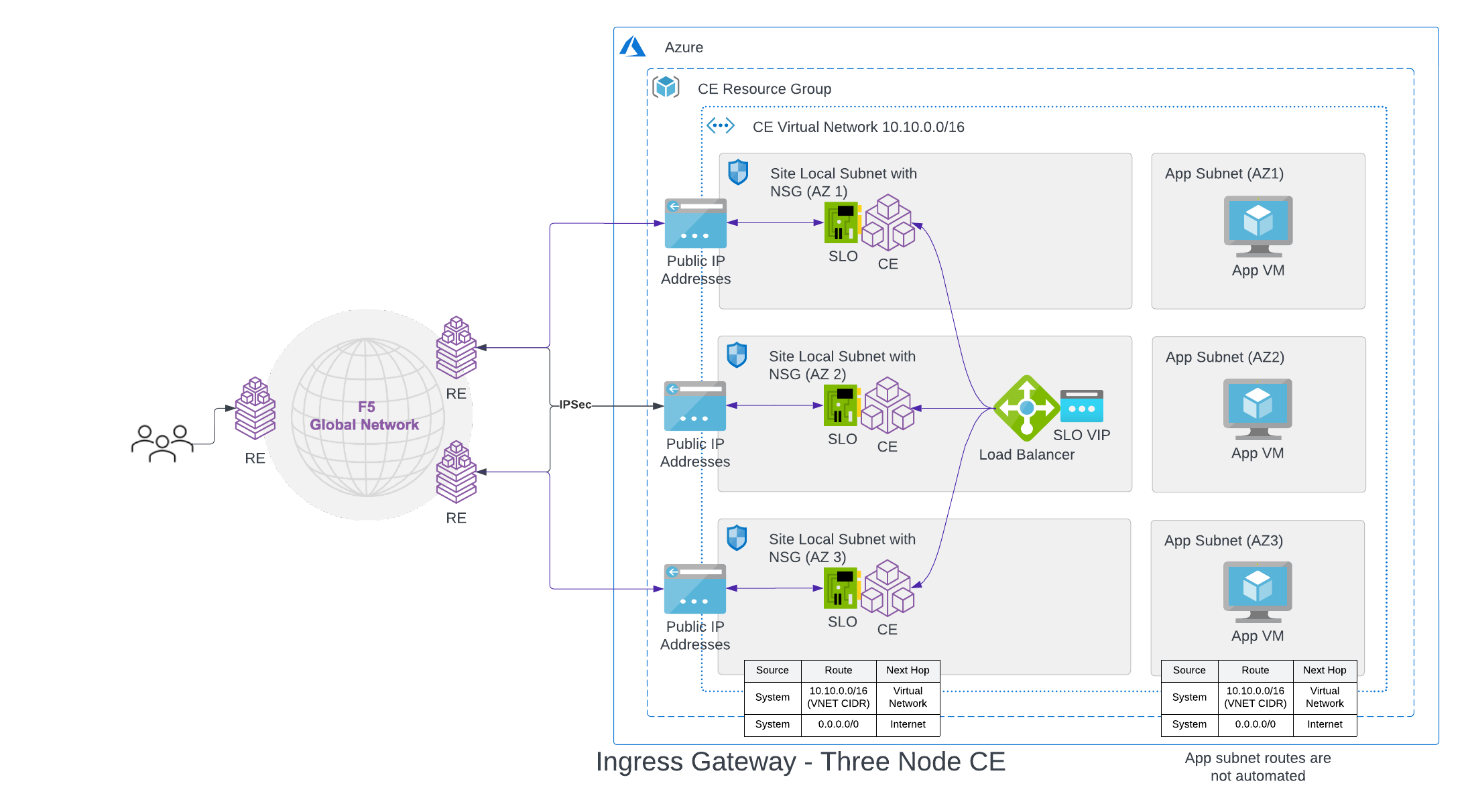
Figure: Azure Site Deployment - Ingress Gateway (One Interface)
Ingress/Egress Gateway (Two Interfaces)
In this deployment scenario, the Mesh nodes need two interfaces attached. The first interface is the outside interface through which services running on the node can connect to the Internet. The second interface is the inside interface which will become the default gateway IP address for all the application workloads and services present in the private subnets. There are two modes supported in this model: Standalone VNet and Hub VNet.
Standalone VNet
As a Standalone VNet, the application workloads are on private subnets, and they connect to Internet endpoints through Mesh instances, which have two legs: one on the outside network and another on the inside network.
As shown in the below figure, the outside interface is on the outside subnet which is associated with the outside subnet route table, whose default route is pointing to the Internet gateway. This interface can send and receive traffic from the Internet. In case of inside subnets, these are associated with the inside subnet route table which is also the main route table for this VNet, meaning that any newly created subnet in this VNet is automatically associated with the inside subnet route table. This private subnet route table has a default route pointing to the inside IP address of the Mesh node (192.168.0.186).
A three-node deployment diagram is shown below.
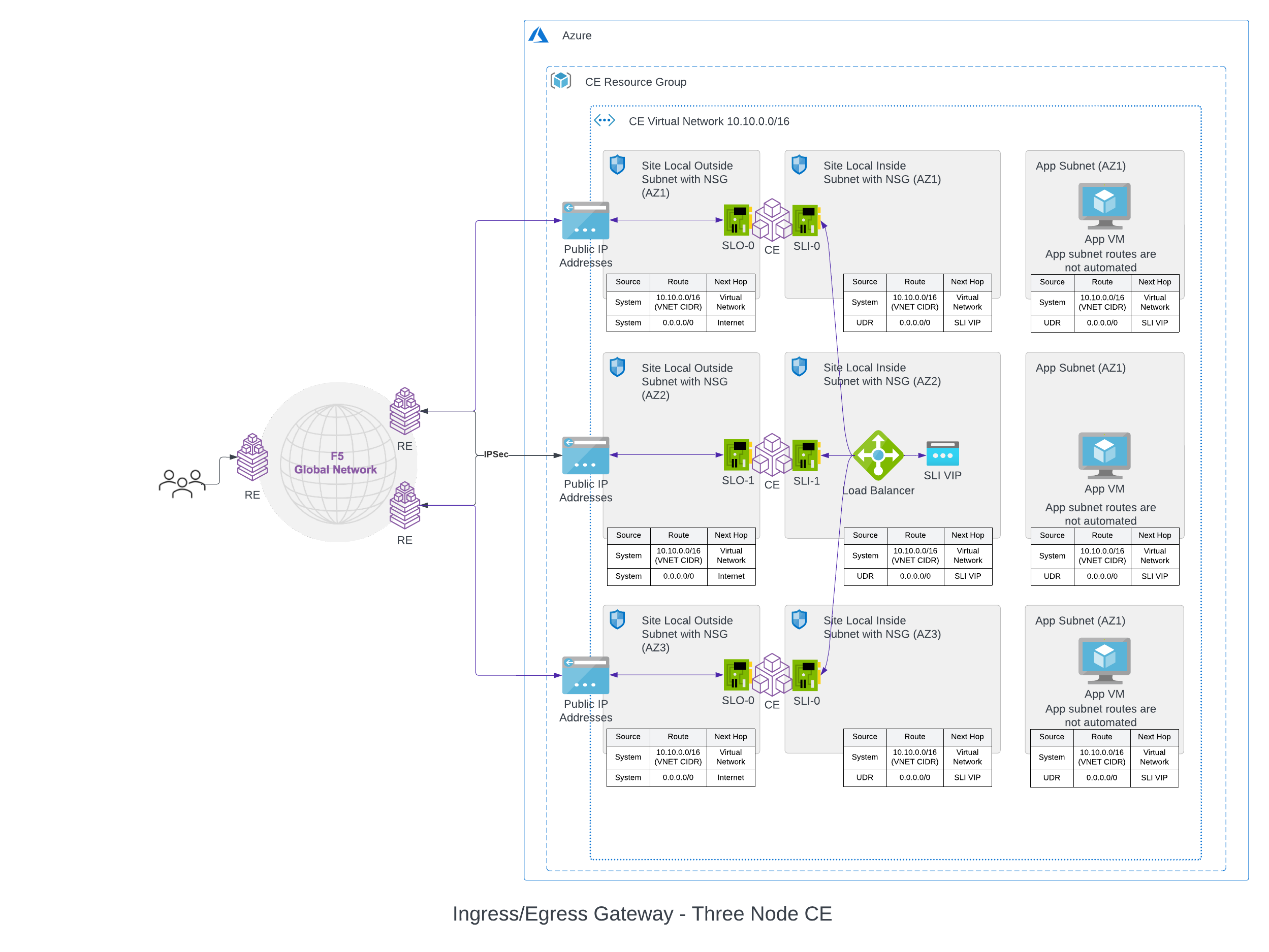
Figure: Azure Site Deployment - Ingress/Egress Gateway (Two Interfaces) Standalone VNet
Once the Mesh site comes online, the inside network of the node will be connected to the outside network through a forward proxy and SNAT enabled on the outside interface. All traffic destined to Internet endpoints that is coming on the inside interface will be forwarded to the Internet over the forward proxy and SNAT happening on the outside interface. Now all the workloads on the private workload subnet can reach the Internet through Mesh site.
Hub VNet
As a Hub VNet, application workloads are on one or more Spoke VNets, and they connect to this Hub VNet using VNet (Virtual Network) Peering. This Hub VNet has Distributed Cloud Services Mesh deployed, making it the central point of networking and security control for all the spoke VNets peered to it.
Currently, only the Virtual network peering is supported with the current release. This network connects virtual networks within the same Azure region. Only intra-region Spoke VNet peering is supported with the current release.
For more information, see Azure Virtual network peering.
As shown in the figure below, the Hub VNet has Distributed Cloud Services Mesh deployed along with Azure Load Balancer resource on the inside subnet. This Hub VNet can now be the ingress/egress gateway for all the Spoke VNets that have peered with this Hub VNet. This Hub VNet has internal load balancer (Azure Load Balancer), which the Spoke VNets use as the next hop to route traffic to the Hub VNet. To connect the Spoke VNets to the Hub VNet, there are two options: Auto routing and manual routing. With auto routing, a default route pointing to Hub VNet is created for Spoke VNets. While with manual routing, you can manually configure route prefixes that need to be routed to the Hub VNet, directly on Azure. If the spoke VNet configuration has no custom route, then you can manage it through the Auto Routing option. If the spoke VNet has a custom route, then you can manage it through the Manual Routing option.
All traffic destined to Internet endpoints that are coming on the inside interface of the Hub VNet will be forwarded to the Internet over the forward proxy and SNAT happening on the outside interface. Now the workloads on Spoke VNets can reach the Internet through the Hub VNet, which is the central point of network and security control.
Note: Currently, one Hub VNet can peer with up to 100 Spoke VNets. Based on the number of Spoke VNets peered, the time taken to deploy such a site can increase up to 90 minutes.
A three-node deployment diagram is shown below.
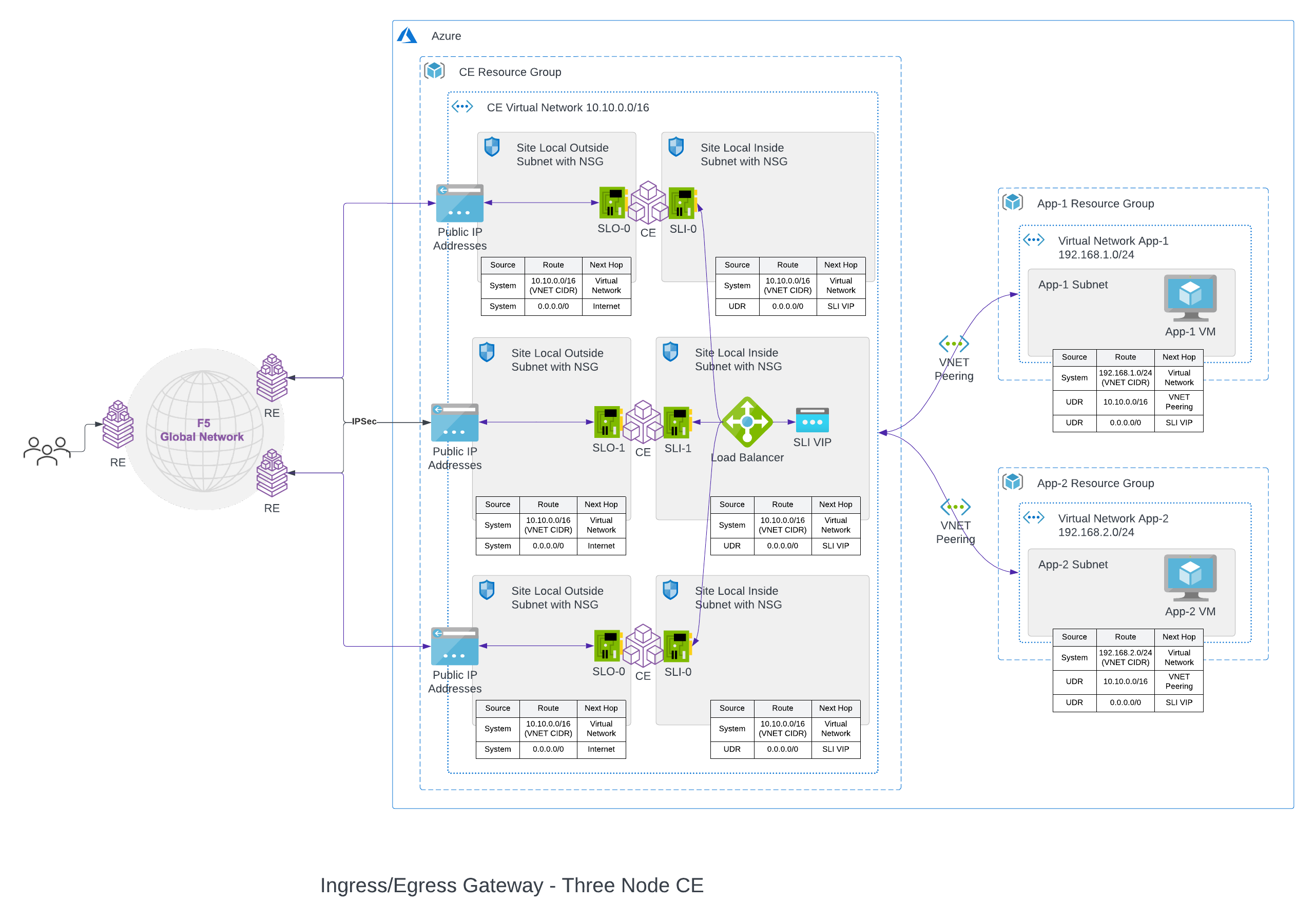
Figure: Azure Site Deployment - Ingress/Egress Gateway (Two Interfaces) Hub VNet
ExpressRoute
ExpressRoute enables you to extend your on-premises infrastructure or co-located environments to Azure data centers using a private connection that does not use the public Internet. ExpressRoute requires a connectivity provider, in this case F5 Distributed Cloud Services, to provide the backbone for all connections. The benefits of this include low latency, reduced costs, and high reliability when transferring data between your sites and the Azure private network. For more information, see the official product overview.
ExpressRoute uses BGP to exchange routes between your on-premises networks, your instances on Azure, and Microsoft public IP addresses. The connections to the Azure private network can be established using the peering locations and access regions within a geopolitical region. For example, if you have a Hub Site in North America, then you can connect to Azure in North America with ExpressRoute. This will give you access to all Azure cloud services hosted in North America.
A three-node deployment diagram is shown below.
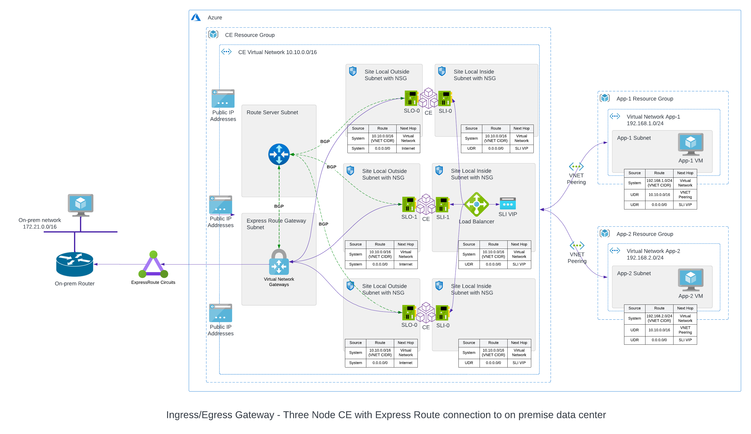
Figure: Azure ExpressRoute
ExpressRoute can only be used if deploying a site with the Ingress/Egress Gateway (Two Interfaces) option.
Four main components are required to use ExpressRoute:
-
Route Server: This is to dynamically exchange routes between the Customer Edge site and Azure using BGP. This connection is created inside the Hub VNet during initial configuration in Console.
-
Virtual Network Gateway: Only one is required per VNet. Microsoft provides different SKUs each with different CPU and bandwidth options. This network gateway is created inside the Hub VNet during initial configuration in Console.
-
ExpressRoute Circuit: This is a logical connection between an Azure Site and your on-premises data center or other co-located environments.
-
ExpressRoute Circuit Connection: This logical connection is established between the Virtual Network Gateway and ExpressRoute Circuit.
Network Policies
Distribute Cloud Services Mesh can be your ingress/egress security policy enforcement point, as all the traffic coming from private subnets will flow through the site. If the traffic does not match the type defined in network policy, then the default action will be to deny it.
You can define which endpoint/subnet by using the network policy. You can define the egress policy by adding the egress rules from the point of endpoint to deny/allow specific traffic patterns based on intent, and you can also add ingress rules to deny/allow traffic coming toward the endpoint.
Forward Proxy Policy
Using a forward proxy policy, you can specify allowed/denied TLS domains or HTTP URLs. The traffic from workloads on private subnets toward the Internet via the Azure VNet site is allowed or denied accordingly.
More details on how to configure this is captured in the rest of this documentation.
Site Status Descriptions
These descriptions provide information for the various stages of site deployment in Distributed Cloud Console. They also provide information to help you troubleshoot errors that may occur during the deployment and registration stages.
PLANNING: Site resources are being planned for creation.
PLAN_INIT_ERRORED: Planning of site resources failed at init stage.
PLAN_ERRORED: Planning of site failed with errors.
PLAN_QUEUED: Planning of site resources queued to be implemented.
APPLIED: Site resources are created, and site is waiting to come online.
APPLY_ERRORED: Creation of site resources failed with errors.
APPLY_INIT_ERRORED: Creation of site resources failed with errors at initial stage.
APPLYING: Site creation is in progress.
APPLY_PLANNING: Site resources are being planned.
APPLY_PLAN_ERRORED: Planning of site failed with errors.
APPLY_QUEUED: Creation of site resources queued to be implemented.
DESTROYED: Site resources are destroyed and site is OFFLINE.
DESTROY_ERRORED: Destroying of site resources failed with errors.
DESTROYING: Destroying of site resources in progress.
DESTROY_QUEUED: Destroying of site resources queued to be destroyed.
GENERATED: Site Object created in F5 Distributed Cloud Console database as per configuration.
TIMED_OUT: Creation/Destroying of site resources is failed with a timeout.
ERRORED: Creation/Destroying of site resources is failed with errors.
PROVISIONING: Site resources are created and waiting for site to come online.
Prerequisites
The following prerequisites apply:
-
A Distributed Cloud Services Account. If you do not have an account, see Getting Started with Console.
-
A Microsoft Azure Account. See Required Access Policies for permissions needed to deploy site. To create a cloud credentials object, see Create Cloud Credentials.
-
Resources required per node:
- vCPUs: Minimum 8 vCPUs.
- Memory: 32 GB RAM.
- Disk storage:
- Minimum 80 GB for Mesh site.
- Minimum 100 GB for App Stack site.
Note: For a full listing of the resources required, see the Customer Edge Site Sizing Reference guide. All the nodes in a given CE Site should have the same resources regarding the compute, memory, and disk storage. When deploying in cloud environments, these nodes should use the same instance flavor.
-
Instance type with Intel x86-based processor. ARM and Mac instances are not supported. Recommended instance types are:
- Standard_D8_v4
- Standard_D16_v4
-
Allow traffic from and to the Distributed Cloud public IP addresses to your network and allowlist related domain names. See F5 Customer Edge IP Address and Domain Reference for Firewall or Proxy Settings guide for the list of IP addresses and domain names.
-
Internet Control Message Protocol (ICMP) needs to be opened between the CE nodes on the Site Local Outside (SLO) interfaces. This is needed to ensure intra-cluster communication checks.
Important: After you deploy the CE Site, the IP address for the SLO interface cannot be changed. Also, the MAC address cannot be changed.
Deploy Using Console
You can create and manage an Azure VNet site in Console by first creating the site object using the guided wizard and then deploying it using the automated method.
Accept Subscription Agreement
Prior to beginning the site deployment process you must accept the Azure subscription agreement.
- Select the correct subscription:
az account set -s <subscription-id>- For ingress gateway site:
az vm image terms accept --publisher volterraedgeservices --offer volterra-node --plan volterra-node- For ingress/egress gateway site:
az vm image terms accept --publisher volterraedgeservices --offer entcloud_voltmesh_voltstack_node --plan freeplan_entcloud_voltmesh_voltstack_node_multinic- For F5® Distributed Cloud App Stack site:
az vm image terms accept --publisher volterraedgeservices --offer entcloud_voltmesh_voltstack_node --plan freeplan_entcloud_voltmesh_voltstack_nodeCreate Azure VNet Site Object
The wizard to create the Azure VNet site object guides you through the steps for required configuration.
Step 1: Start site object creation.
-
Log into Console.
-
From the Console homepage, select
Multi-Cloud Network Connect.
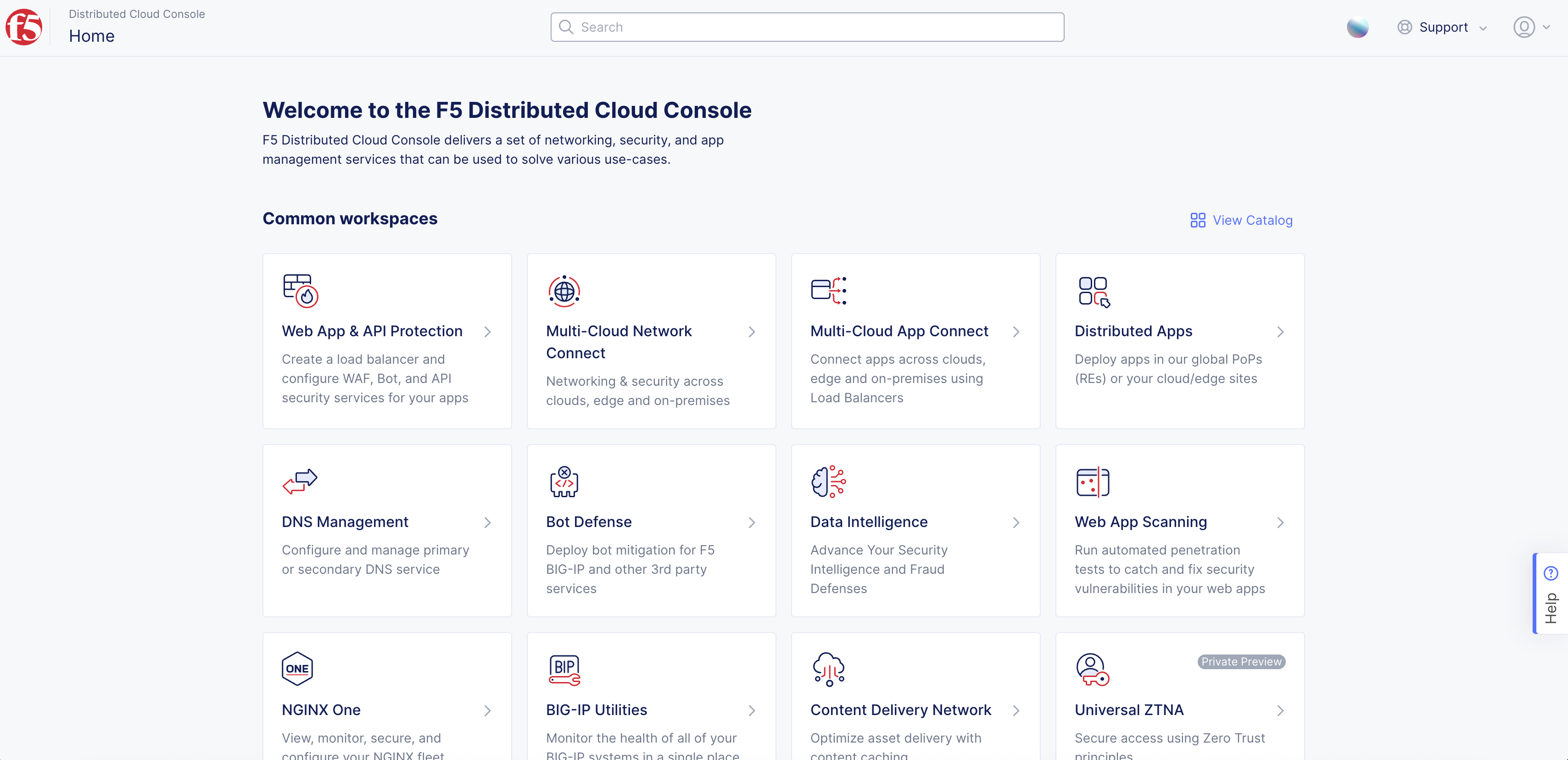
Figure: Console Homepage
-
Select
Manage>Site Management>Azure VNET Sites. -
Select
Add Azure VNET Site. -
In the
Metadatasection, enter a name. -
Optionally, select a label and add a description.
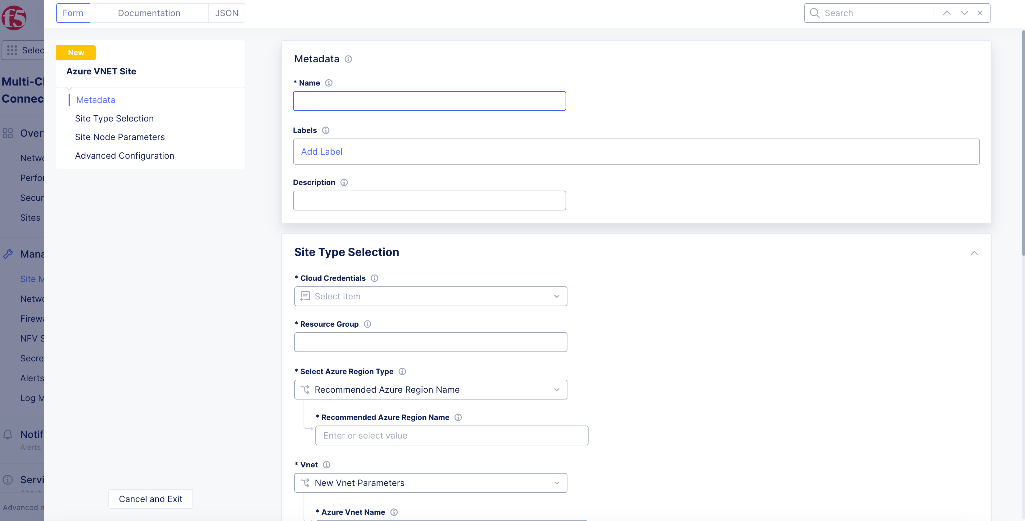
Figure: Azure Site Creation Form
Step 2: Select cloud credentials.
Refer to the Cloud Credentials guide for more information. Ensure that the Azure credentials are applied with required access policies per the Azure Credential Client Certificate or Azure Client Secret for Service Principal Credentials documents.
- From the
Cloud Credentialsmenu, select an existing Azure credentials object, or selectAdd Itemto load form.
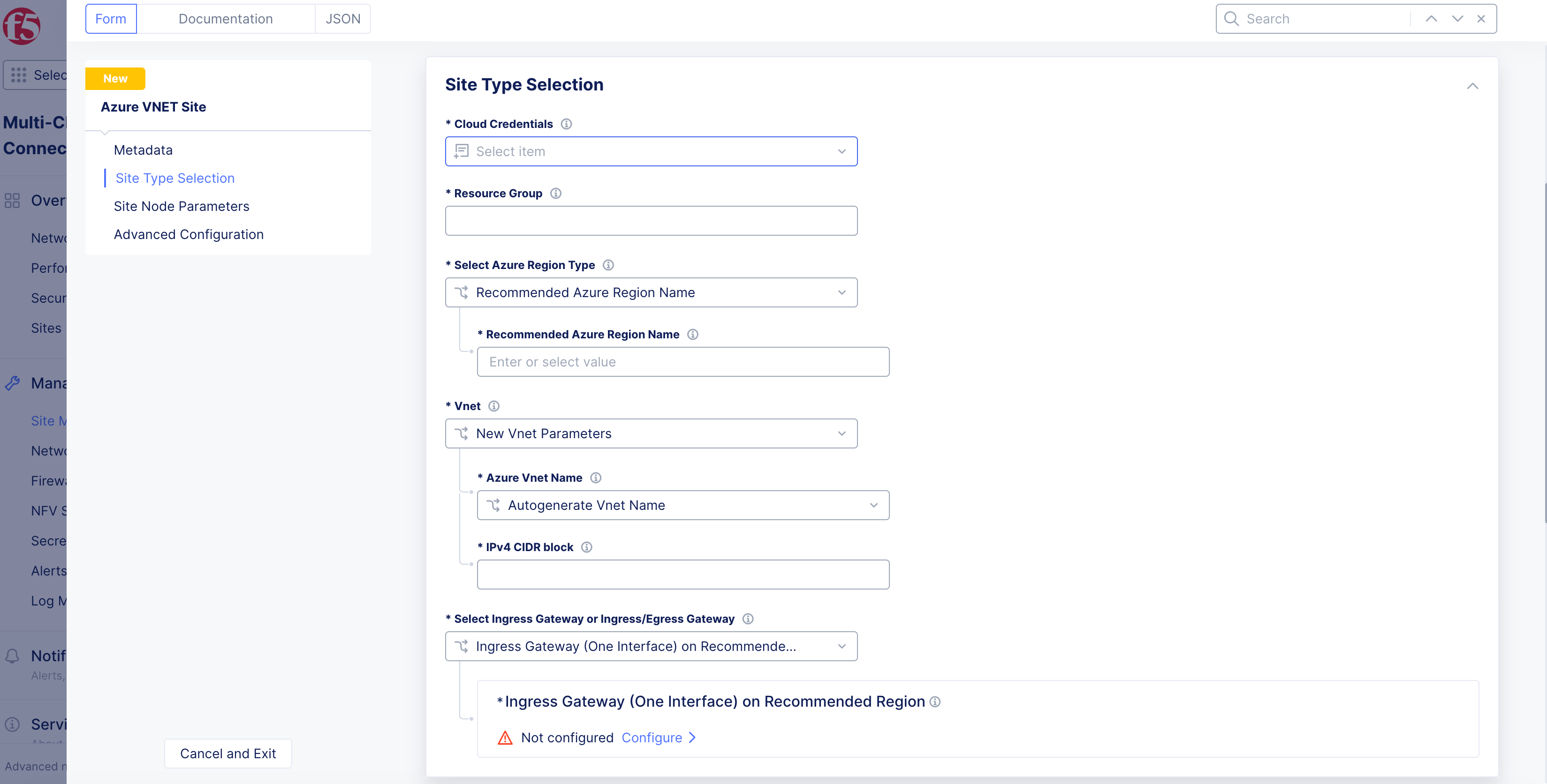
Figure: Cloud Credentials Option
-
To create new credentials:
-
Enter
Name,Labels, andDescriptionas needed. -
From the
Select Cloud Credential Typemenu, selectAzure Credential Client CertificateorAzure Client Secret for Service Principal. -
Enter the required information for each field marked with an asterisk (
*). -
Click
ConfigureforCertificate PasswordorAzure Client Secret, depending on your selection above. -
From the
Secret Typemenu:-
Blindfold Secret: Enter secret in theSecret to Blindfoldbox. -
Clear Secret: Enter secret in box in eitherTextorBase64formats. -
Click
Apply.
-
-
Click
Continueto add the new credentials.
-
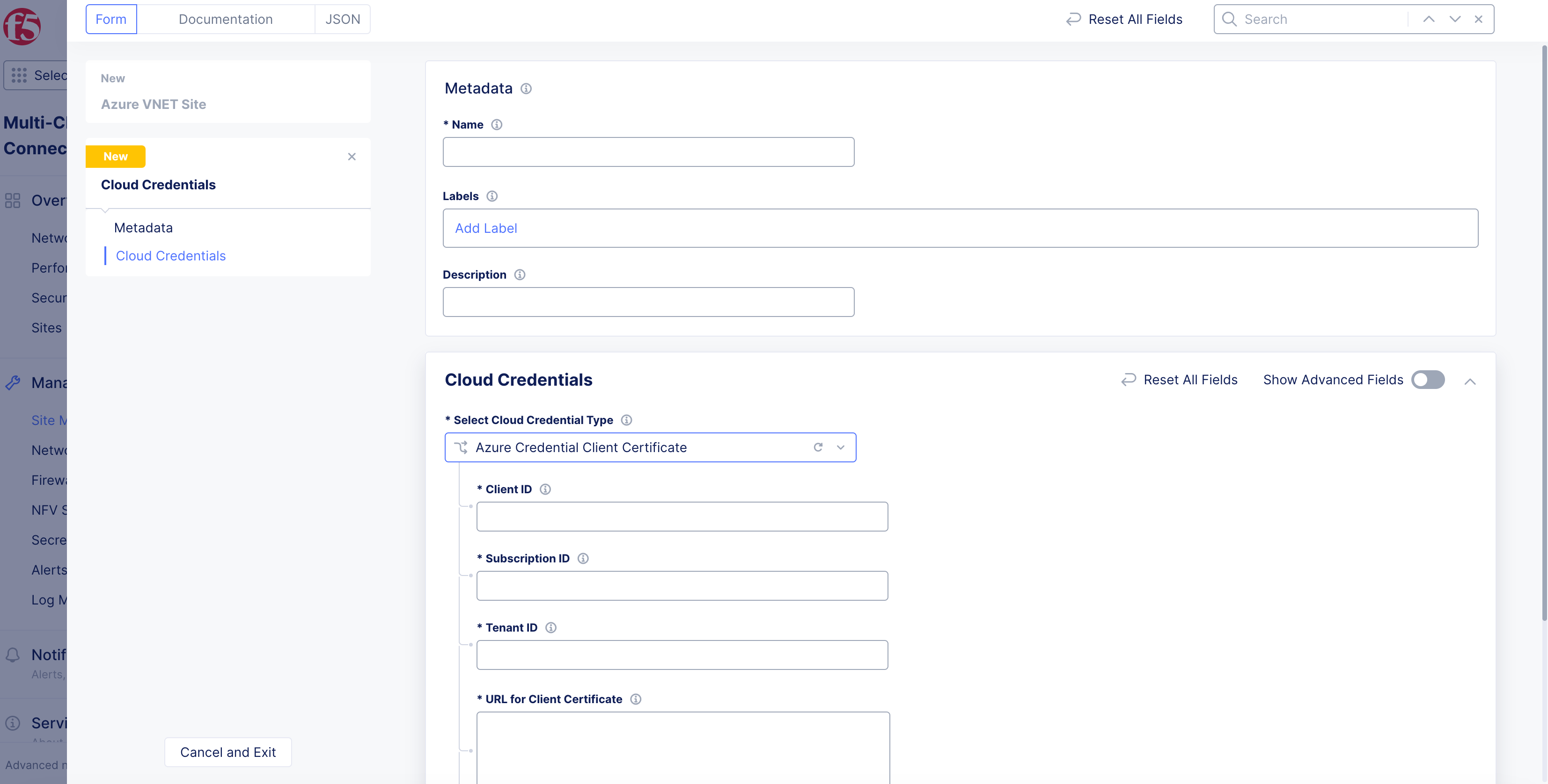
Figure: Azure Credential Creation Form
Step 3: Set Azure resource group and region.
-
In the
Site Type Selectionsection, enter the Azure resource group in theResource Groupfield. Ensure that you enter a name for a non-existent resource group. -
From the
Select Azure Region Typemenu, select a region type. TheRecommended Azure Region Nameoption is selected by default. You can change it by selecting theAlternate Azure Region Nameif you do not want to use an availability zone.
Note: The
Recommended Azure Region Nameoption is where Azure provides at least three availability zones. TheAlternate Azure Region Nameoption does not have three availability zones. For more information, see Regions and availability zones.
- Select a region from the
Recommended Azure Region NameorAlternate Azure Region Namemenu per your choice of the Azure region type.
Step 4: Configure VNet.
-
From the
Vnetmenu, select an option:New Vnet Parameters: SelectAutogenerate Vnet NameorChoose Vnet Namefrom theAzure Vnet Namemenu. If you choose a VNet name, enter the name in theChoose Vnet Namebox. In theIPv4 CIDR blockfield, enter a CIDR value.
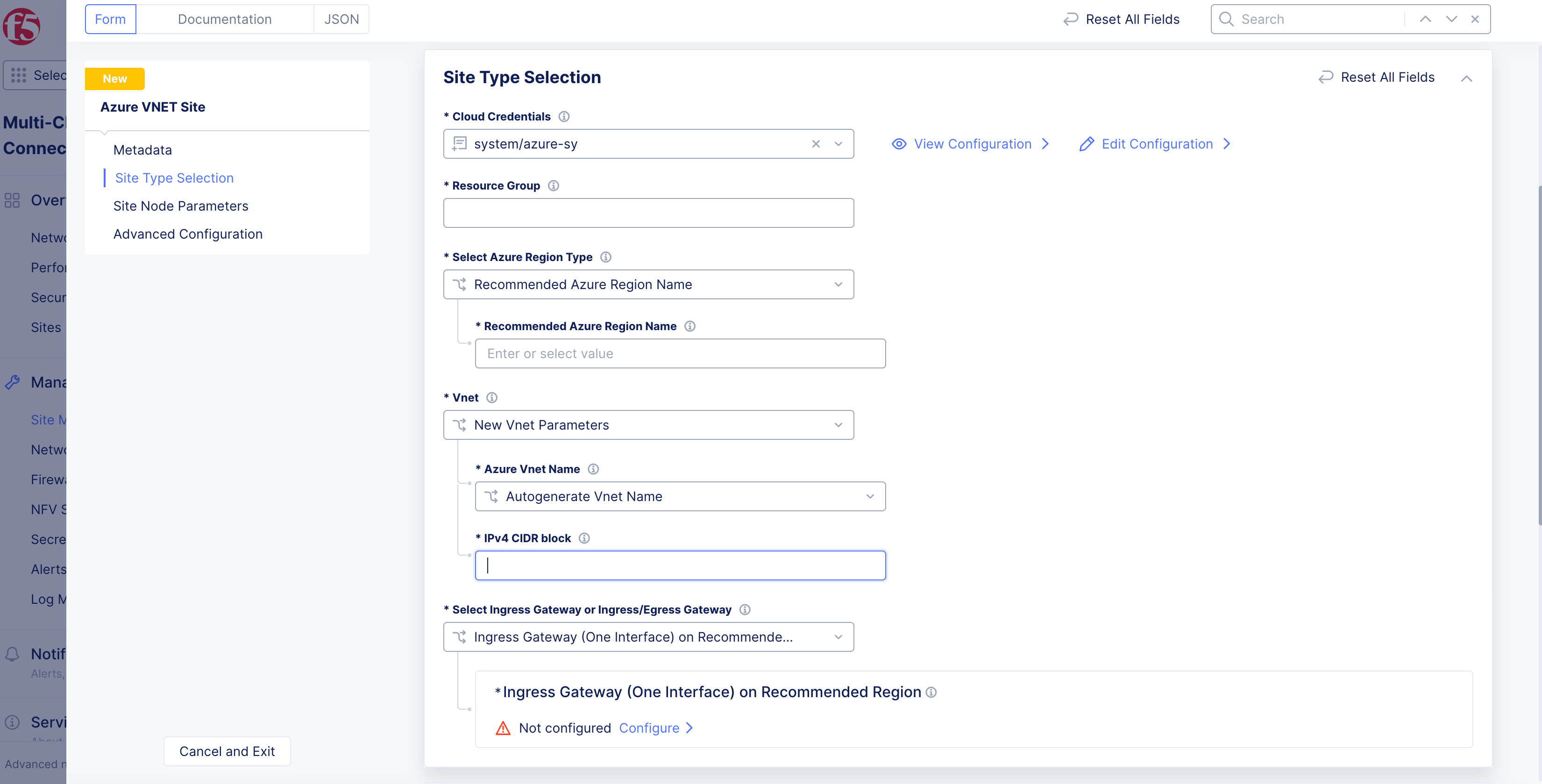
Figure: Site VNet Parameters
-
Existing Vnet: Enter an existing resource group name and VNet name in theExisting Vnet Resource GroupandExisting Vnet Namefields. In theIPv4 CIDR blockfield, enter a CIDR value. -
From the
Orchestrate VPC/VNET Routingmenu, select an option:-
F5 Orchestrated Routing: With this option, Distributed Cloud will automatically orchestrate the required routes for the SLO route table toward the public Internet and the SLI route table toward the CE. -
Manual Routing: With this option, Distributed Cloud will not orchestrate or alter any existing route tables or routes within existing VNet subnets. This option is ideal for better integration within existing environments.
-
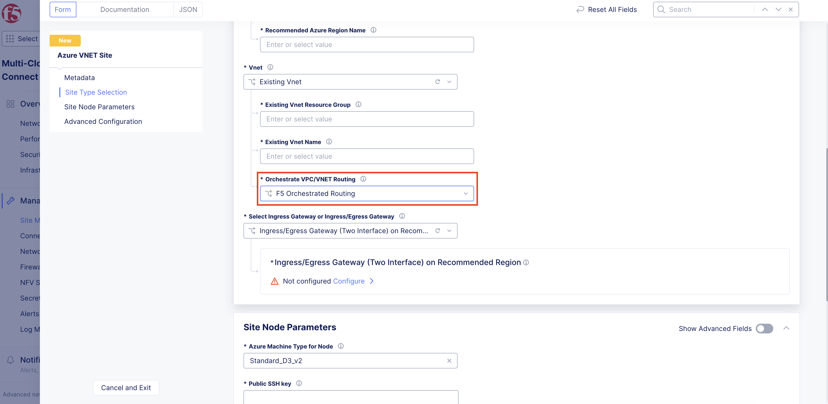
Figure: Routing Type Orchestration
Step 5: Set and configure site interface.
From the Select Ingress Gateway or Ingress/Egress Gateway menu, select an option per the configured Azure region type from above. For example, if you selected the region type as Alternate Azure Region Name and want to configure ingress gateway node, select the Ingress Gateway (One Interface) on Alternate Region option.
Important: The main difference between the recommended region and the alternate region is the following: In the recommended region, you can specify in which availability zone/subnet you will deploy each node. With the alternate region option, you will only specify how many nodes you want and the relevant subnet(s).
Ingress Gateway (one interface)
-
If you selected
Ingress Gateway (One Interface) on Recommended Region, performing the following:-
Select
Configure. -
Under the
Ingress Gateway (One Interface) Nodes in AZsection, clickAdd Item.
-
Note: Either a single control node site or a multi-node site with three (3) control nodes is supported. Therefore, if you are adding more than one node, ensure that there are three (3) control nodes for your site. Use
Add Itemto add more control nodes.
- From the
Azure AZ namemenu, select an option to set the number of availability zones.
Note: If you selected the
Ingress Gateway (One Interface) on Alternate Regionoption, you need to set the number of main nodes from theNumber of main nodesmenu.
-
From the
Subnet for local interfacemenu, select an option:-
For the
New Subnetoption, enter the subnet address in theIPv4 Subnetfield. -
For the
Existing Subnetoption, enter it in theSubnet Namefield, and select an option from theSubnet Resource Groupmenu. Use theVnet Resource Groupoption to use the same resource group as that of the VNet, or selectResource Group Nameand enter a name in theResource Group Namefield.
-
-
Select
Apply.
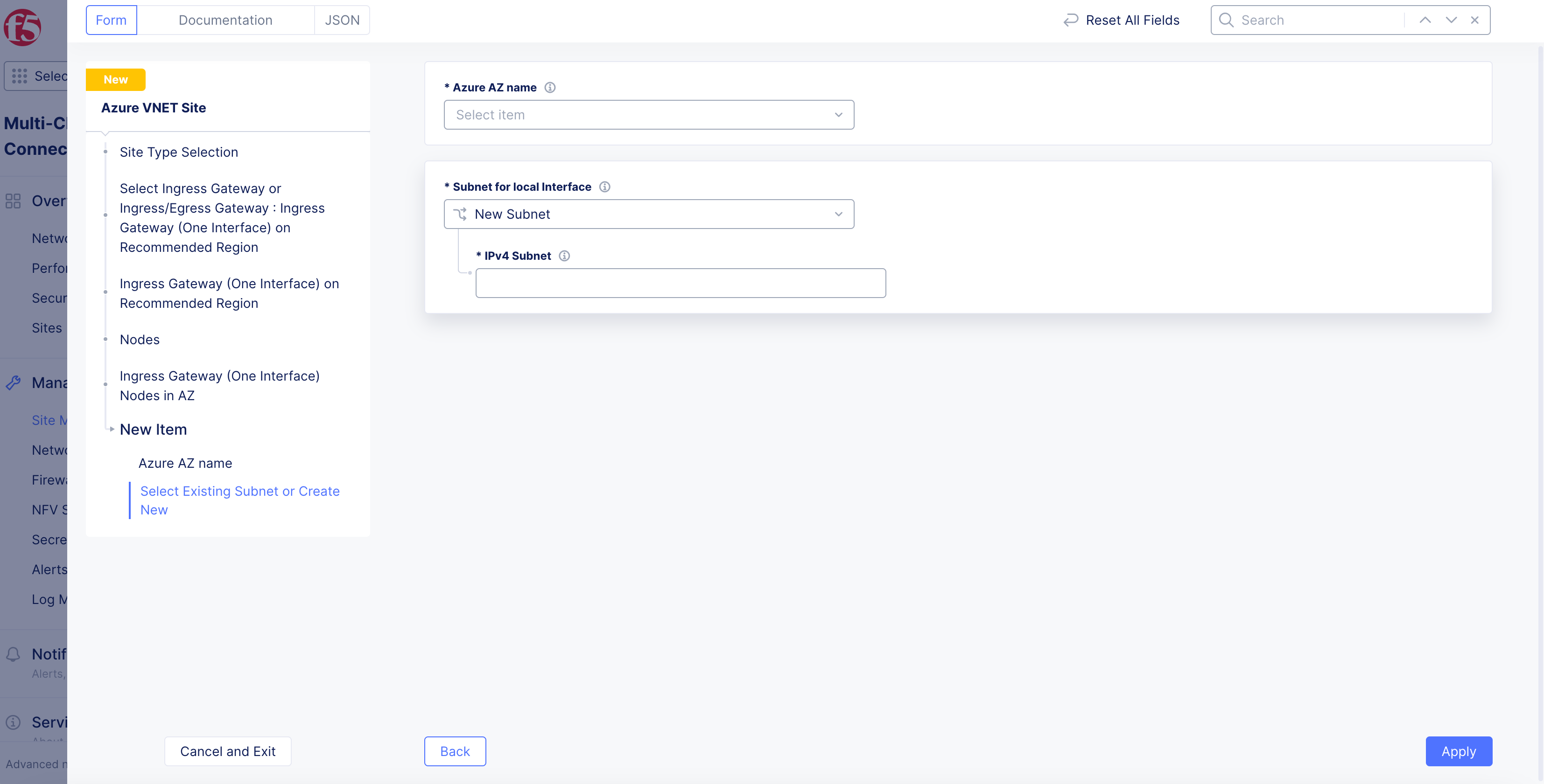
Figure: Ingress Gateway for One Interface
Note: You can add more than one ingress gateway using the
Add Itemoption.
-
Optionally, configure more settings in the
Advanced Optionssection:-
Enable the
Show Advanced Fieldsoption. -
From the
Performance Modemenu, select an option: -
L7 Enhanced: This option optimizes the site for Layer 7 traffic processing. -
L3 Enhanced: This option optimizes the site for Layer 3 traffic processing. -
To disable accelerated networking for your new virtual machine instances, select
Disable Accelerated Networkingfrom theAccelerated Networkingmenu.
-
Note: If enabled, this option will enable accelerated networking across all interfaces on all member nodes if the selected Azure virtual machine supports accelerated networking. The default setting for newly created Azure sites is to have accelerated networking enabled. For existing sites, there is no option to turn this feature on. After the site is created, the setting for accelerated networking cannot be changed. Currently, when enabling this option on a virtual machine that does not support it, you will get the error
VMSizeIsNotPermittedToEnableAcceleratedNetworkingduring the apply stage, suggesting other instance types that support the feature. To learn more about this feature, see Accelerated Networking overview To check if your VM instance size is supported, see Sizes for virtual machines in Azure.
- Select
Apply.
Ingress/Egress Gateway (two interfaces)
-
If you selected
Ingress/Egress Gateway (Two Interface) on Recommended Region, perform the following:-
Select
Configure. -
In the
Nodessection, clickAdd Item.
-
Note: Either a single control node site or a multi-node site with three (3) control nodes is supported. Therefore, if you are adding more than one node, ensure that there are three (3) control nodes for your site. Use
Add Itemto add more control nodes.
- From the
Azure AZ Namemenu, set the number of availability zones.
Note: If you selected the
Ingress/Egress Gateway (Two Interface) on Alternate Regionoption, you need to set the number of main nodes from theNumber of main nodesmenu.
-
From the
Subnet for Inside Interfacemenu, select an option to configure the subnet for inside interface:-
For the
New Subnetoption, enter a subnet address in theIPv4 Subnetfield. -
For the
Existing Subnetoption, enter an existing subnet in theSubnet Namefield and select an option from theSubnet Resource Groupmenu. Use theVnet Resource Groupoption to use the same resource group as that of the VNet, or selectResource Group Nameand enter a name in theResource Group Namefield. -
From the
Subnet for Outside Interfacemenu, select an option to configure the subnet for outside interface. Follow the instructions for the inside interface above. -
Select
Apply.
-
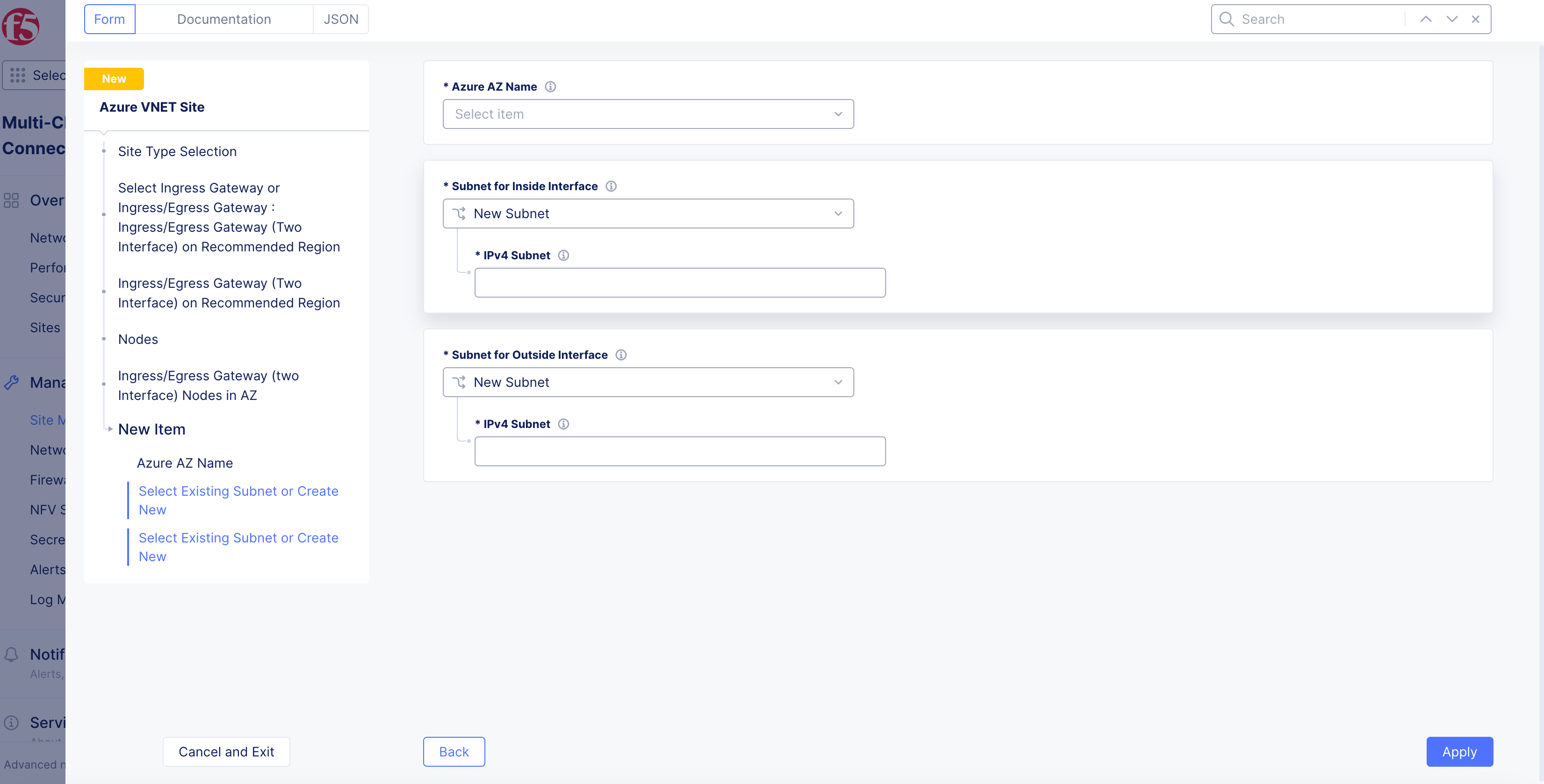
Figure: Ingress/Egress Gateway for Two Interfaces
-
Optionally, configure the network firewall settings in the
Site Network Firewallsection:-
From the
Manage Firewall Policymenu, add a firewall policy by selectingActive Firewall PoliciesorActive Enhanced Firewall Policies. Select an existing firewall policy, or selectAdd Itemto create and apply a firewall policy orConfigurefor an enhanced version. After creating the policy, clickContinueto apply. -
From the
Manage Forward Proxymenu, select an option: -
Enable Forward Proxy with Allow All Policy. -
Enable Forward Proxy and Manage Policies: Select an existing forward proxy policy, or selectAdd Itemto create and apply a forward proxy policy. After creating the policy, clickContinueto apply.
-
-
Optionally, configure more settings in the
Advanced Optionssection:-
From the
Select DC Cluster Groupmenu, select an option to set your site in a DC cluster group:-
Not a Member of DC Cluster Group: Default option. -
Member of DC Cluster Group via Outside Network: Select the DC cluster group from theMember of DC Cluster Group via Outside Networkmenu to connect your site using an outside network. -
Member of DC Cluster Group via Inside Network: Select the DC cluster group from theMember of DC Cluster Group via Inside Networkmenu to connect your site using an inside network.
-
-
Note: For more information, see the Configure DC Cluster Group guide.
-
From the
Select Performance Modemenu, select an option:-
L7 Enhanced: This option optimizes the site for Layer 7 traffic processing. -
L3 Enhanced: This option optimizes the site for Layer 3 traffic processing. -
To disable accelerated networking for your new virtual machine instances, select
Disable Accelerated Networkingfrom theAccelerated Networkingmenu.
-
Note: If enabled, this option will enable accelerated networking across all interfaces on all member nodes if the selected Azure virtual machine supports accelerated networking. The default setting for newly created Azure sites is to have accelerated networking enabled. For existing sites, there is no option to turn this feature on. After the site is created, the setting for accelerated networking cannot be changed. Currently, when enabling this option on a virtual machine that does not support it, you will get the error
VMSizeIsNotPermittedToEnableAcceleratedNetworkingduring the apply stage, suggesting other instance types that support the feature. To learn more about this feature, see Accelerated Networking overview To check if your VM instance size is supported, see Sizes for virtual machines in Azure.
- Select
Apply.
VNet Peering
-
To create a Spoke VNet:
- In Azure portal, create your Spoke VNets to use for virtual machine and container workloads.
-
To configure an ingress/egress Site into a Hub Site:
- Under the
Advanced Optionssection, selectHub VNetfrom theSelect VNet typedrop-down menu. This selection converts your Azure Site into a Hub Site.
- Under the
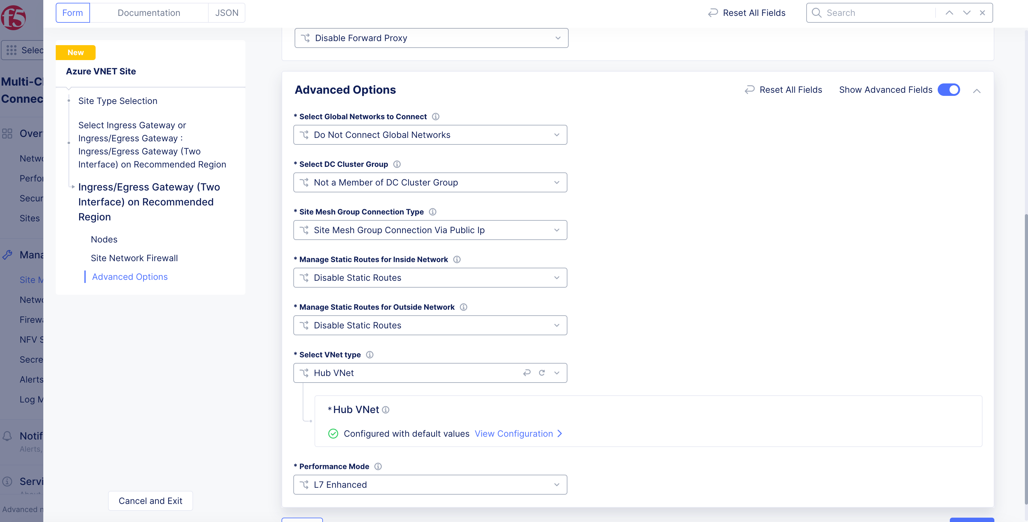
Figure: Choose Hub Option
-
Select
View Configuration. -
Select
Add Item.
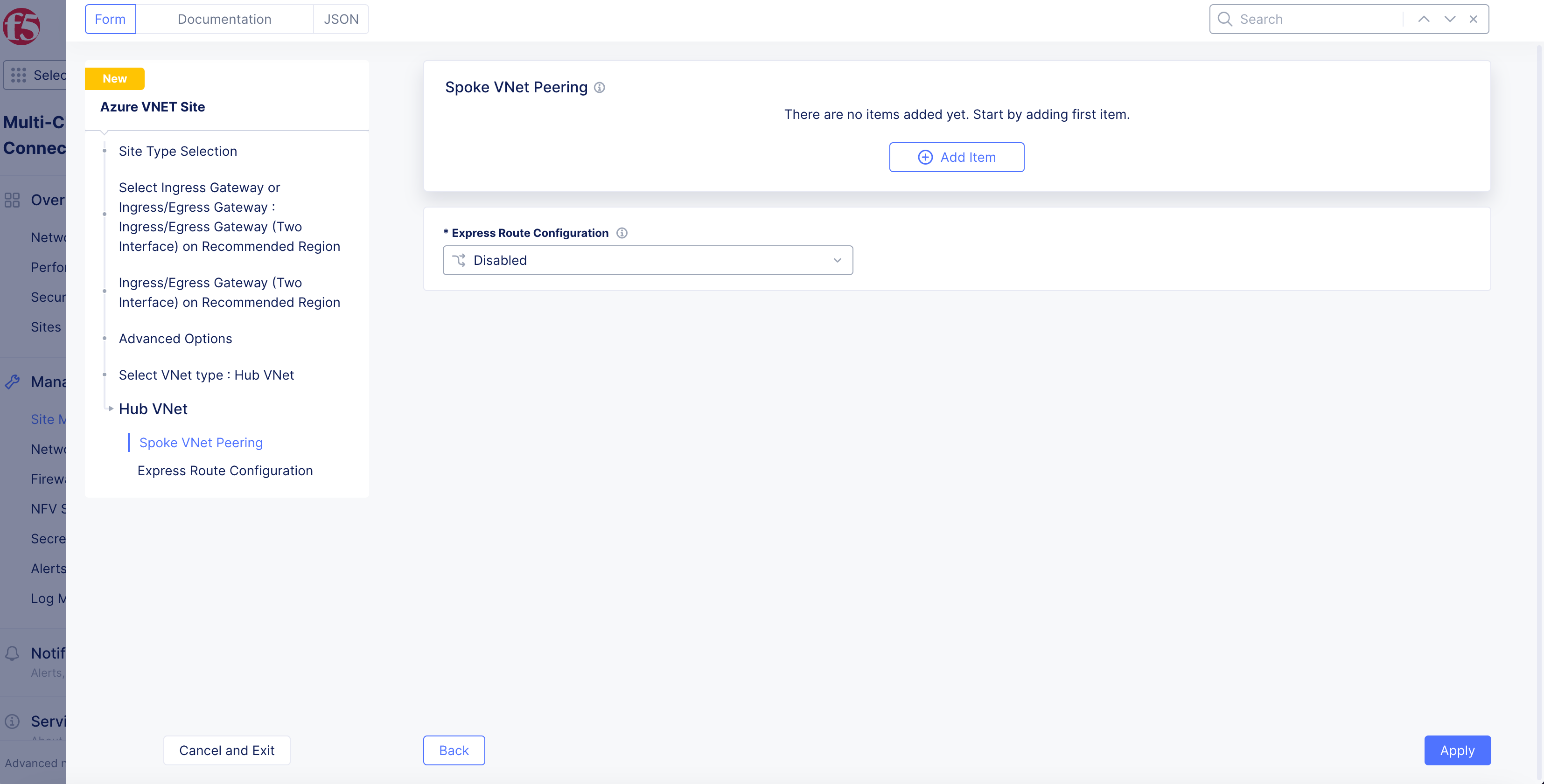
Figure: Add Spoke VNet
-
In the
Existing Vnet Resource Groupfield, enter the name of the Azure resource group of the Spoke VNet. -
In the
Existing Vnet Namefield, enter the name of the Spoke VNet. -
From the
Select automatic or manual configuration for routesmenu, select theAuto Routingoption to set up routing for all existing subnets on spoke VNet, or select theManual Routingoption to manually set up routing on the Spoke VNet. -
Select
Apply.
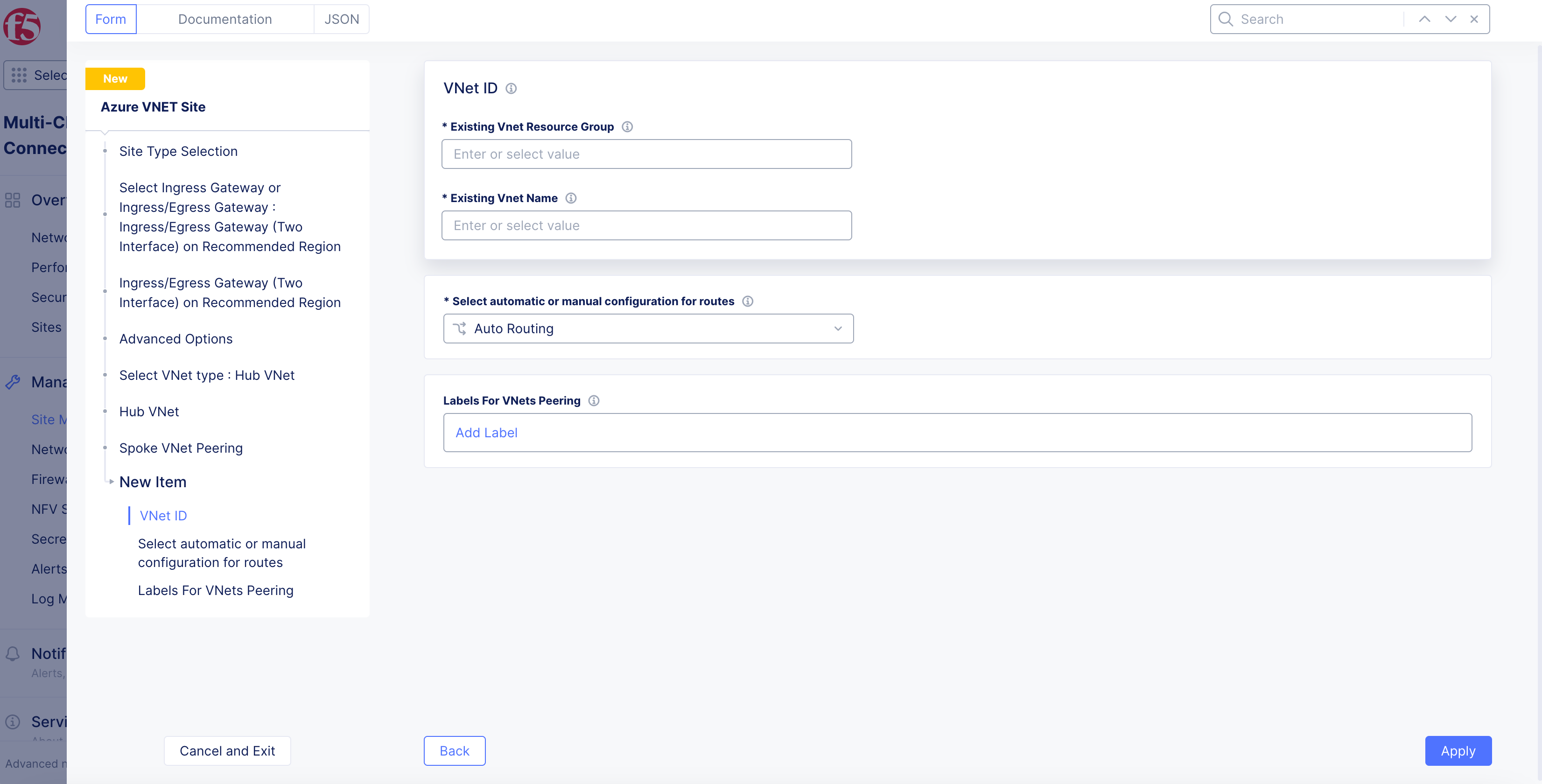
Figure: Add Spoke VNet
-
Select
Apply. -
Select
Apply. -
To verify status in Console, navigate to the hub site and select
...>Show VNET Peering Status.
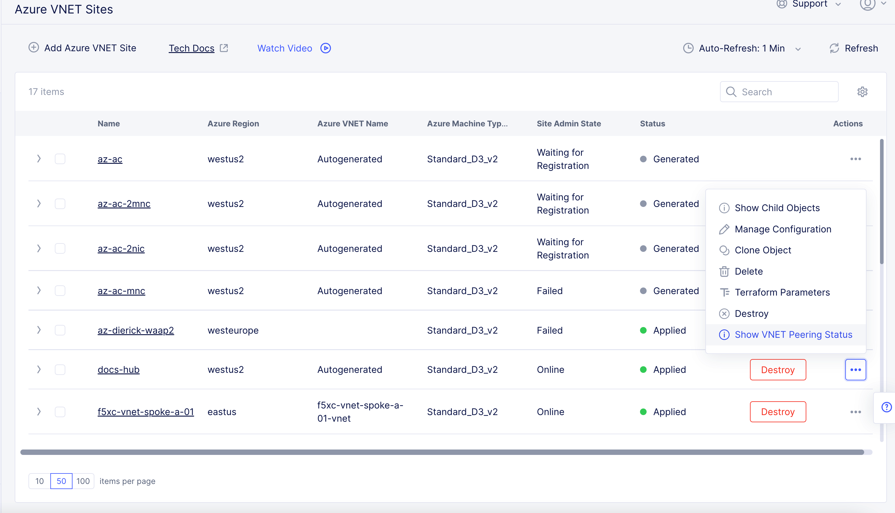
Figure: Peering Status
- Confirm the
"peering_sync_level"and"provisioning_state"fields are set to"FullyInSync"and"Succeeded", respectively.
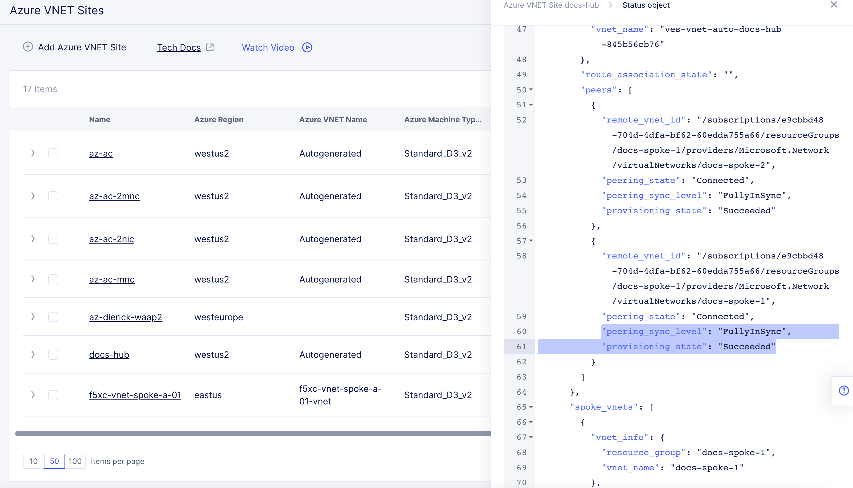
Figure: Peering Status
-
To verify status in Azure portal, confirm the VNets are online and then test connectivity.
-
To enable ExpressRoute:
- From the
Express Route Configurationmenu, selectEnabled.
- From the
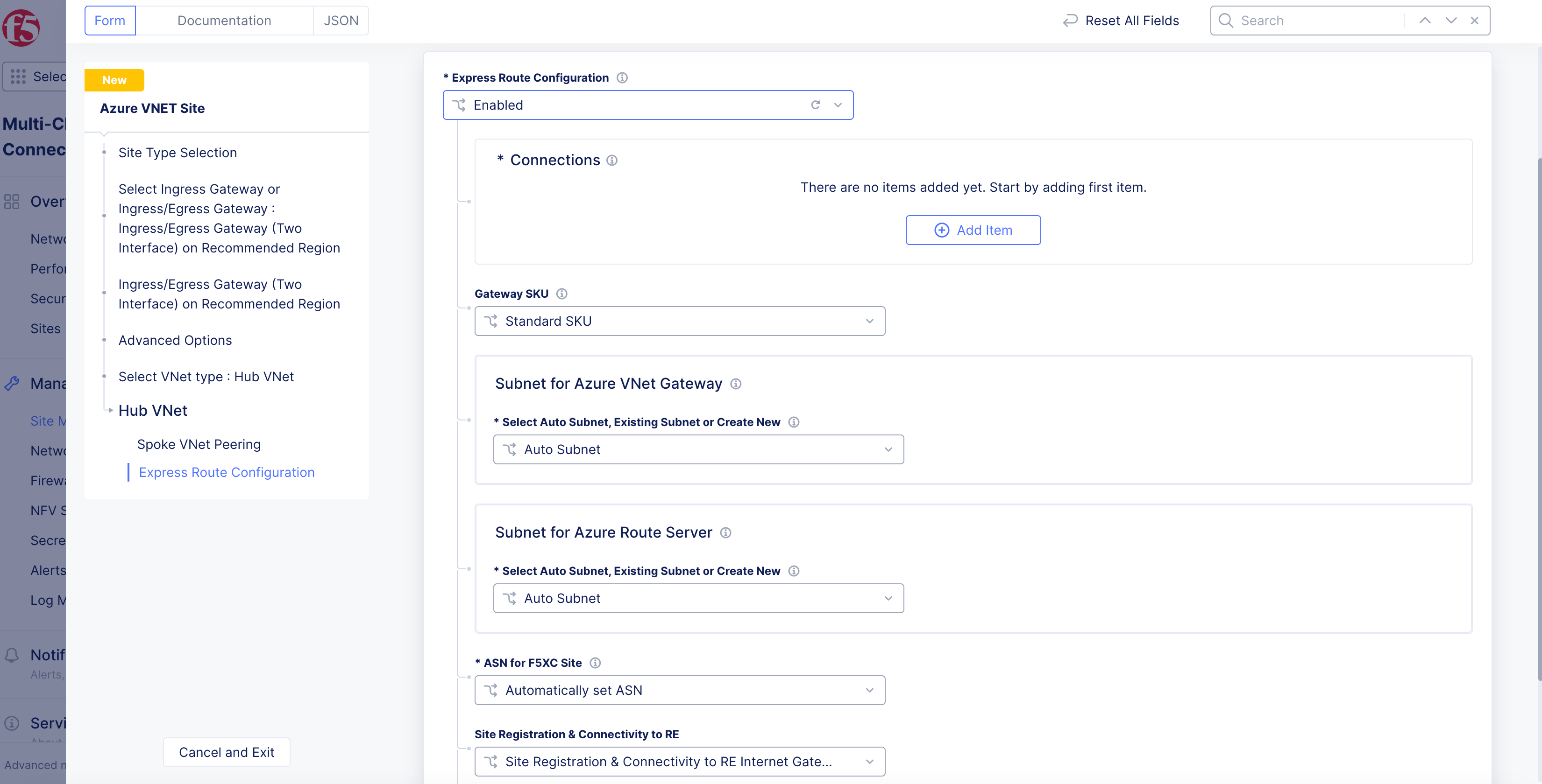
Figure: Enable ExpressRoute
-
Under the
Connectionssubsection, clickAdd Item. -
In the
Namefield, enter a name for this connection. -
From the
Express Route Circuit Configurationmenu, select whether this ExpressRoute is in the same subscription as the Site:-
Circuit in same subscription: Enter the subscription name. You can find this name in the Azure portal as theResource ID. -
Circuit in another subscription: EnterCircuit ID. You can find this ID in the Azure portal as theResource ID.
-
-
For the
Authorization Keyoption, clickConfigure. Enter theAuthorization Keyin the text box and then clickBlindfold. You can find this value in the Azure portal. SelectApplyto complete blindfold operation. -
Select
Applyto complete ExpressRoute configuration.
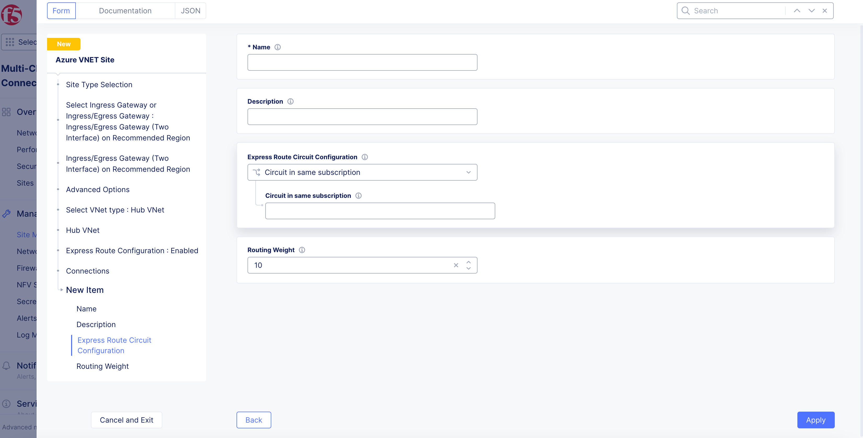
Figure: Enable ExpressRoute
-
From the
Gateway SKUmenu, select an option for gateway performance. -
For
Subnet for Azure VNet Gateway, select an option from theSelect Auto Subnet, Existing Subnet or Create Newmenu. Default option isAuto Subnet. If you selectNew Subnet, enter theIPv4 Subnet. If you selectExisting Subnet, enter theResource Group Name. -
For
Subnet for Azure Route Server, select an option from theSelect Auto Subnet, Existing Subnet or Create Newmenu. Default option isAuto Subnet. If you selectNew Subnet, enter theIPv4 Subnet. If you selectExisting Subnet, enter theResource Group Name. -
From the
ASN for F5XC Sitemenu, select an option to configure ASN for BGP between the Site and Azure Route Servers:-
Automatically set ASN: Default option. No extra configuration needed. Configuration is performed automatically. -
Custom ASN: Enter a custom ASN.
-
-
Select
Applyto apply ExpressRoute configuration. -
To view the status, go to your Azure Site and select
...>Show Express Route Status.
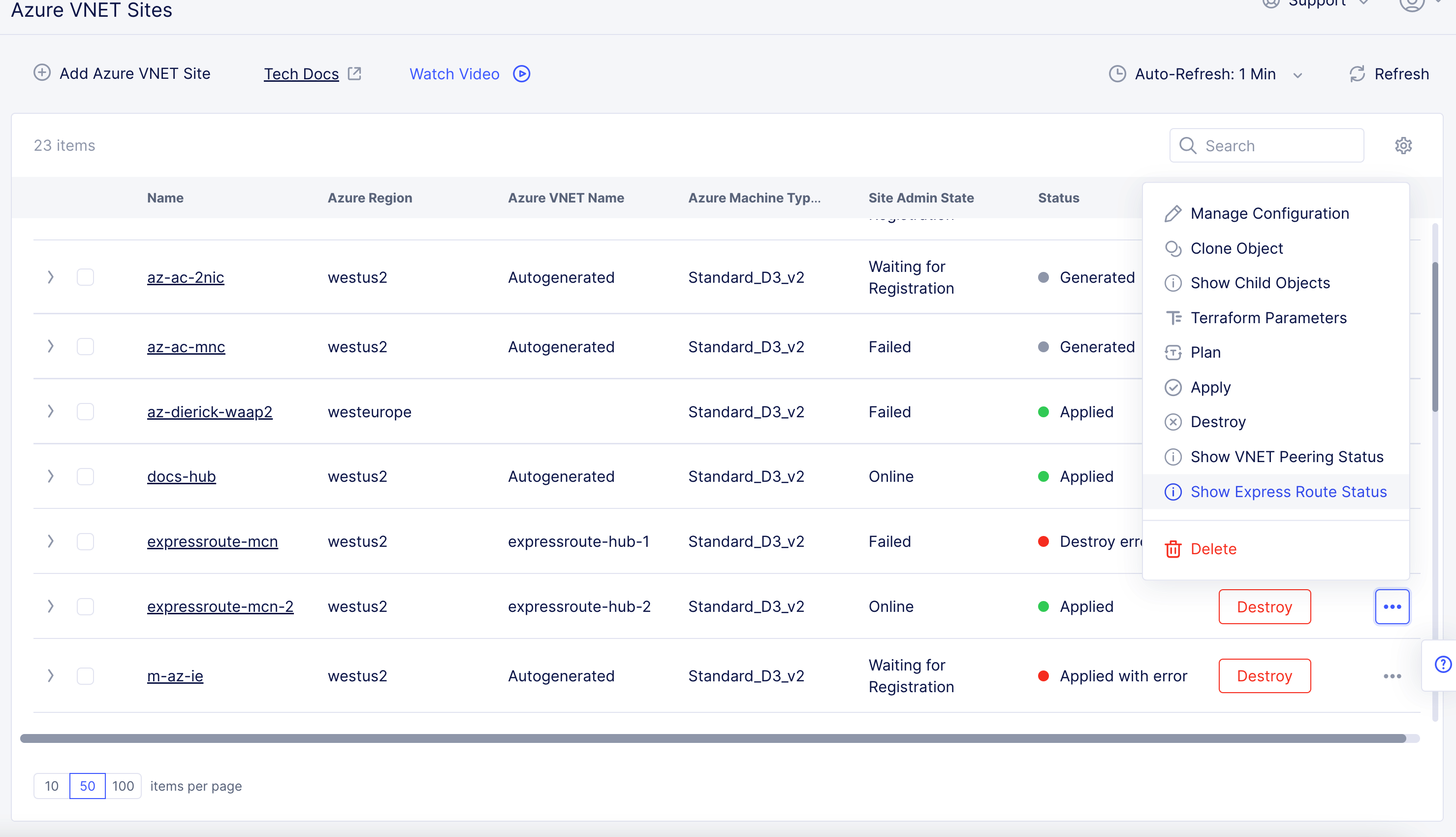
Figure: View ExpressRoute Status
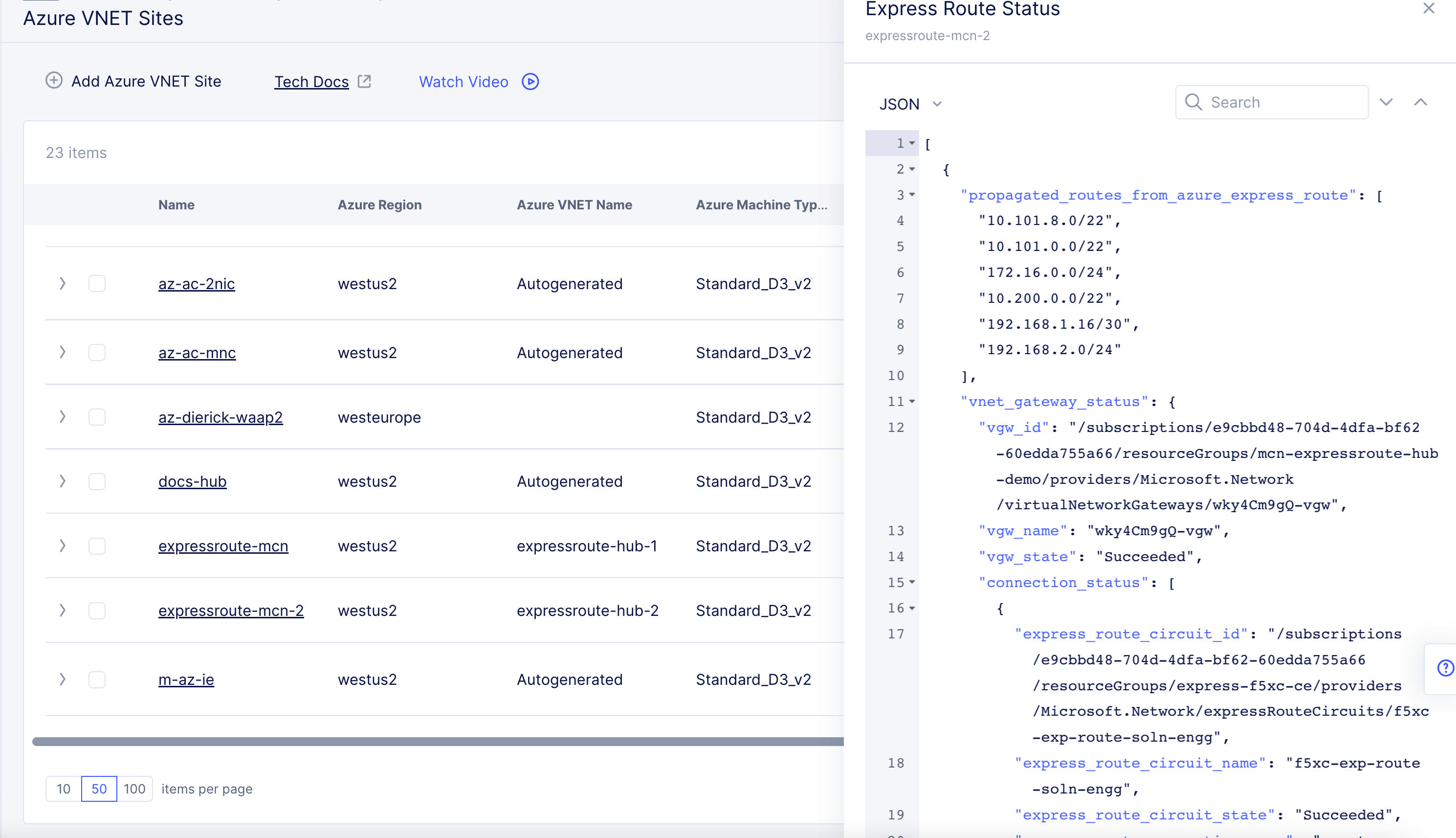
Figure: View ExpressRoute Status
App Stack Cluster (one interface)
-
If you selected
App Stack Cluster (One Interface) on Recommended Region, perform the following:-
Select
Configure. -
In the
App Stack Cluster (One Interface) Nodes in AZsection, clickAdd Item.
-
Note: Either a single control node site or a multi-node site with three (3) control nodes is supported. Therefore, if you are adding more than one node, ensure that there are three (3) control nodes for your site. Use
Add Itemto add more control nodes.
- From the
Azure AZ namemenu, set the number of availability zones.
Note: If you selected the
App Stack Cluster (One Interface) on Alternate Regionoption, you need to set the number of main nodes from theNumber of main nodesmenu.
-
From the
Subnet for local interfacemenu, select an option to configure the subnet for inside interface:-
For the
New Subnetoption, enter a subnet address in theIPv4 Subnetfield. -
For the
Existing Subnetoption, enter an existing subnet in theSubnet Namefield and select an option from theSubnet Resource Groupmenu. Use theVnet Resource Groupoption to use the same resource group as that of the VNet, or selectResource Group Nameand enter a name in theResource Group Namefield. -
From the
Subnet for Outside Interfacemenu, select an option to configure the subnet for outside interface manually. Follow the instructions for the inside interface above.
-
-
Select
Apply.
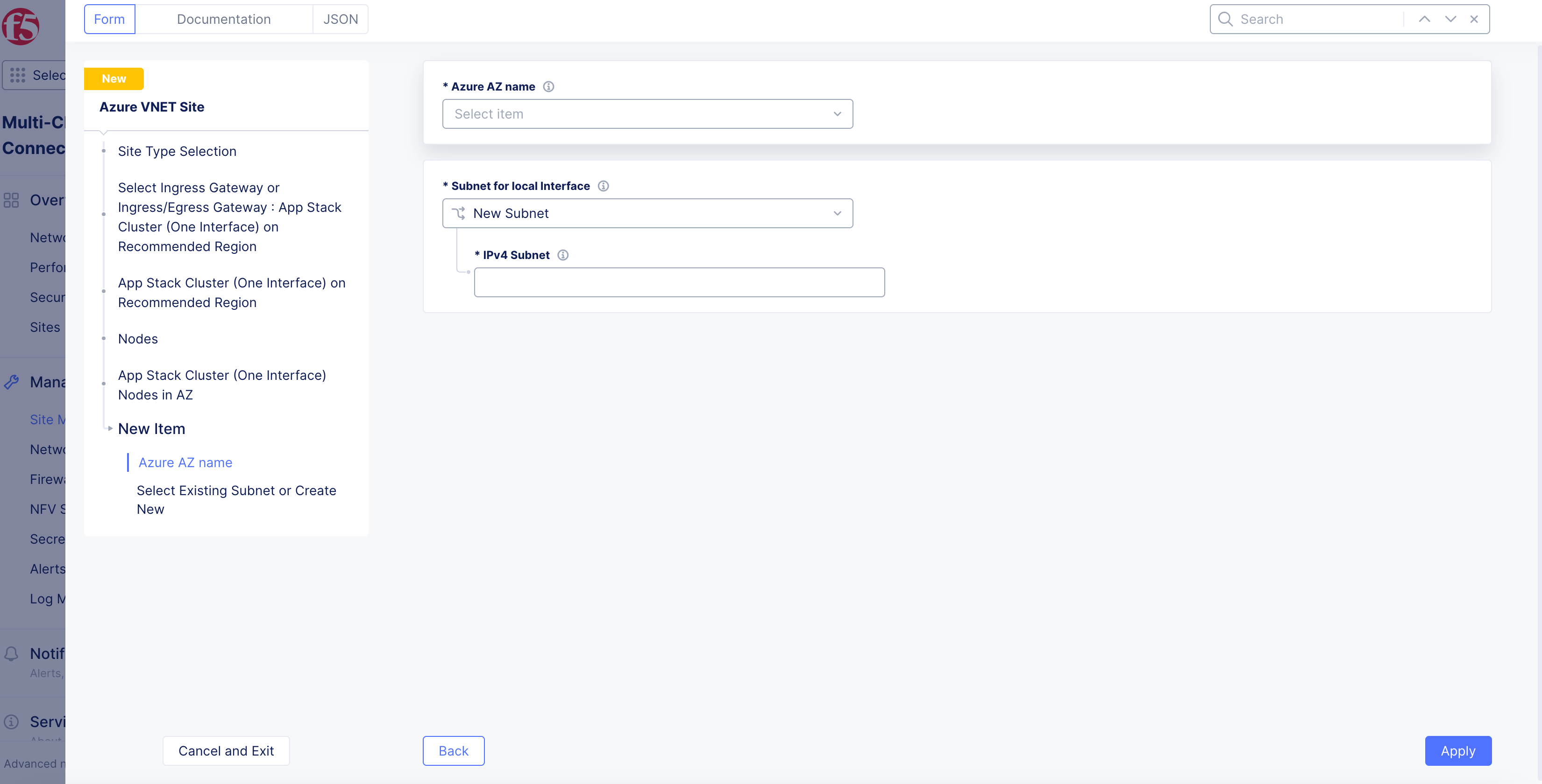
Figure: App Stack Cluster for One Interface
-
Optionally, configure the network firewall settings in the
Site Network Firewallsection:-
From the
Manage Firewall Policymenu, add a firewall policy by selectingActive Firewall PoliciesorActive Enhanced Firewall Policies. Select an existing firewall policy, or selectAdd Itemto create and apply a firewall policy orConfigurefor an enhanced version. After creating the policy, clickContinueto apply. -
From the
Manage Forward Proxymenu, select an option: -
Enable Forward Proxy with Allow All Policy. -
Enable Forward Proxy and Manage Policies: Select an existing forward proxy policy, or selectAdd Itemto create and apply a forward proxy policy. After creating the policy, clickContinueto apply.
-
-
In the
Storage Configurationsection, enable theShow Advanced Fieldsoption. -
From the
Select Configuration for Storage Classesmenu, selectAdd Custom Storage Class. Perform the following:-
Select
Add Item. -
In the
Storage Class Namefield, enter a name for the storage class as it will appear in Kubernetes. -
Optionally, enable the
Default Storage Classoption to make this new storage class the default class for all clusters. -
Click
Apply.
-
-
In the
Advanced Optionssection, from theSelect DC Cluster Groupmenu, select an option to set the site in a DC cluster group:-
Not a Member: Default option. -
Member of DC Cluster Group: Select the DC cluster group from theMember of DC Cluster Groupmenu to connect the site using an outside network.
-
Note: For more information, see the Configure DC Cluster Group guide.
- In the
Advanced Optionssection: To disable accelerated networking for your new virtual machine instances, selectDisable Accelerated Networkingfrom theAccelerated Networkingmenu.
Note: If enabled, this option will enable accelerated networking across all interfaces on all member nodes if the selected Azure virtual machine supports accelerated networking. The default setting for newly created Azure sites is to have accelerated networking enabled. For existing sites, there is no option to turn this feature on. After the site is created, the setting for accelerated networking cannot be changed. Currently, when enabling this option on a virtual machine that does not support it, you will get the error
VMSizeIsNotPermittedToEnableAcceleratedNetworkingduring the apply stage, suggesting other instance types that support the feature. To learn more about this feature, see Accelerated Networking overview To check if your VM instance size is supported, see Sizes for virtual machines in Azure.
- Click
Apply.
Step 6: Optionally, set the site node parameters.
-
In the
Site Node Parameterssection, enable theShow Advanced Fieldsoption. -
From the
Azure Machine Type for Nodemenu, set the Azure machine type by selecting an option. ClickSee Common Values. -
Specify a disk size in GiB from the
Cloud Disk Sizemenu. For example, 80 would be 80 GiB. -
In the
Public SSH keybox, enter the public key used for SSH purposes.
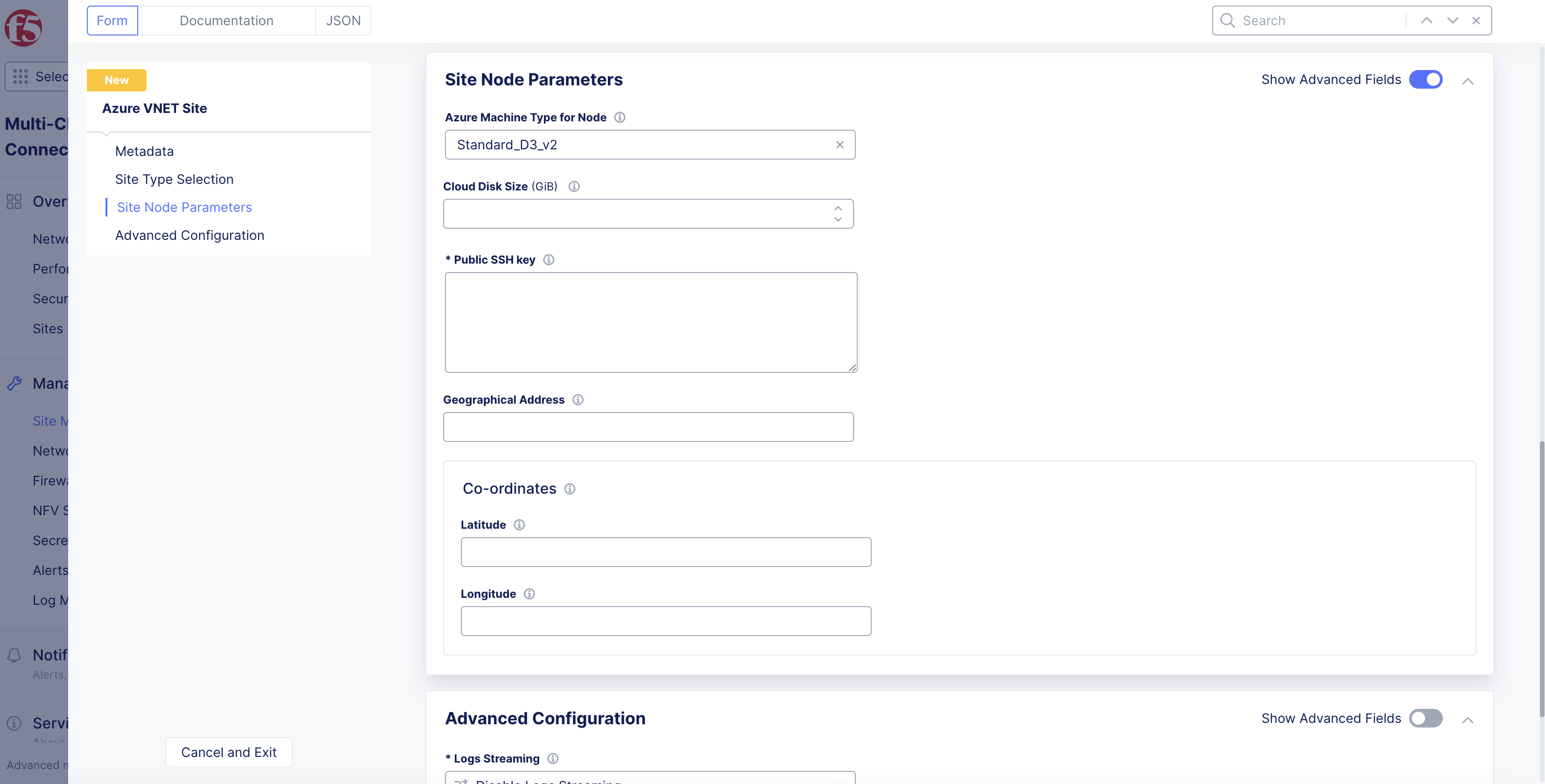
Figure: Azure VNet Site Node Parameters
-
Enter a geographic address in the
Geographical Addressfield to determine the latitude and longitude. -
Specify the latitude and longitude using
LatitudeandLongitudein theCo-ordinatessection.
Step 7: Optionally, configure the advanced options.
-
Toggle the
Show Advanced Fieldsoption in theAdvanced Configurationsection. -
Select
Enable Log Streamingfrom theLogs Streamingmenu:- From the
Enable Logs Streamingmenu, select an existing log receiver, or clickAdd Item.
- From the
-
From the
F5XC Software Versionmenu, set the latest or a specific version for Distributed Cloud Services software:F5XC Software Version: Enter the specific version in theF5XC Software Versionfield, if selected.
-
From the
Operating System Versionmenu, set the latest or a specific version for the operating system:Operating System Version: Enter the specific version in theOperating System Versionfield, if selected.
-
From the
Node by Node Upgrademenu, keep the default selection ofEnableto ensure your CE nodes are updated efficiently and in parallel with one another. Configure the corresponding options to suite your requirements. -
For the
Azure Tagsoption, useAdd Labelto link sites together using a label. A maximum of thirty (30) tags are supported per instance. -
From the
Desired Worker Nodes Selectionmenu, select worker node configuration:-
Desired Worker Nodes Per AZ: To specify worker nodes per availability zone, enter the number of worker nodes per zone in theDesired Worker Nodes Per AZfield. A maximum of twenty-one (21) zones is allowed. -
Total Number of Worker Nodes for a Site: To specify the total number of worker nodes across all zones of a site, enter the number in theTotal Number of Worker Nodes for a Sitefield. This specifies the number of worker nodes you want automation to automatically place evenly across the availability zones.
-
Note: For an Azure alternate region, there is no availability zone. F5 recommends that you use the
Total Number of Worker Nodes for a Siteoption.
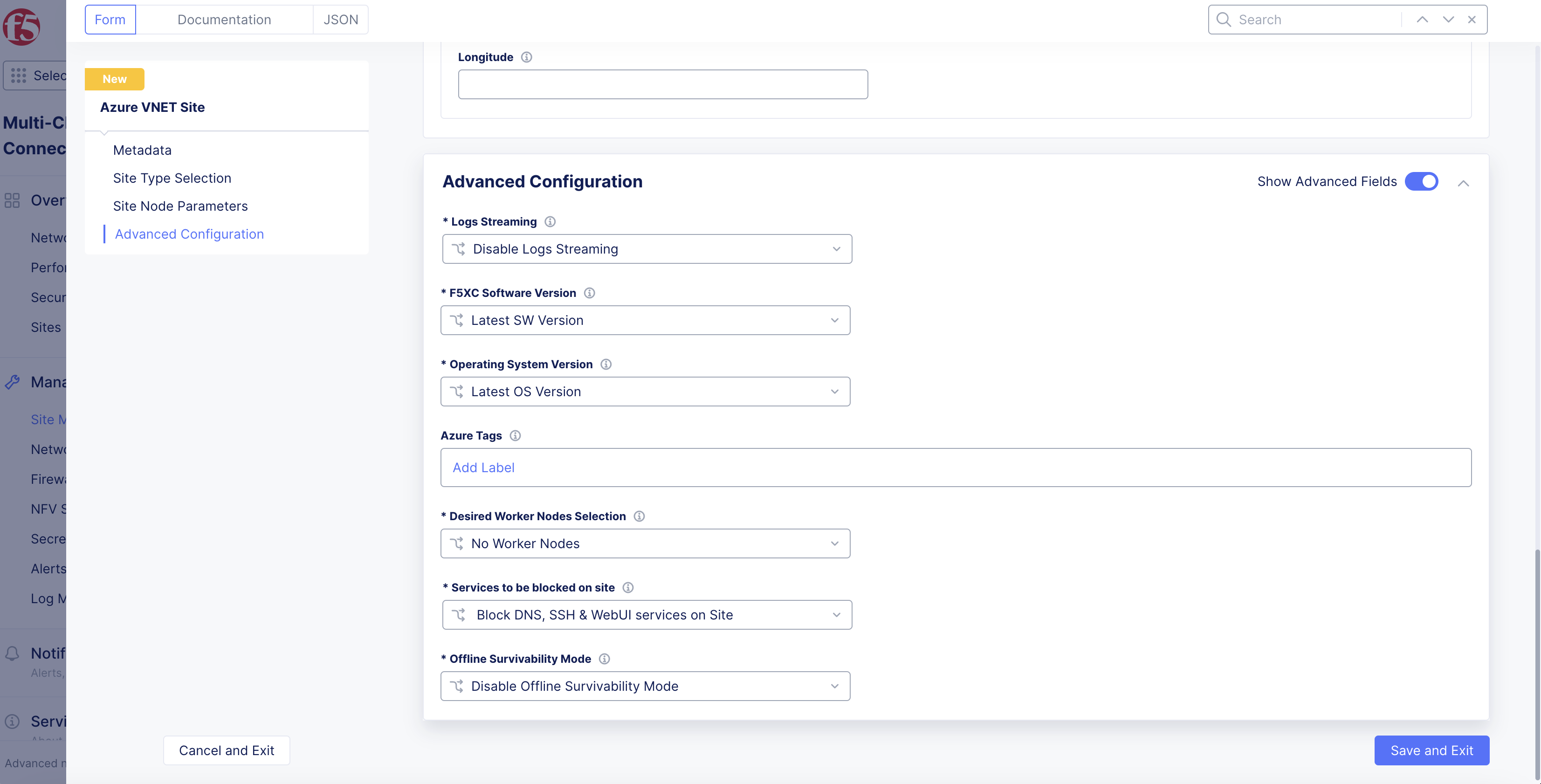
Figure: Site Advanced Configuration
Step 7.1: Configure blocked services from site.
-
From the
Services to be blocked on sitemenu, selectCustom Blocked Services Configuration. If you selectAllow access to DNS, SSH services on Site, no further configuration is needed. -
Click
Add Item. -
From the
Blocked Services Value Typemenu, select the service to block:-
DNS port -
SSH port
-
-
From the
Network Typemenu, select the type of network in which this service is blocked from your site. -
Click
Apply.
Step 7.2: Enable the offline survivability feature for your site.
From the Offline Survivability Mode menu, select Enable Offline Survivability Mode. This action will restart all pods for your site. For more information, see the Manage Site Offline Survivability guide.
Step 8: Complete the site object creation.
New VNet Site
Click Add Azure VNet Site to complete creating the site. The Status field for the site object displays Validation in progress. After validation, the field displays Validation Succeeded.
Existing VNet Site
If you used an existing VNet, Console will validate whether certain existing objects are available and valid. This provides current information to help troubleshoot and fix any potential issues without having to wait until the full site deployment process completes.
After you click Save Azure VNet Site, the validation process begins and is displayed as Validation in progress.
If the site deployment validation failed, a message with Validation Failed will be displayed. Click on the tooltip to display a popup message with the error.
If the site deployment validation succeeded, a message with Validation Succeeded will be displayed.
Note: The
QUEUEDstate references site status action that is in process. The site status will remain inQUEUEDstate until the backend service is ready to executeApply/Plan/Destroycommands. The site status (under theStatuscolumn) is updated on the Console once the execution begins. After a maximum duration of 15 minutes, the site will stay in theQUEUEDstate until the status times out after which a new state is set asPROVISION_TIMEOUT.
Deploy Site
Creating the Azure VNet object in Console generates the Terraform parameters.
Step 1: Deploy site.
-
Navigate to the Azure VNet object by clicking
Manage>Site Management>Azure VNET Sites. -
Find your Azure VNet object and click
Applyin theStatuscolumn. TheStatuscolumn for the site object changes first toQueuedand then toApplying.
Note: Optionally, you can perform Terraform plan activity before the deployment. Find your Azure VNet site object and select
...>Plan (Optional)to start the action of Terraform plan. This creates the execution plan for Terraform.
-
Wait for the status to change to
Applied. -
To check the status for the apply action, click
...>Terraform Parametersfor site object, and select theApply Statustab.
Step 2: Confirm site deployed and online.
-
Navigate to
Multi-Cloud Network Connect>Overview>Infrastructure>Sites. -
Verify status is
Online. It takes a few minutes for the site to deploy and status to change toOnline.
Note: When you update worker nodes for a site object, scaling happens automatically. You can use SSH to log in to your node with username
cloud-userand your private key.
Delete VNet Site
You have two options when deleting a site in Console. You delete the site entirely, with all its resources and configuration. Or you can simply delete the site, its resources, but maintain the existing configuration (so that it can be re-applied at a later time).
Note: Deleting the object deletes the sites, nodes, the VNet, and other objects created in the cloud for the site. This action also removes the site object from Console and cannot be undone.
Destroying a site deployed on an existing VNet will leave the subnets used for Site Local Outside, Site Local Inside, and Workload subnets without any explicit route associations.
Delete Site Completely
-
Navigate to
Manage>Site Management>Azure VNET Sites. -
Locate the site object.
-
Select
...>Delete. -
Click
Deletein pop-up confirmation window. In case the delete operation does not remove the object and returns any error, check the error from the status, fix the error, and re-attempt the delete operation. If the problem persists, contact technical support. You can check the status using the...>Terraform Parameters>Apply statusoption.
Delete Site but Maintain Configuration
-
Navigate to
Manage>Site Management>Azure VNET Sites. -
Locate the site object.
-
Click
Destroyfor your site. Alternately, click...>Destroy. -
In the pop-up window, type
DELETE. -
Click
Destroyto confirm the action. On successful operation, the site status will showDestroyedand theApplybutton will appear on the row of your site. This can be used to create the site again at later time, if required. The site object is no longer required and can be removed from Console by clickingDeletein theActionsmenu for the site.
Deploy Using Terraform
This chapter provides instructions on how to create a single-node or multi-node site on Microsoft Azure with Terraform.
Perform the following procedure to deploy a site using Terraform:
Step 1: Confirm Terraform is installed.
In a terminal, enter terraform version. If you need to install, follow the instructions at the official guide.
Step 2: Create API credentials file.
Log into Console and create an API 12 certificate file and then download it. Use the instructions at Credentials for more help.
Step 3: Create a new directory on your system to place files for deployment.
Create a new directory on your system to place files for deployment.
Step 4: Create the deployment file.
-
Create a file and name it
main.tffile, and place it in the newly created directory. -
Copy and paste the following information into the file:
terraform { required_version = ">= 0.13.1" required_providers { volterra = { source = "volterraedge/volterra" } }}variable "site_name" {}variable "az_client_id" {}variable "az_subscription_id" {}variable "az_tenant_id" {}variable "b64_az_client_secret" {}variable "az_region" { default = "westus2"}variable "az_vnet_cidr" { default = "192.168.0.0/20"}variable "outside_subnet_cidr_block" { default = "192.168.0.0/25"}resource "volterra_cloud_credentials" "azure_cred" { name = format("%s-cred", var.site_name) namespace = "system" azure_client_secret { client_id = var.az_client_id subscription_id = var.az_subscription_id tenant_id = var.az_tenant_id client_secret { clear_secret_info { url = format("string:///%s", var.b64_az_client_secret) } } }}resource "volterra_azure_vnet_site" "site" { name = var.site_name namespace = "system" azure_region = var.az_region ssh_key = "ssh-rsa XXXX" resource_group = var.site_name azure_cred { name = volterra_cloud_credentials.azure_cred.name } vnet { new_vnet { name = var.site_name primary_ipv4 = var.az_vnet_cidr } } disk_size = 80 machine_type = "Standard_D8_v4" ingress_gw { azure_certified_hw = "azure-byol-voltmesh" az_nodes { azure_az = "1" disk_size = 100 local_subnet { subnet_param { ipv4 = var.outside_subnet_cidr_block } } } } lifecycle { ignore_changes = [labels] }}resource "volterra_tf_params_action" "apply_azure_vnet" { site_name = volterra_azure_vnet_site.site.name site_kind = "azure_vnet_site" action = "apply" wait_for_action = true ignore_on_update = true}-
Open the file and configure any necessary fields. You can change the parameters for your particular setup.
-
Save the changes and then close the file.
Step 5: Create file for variables.
-
In the same directory, create another file for variables and name it
terraform.tfvars. -
Create and assign the following variables:
-
For your site name, type a name within double quotes:
site_name = "<site-name>" -
For the region, type the name within double quotes:
az_region = "<az-region-which-supports-availability-zone>" -
For the client ID, type the name within double quotes:
az_client_id = "<az-client-id>" -
For the subscription ID, type the name within double quotes:
az_subscription_id = "<az-subscription-id>" -
For the tenant ID, type the name within double quotes:
az_tenant_id = "<az-tenant-id>"
-
site_name = <site-name>az_region = <az-region-which-supports-availability-zone>az_client_id = <az-client-id>az_subscription_id = <az-subscription-id>az_tenant_id = <az-tenant-id>Step 6: Create and export variables for credentials and secret keys.
-
In the terminal, create and export the following variables:
-
Create this variable and assign it the value of the Base64 encoded client secret:
export TF_VAR_b64_az_client_secret=<base64-encoded-secret> -
Create this variable and assign it the URL for your tenant. For example:
export VOLT_API_URL=https://example.console.ves.volterra.io/api -
Create this variable and assign it the path to the API credential file previously created and downloaded from Console:
export VOLT_API_P12_FILE=<path-to-local-p12-file> -
Create this variable and assign it your API credentials password:
export VES_P12_PASSWORD=<credential-password>
-
Note: You can also create and save these variables in the
terraform.tfvarsfile. However, this may pose a security risk. Use caution when working with your credentials and secret keys.
export TF_VAR_b64_az_client_secret=<base64-encoded-secret>export VOLT_API_URL="https://<tenant>.console.ves.volterra.io/api"export VOLT_API_P12_FILE=<path-to-credential-p12-file>export VES_P12_PASSWORD=<password-for-credential-p12-file>Step 7: Initiate Terraform process.
Enter terraform init.
Step 8: Apply Terraform process.
-
Enter
terraform apply. -
If prompted for the access key and secret key encoded in Base64, enter both.
-
Enter
yesto confirm. This may take a few minutes to complete. After the process is complete, the output will stateApply complete!. -
In Console, navigate to the list of sites and confirm the site was applied.
Destroy Site
Perform the following procedure to destroy the site using Terraform:
-
Enter
terraform destroy. -
If prompted for the access key and secret key encoded in Base64, enter both.
-
Enter
yesto confirm. This may take a few minutes to complete. After the process is complete, the output will stateDestroy complete!. -
In Console, navigate to the list of sites and confirm the site was destroyed.
Next Steps
After you have successfully deployed your site, you can choose to upgrade it or create a site mesh group (SMG).
- To update your site to the latest OS version, click
Upgradeunder theSoftware Versiontile on the dashboard.
Note: Site upgrades may take up to 10 minutes per site node. Once site upgrade has completed, you must apply the Terraform parameters to site via
Actionmenu on cloud site management page.
Figure: Site OS Upgrade
- To create an SMG, see the Site Mesh Group guide for more information.
Concepts
API References
On this page:
- Objective
- Azure VNet Site Design Overview
- Deployment Environments
- Customer Edge Node Clustering
- Azure VNet Site Deployment Modes
- Ingress Gateway (One Interface)
- Ingress/Egress Gateway (Two Interfaces)
- Network Policies
- Forward Proxy Policy
- Site Status Descriptions
- Prerequisites
- Deploy Using Console
- Accept Subscription Agreement
- Create Azure VNet Site Object
- Deploy Site
- Delete VNet Site
- Deploy Using Terraform
- Destroy Site
- Next Steps
- Concepts
- API References