Create NAT Policy
Objective
This guide provides instructions on how to create a Network Address Translation (NAT) policy using the guided wizard in F5® Distributed Cloud Console (Console).
Prerequisites
-
F5 Distributed Cloud Services account. If you do not have an account, see Getting Started with Console.
-
Ensure that your CE Site is running the December 10, 2024, release or later.
Overview
Network Address Translation (NAT) maps addresses from one address space to another. One such use case would be to NAT private addresses to public addresses for Internet access where other cases could involve overlapping addresses as a result of a merger or acquisition. This document references the NAT on Customer Edge (CE) capabilities and use cases.
The default behavior of a CE when no NAT policies are configured is to source NAT all packets from workloads behind it, including those in segments allowed Internet access by the administrator, to the CE's Site Local Outside (SLO) address.
Use Cases
NAT support on the Customer Edge (CE) addresses three primary use cases:
Overlapping Addresses: This common challenge often arises due to mergers and acquisitions, poor network planning, or lack of coordination between different teams.
In the figure below, you can see VPC-PROD and VPC-SHARED have a common CIDR of 10.1.0.0/16; however, any other form of overlap can also be addressed within our NAT functionality.
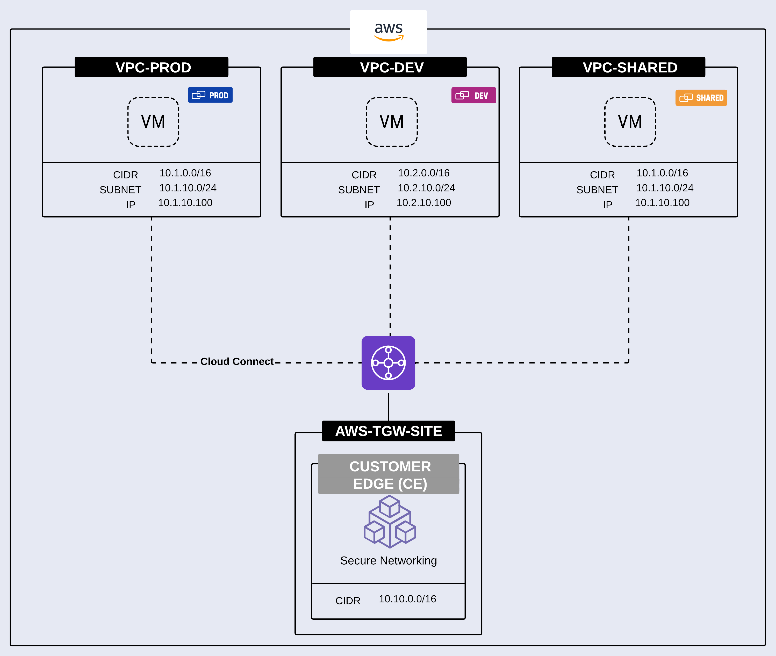
Figure: Solving Overlapping Addresses with NAT
Masking the real addresses of hosts: In some cases, you may need to mask the real address of specific hosts or an entire network when communicating with external or third-party entities. This is not typically due to overlapping addresses. You can achieve this using Source NAT with a SNAT Pool. The example below shows the Subnet 10.1.100.0/24 being translated via Source NAT to 192.168.100.0/24.
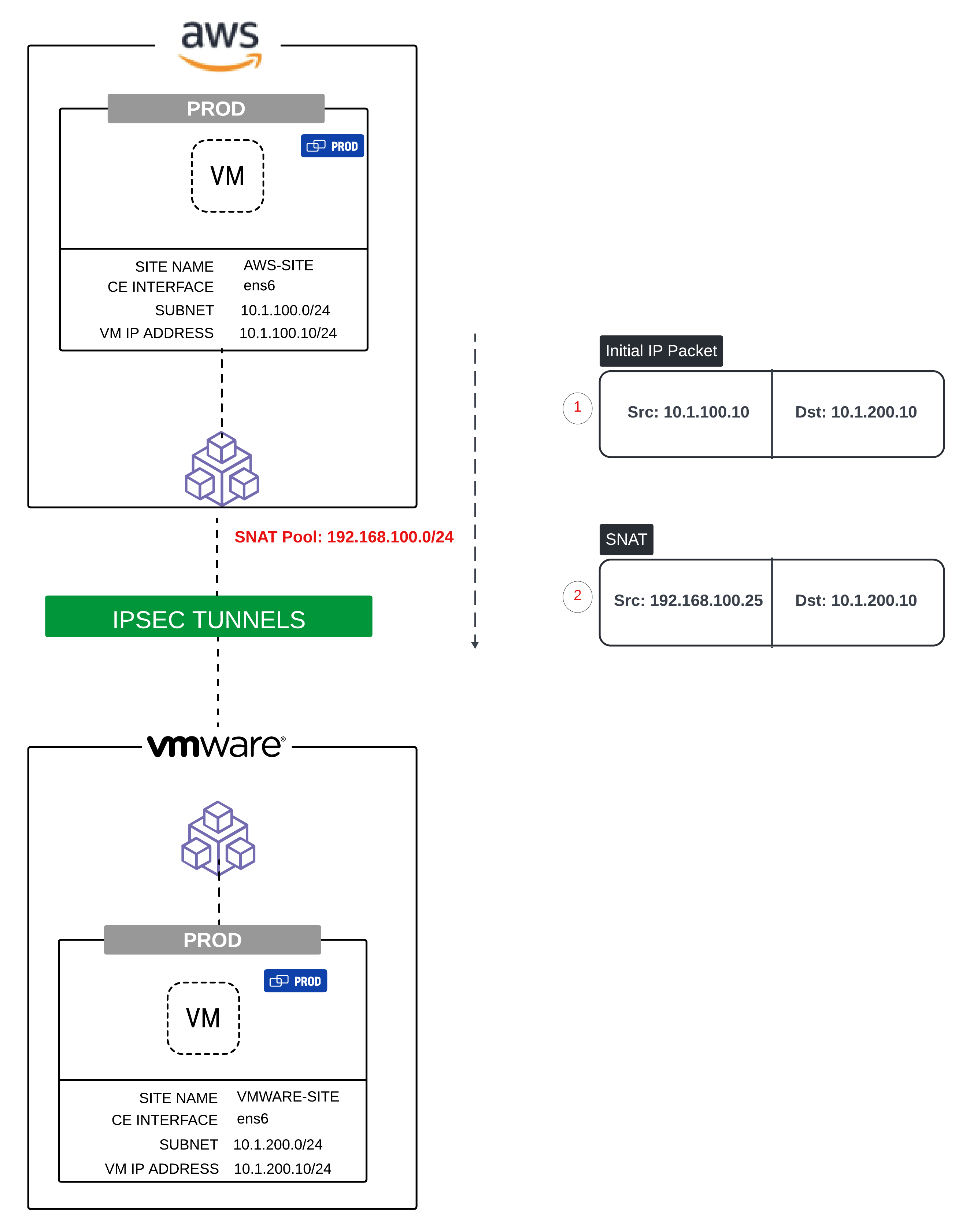
Figure: Masking the real address of hosts with NAT
SNAT for Internet Access: If no NAT policies are configured, the default behavior of the CE is to Source NAT all workloads behind it, including those in segments allowed Internet access by the administrator, to the CE's Site Local Outside (SLO) address. However, you might want a specific workload, VPC, or subnet to egress with one or more particular public IP addresses. The example below shows three VPCs (VPC-PROD, VPC-DEV, and VPC-SHARED) each being source NAT to a specific Elastic IP Address (Public IP Address).
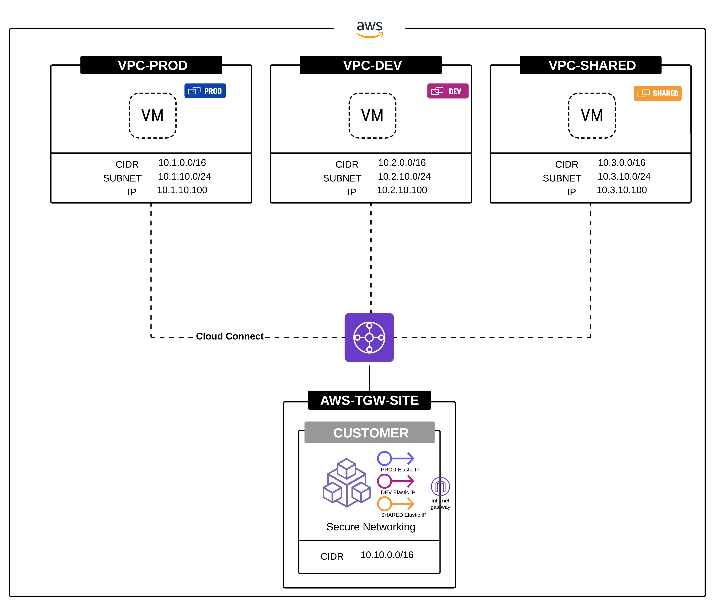
Figure: Internet Access with Address-Specific NAT
Configuration
Create a NAT Policy
A NAT Policy is composed of rules, and the order in which the rules are configured would dictate which rule would take precedence.
Step 1: Navigate to the NAT Policies page.
-
Log into Console.
-
Click
Multi-Cloud Network Connect.
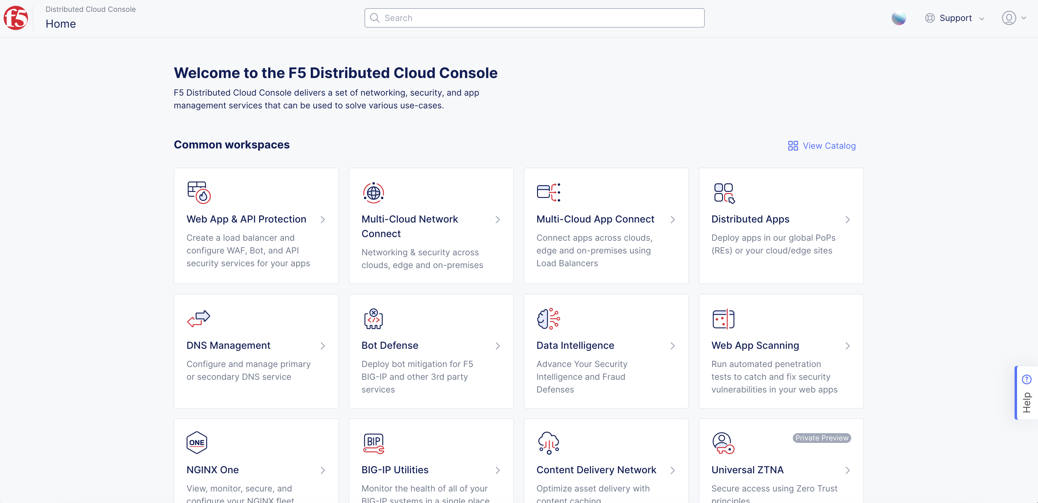
Figure: Console Homepage
- Select
Manage>Networking>NAT Policies.
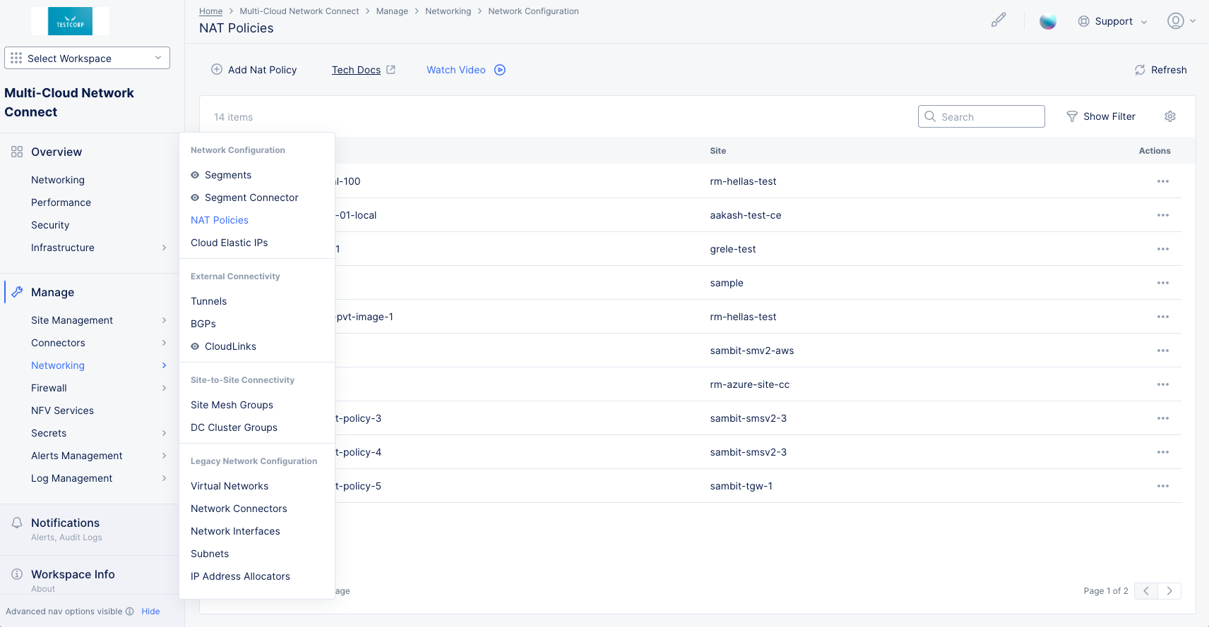
Figure: NAT Policies
Step 2: Start creating a NAT policy.
- Click
Add NAT Policy.
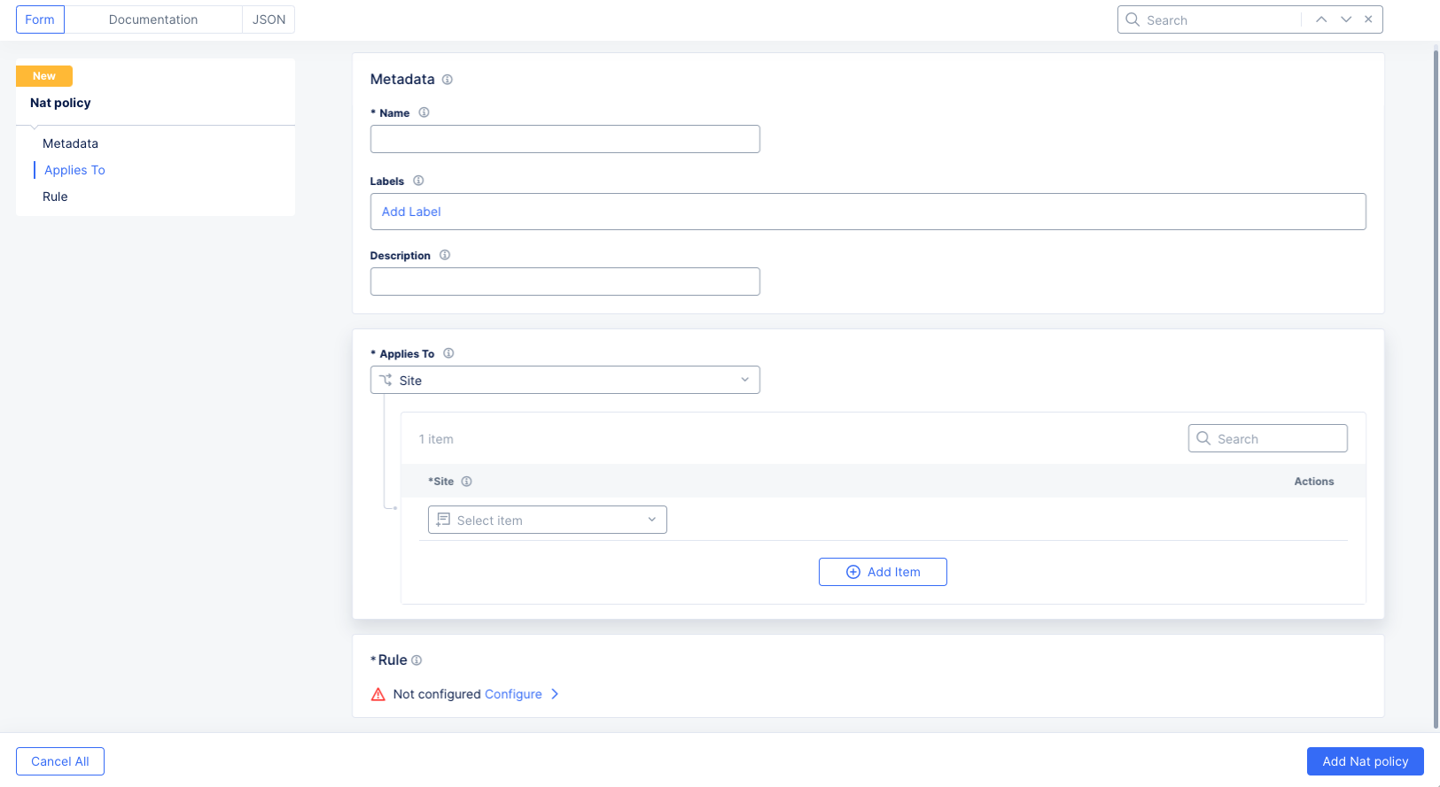
Figure: NAT Policy Form
-
In the
Namefield, enter the name for the new NAT policy. Optionally add labels and a description. -
In the
Applies Tosection,Siteis automatically selected since it is the only current option.- Select a site from the
Sitedrop-down menu for which the NAT Policy is being applied. - You can have the policy apply to multiple sites by clicking the
Add Itembutton in the sites list. NAT Policies are supported for multiple sites simultaneously.
- Select a site from the
Step 3: Create NAT Policy Rules.
-
In the
Rulesection on theNAT Policyform, clickConfigureto create a list of rules. -
Click
Add Itemto create the first rule.

Figure: NAT Policy Rule Form
-
In the
Namefield, enter the name for the new NAT policy. Optionally add labels and a description. -
Select
YesorNofrom theEnabledrop-down menu to turn this rule on or off. Generally, rules are always enabled except when testing/troubleshooting or in situations where you might plan for NAT configurations to only be applied during maintenance windows. -
In the
Scopesection, select the ingress point at which to apply the rule:Cloud Connect: Cloud Connects instantiate a GRE Tunnel on the CE that connects to the TGW. Thus, by selecting the Cloud Connect you are expecting the traffic to arrive on the particular GRE Tunnel from the TGW. You can select one Cloud Connect at a time.Interface: Select an Ethernet interfaces that is available on the CE. You can select one interface at a time. The NAT rule will apply to the packet coming from that interface.Segment: This is useful in situations where the interesting traffic can arrive at multiple interfaces in the same segment. Thus, instead of selecting a single interface and repeating the NAT rules, you can select a segment and the result is that the rule is applied to all interfaces that belong to that segment. Do not selectSegmentfor your scope if yourActionis set toVirtual Subnet NAT.Virtual Network: Prior to Segmentation, Global Networks were the main construct to place different sites in the same VRF. Thus, this option is meant to apply NAT on those legacy site types that utilize virtual networks. The NAT rule will apply to the packet in the virtual network. Do not selectVirtual Networkfor your scope if yourActionis set toVirtual Subnet NAT.
-
The
Match Criteriasection allows you to specify which packets should go through NAT processing.
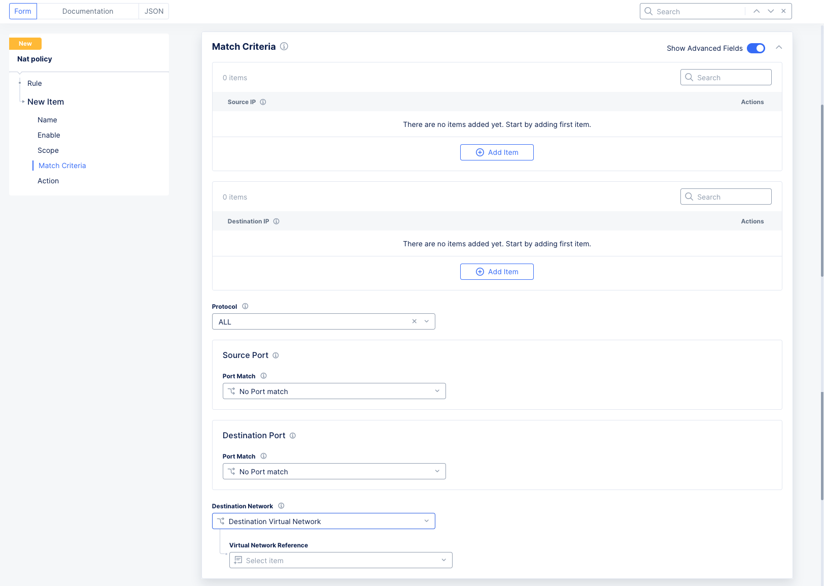
Figure: NAT Policy Rule Form
-
Standard options:
Source IP: ClickAdd Itemand enter an IP prefix for each source IP you want included.Destination IP: ClickAdd Itemand enter an IP prefix for each destination IP you want included.
Note: If a NAT policy is being applied on a given site, only one rule can have both Source and Destination Prefix Match in the Match criteria. The other rules must have only Source Prefix Match.
- Advanced options (enable the
Show Advanced Fieldstoggle):
Note: These advanced match options are not supported for the case of overlapping CIDRs where the NAT Action is set to
Virtual Subnet NAT.
Protocol: Select a protocol to match from the drop-down list. OnlyAllor a single protocol can be selected.Source Port: SelectPortorPort Rangeto match specific port(s). The default isNo Port match.Destination Port: SelectPortorPort Rangeto match specific port(s). The default isNo Port match.Destination Network: If there is a network connector, selectDestination Virtual Networkand then select theVirtual Network Reference. If there is a segment connector, selectDestination Segmentand then select theSegment. If there is neither, thenDestination Networkdoes not need to be configured.- The
Destination Networkoption will only be used when the traffic is destined to:- Internet: This is egress traffic from networks behind the CE to the Internet. In this case the destination network will be set to Virtual Network, and you specify the SLO network. This is the most common usage for the destination network.
- SLI: This is only used when the traffic is destined to the Site Local Inside (SLI) network.
- The
Note: In this release, these virtual networks need to be created to be able to reference them, thus you will need to navigate to
Manage>Networking>Virtual Networkand then add aVirtual Networkof typeSite Local Outside or Site Local Inside. With the virtual network for SLO or SLI created, then you can reference those in the NAT configuration.
- Configure the
Actionsection to specify what happens when the match criteria above are satisfied (a match occurs).
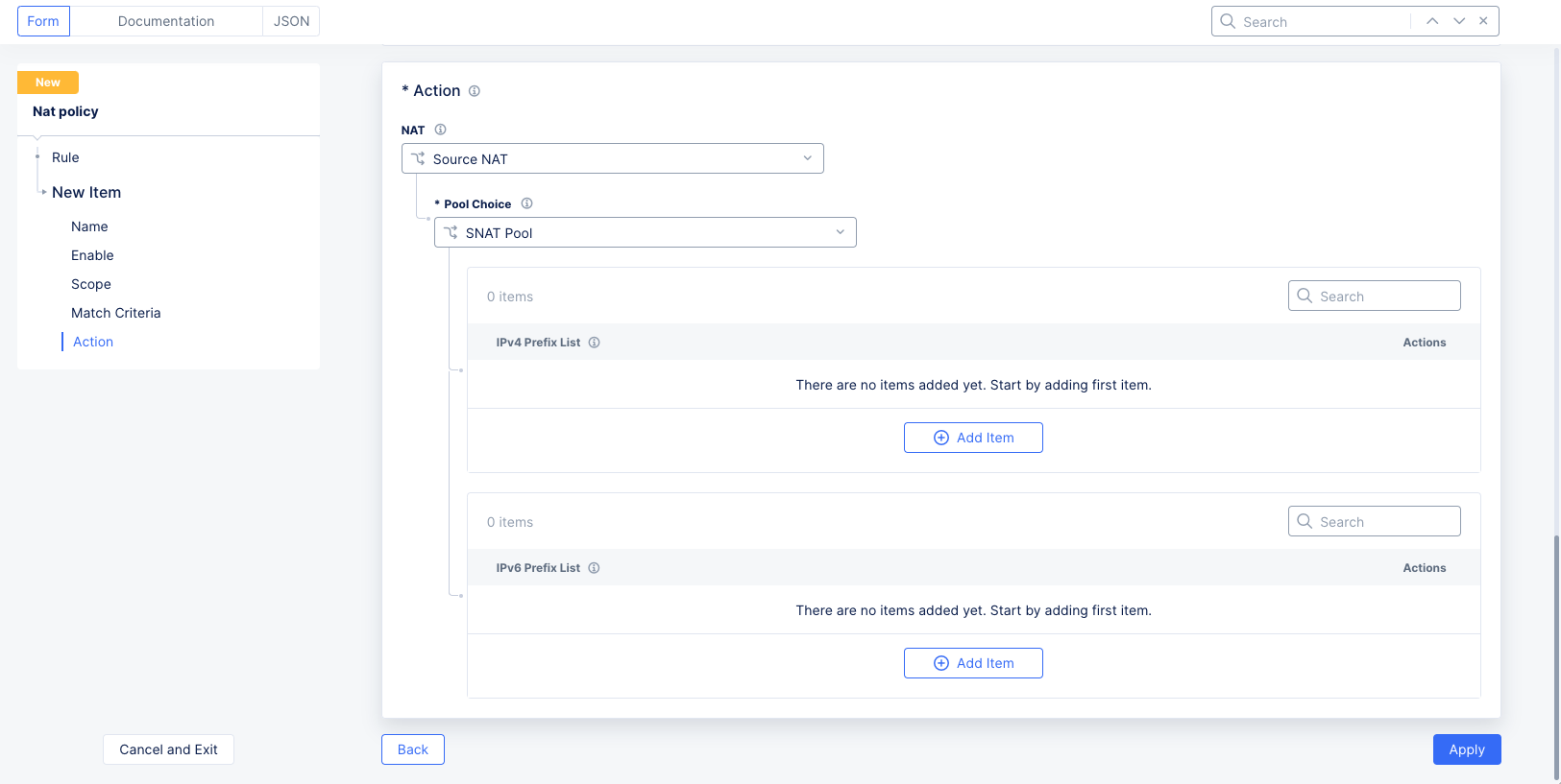
Figure: NAT Policy Rule Form
-
In the
NATfield, select the type of action you want to take:-
Virtual Subnet Nat: Enter the virtual subnet NAT CIDR. Virtual Subnet NAT is static NAT that does a one-to-one translation between the real source IP CIDR in the policy and the virtual CIDR in a bidirectional fashion. The range of the real CIDR and virtual CIDRs should be the same (e.g. if the real CIDR has the CIDR 10.10.10.0/24, the virtual CIDR has 100.100.100.0/24). This is the best option for overlapping CIDRs. One key advantage ofVirtual Subnet NATis that it preserves the host bit during translation, making it easier to identify the original hosts in the flow. For instance, if the original subnet is 10.10.10.0/24 and it is translated to 100.100.100.0/24, a host with the address 10.10.10.5 will be translated to 100.100.100.5, preserving the .5 host bit. Additionally, the CE advertises these virtual subnets to other CEs and third-party devices to ensure return traffic is correctly routed to the corresponding nodes. -
Source Nat: Use this to translate the source address of the matching packet (for example, when you want to mask the real IP address of a particular host or network). Note that with Source NAT, traffic can only be initiated from the host or networks that are being Source NAT and not from the remote networks since Source NAT is unidirectional in nature. Select the type of pool you want to use:-
SNAT Pool: Use theAdd Itembuttons to enter the pool members in either IPv4 or IPv6 format. These pools can reference a single /32 address or be much larger. Note that for a 3-node site, the pool must contain at least 3 addresses to ensure each node has an IP address from the pool for Source address translation. For larger pools, such as /24, the CE automatically allocates subsets to multiple nodes without user intervention. Additionally, CE nodes ensure these per-node subnets are advertised to other CEs and third-party devices to route return traffic correctly. For IPv6, this functionality must be enabled for the Tenant. -
Cloud Elastic IP Object: Use theAdd Itembuttons to enter one or more cloud elastic IP references. This is useful for example when you want a particular workload, VPC, subnet, or Cloud Connect to egress with one or more specific public IP addresses. See Create a Cloud Elastic IP to create a new one.
-
-
-
Click
Applyto save the rule. -
Click
Add Itemin theRulelist to add more rules.
Note: When viewing the list of rules for your NAT Policy, you can reorder your rules by dragging the 6-dot handle (to the left of the rule) to a new position.
- Click
Applywhen finished adding rules to the list.
Step 4: Finish creating a NAT Policy.
Click Save and Exit to create the NAT policy.
Create a Cloud Elastic IP
A Cloud Elastic IP object is associated to a CE Site and can contain 1 or more Elastic IP addresses depending on the configuration.
Step 1: Navigate to the Cloud Elastic IPs page.
-
Log into Console.
-
Click
Multi-Cloud Network Connect.

Figure: Console Homepage
- Select
Manage>Networking>Cloud Elastic IPs.
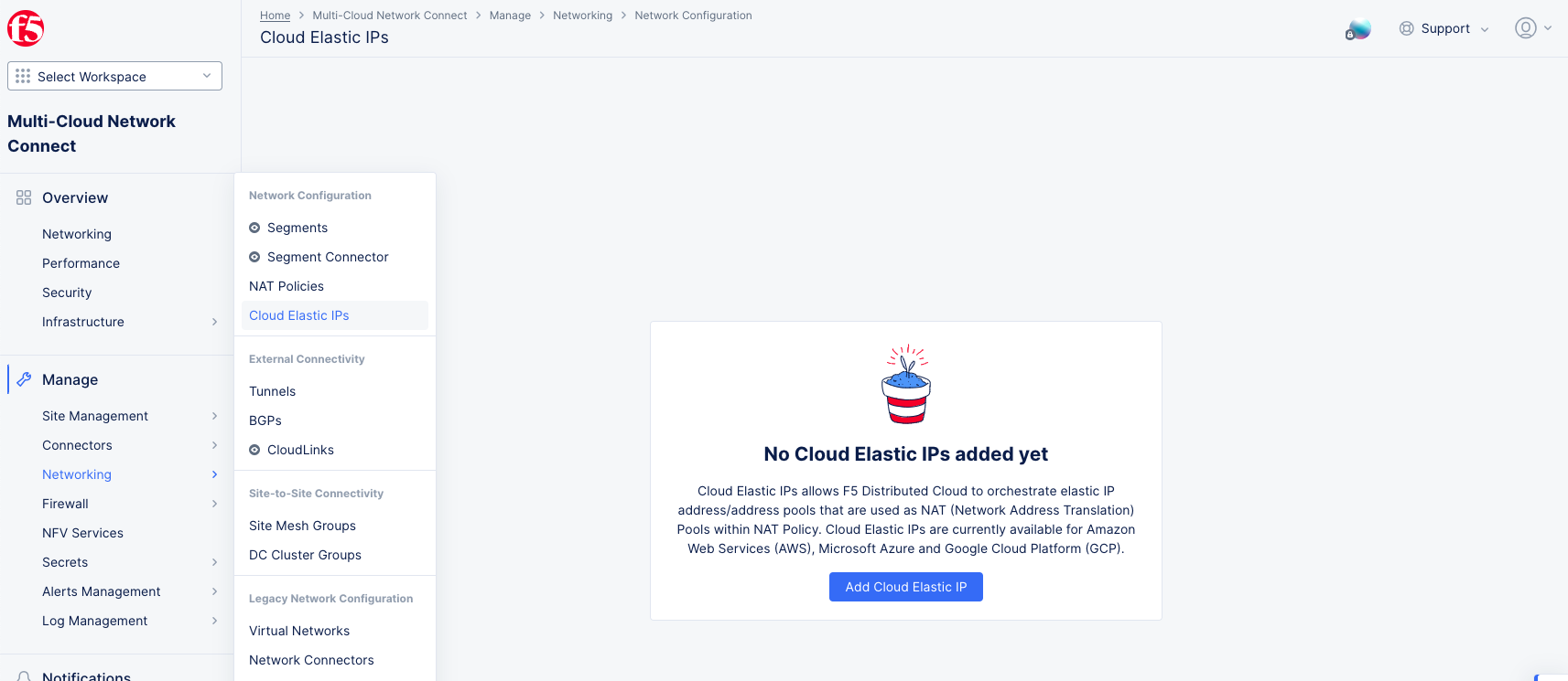
Figure: Cloud Elastic IPs
Step 2: Create a Cloud Elastic IP.
- Click
Add Cloud Elastic IP.
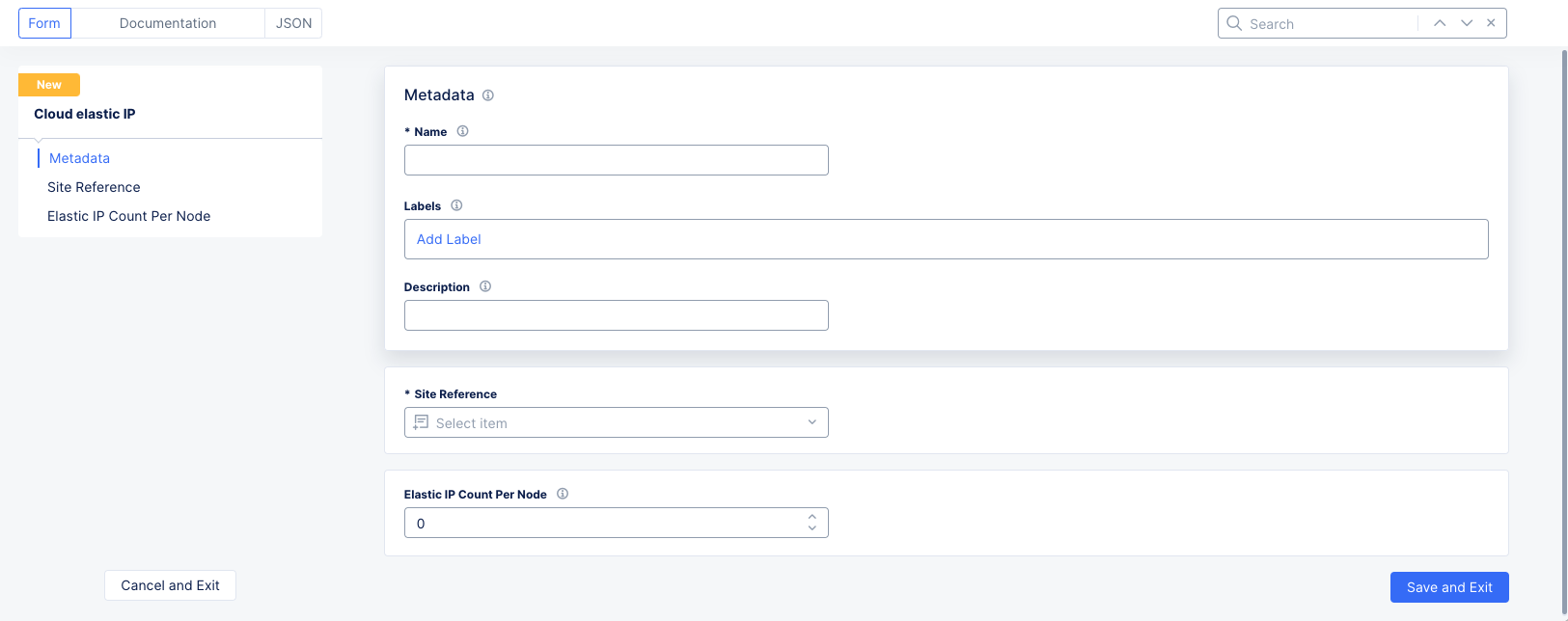
Figure: Cloud Elastic IP Form
-
In the
Namefield, enter the name for the new Cloud Elastic IP object. Optionally add labels and a description. -
Select a site from the
Site Referencedrop-down menu that will have the elastic IP(s). -
In the
Elastic IP Count Per Nodefield, enter the number of required elastic IPs per node. -
Click
Save and Exit.
Example Scenario - Overlapping Addresses
In this particular example, VPC-PROD belongs to the PROD Segment, VPC-SHARED belongs to the SHARED Segment, and a segment connector of type Direct is configured between them. Refer to Segment Connectors for more information. It is evident in this scenario that both VPC-PROD and VPC-SHARED have an overlapping CIDR of 10.1.0.0/16.

Figure: NAT Policies use case 1
In order to solve this, virtual subnets (Static NAT) will be used to map each VPC with overlapping CIDRs to a virtual subnet. When this is done, you need to define the native network, which is the network that will communicate using its real address (10.1.0.0/16) and will be only translated when it communicates to the other network with the overlapping address. All other communications from the native network will not be translated. The non-native network, on the other hand, will always be masked. This ensures that when a packet is destined to 10.1.0.0/16, there is a single destination to which to forward the packet.
VPC-PROD will be configured to be the native network. In other words, it will only be translated when it talks to VPC-SHARED. All other communications from VPC-PROD continue to use the native or real address. VPC-SHARED on the other hand will always be masked.
Virtual subnet for VPC-PROD is 100.100.0.0/16.
Virtual subnet for VPC-SHARED is 100.101.0.0/16.
Because the overlap is happening between two Cloud Connects, a Cloud Connect Scope is used. Since this rule is for the vpc-prod-nat-rule for VPC-PROD, then you will choose the Cloud Connect that is mapped to VPC-PROD (as in prod-connector).
The rules for each of these policies would be configured as follows:
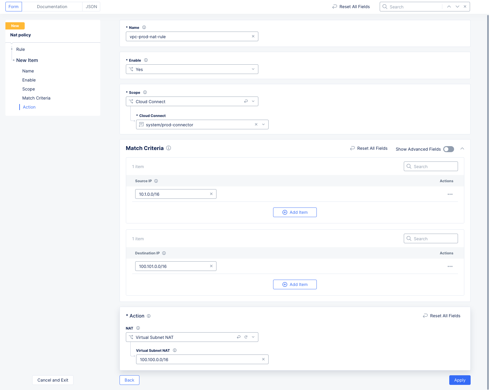
Figure: VPC-PROD NAT Policy Rule Configuration
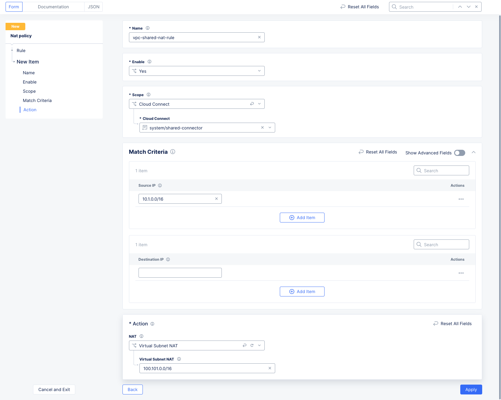
Figure: VPC-SHARED NAT Policy Rule Configuration
Note that the Destination IP address for VPC-SHARED is blank, which means any destination.