Create External Connectors
Objective
The External Connector on the Customer Edge (CE) allows standard IPsec connectivity to third-party devices, such as routers and firewalls.
Note that IPsec supports both Tunnel Mode and Transport Mode. In Tunnel Mode, the entire inner IP packet, including both its IP header and payload, is encrypted and encapsulated within a new outer IP packet. In Transport Mode, only the payload of the inner packet is encrypted, while the original IP header remains intact and unencrypted. Currently, only Tunnel Mode is supported.
The figure below shows the topology with a three-node CE site, where each node within the site has a tunnel toward the router, bringing a total of three IPsec tunnels from the site to the external device. Note that the number of nodes that terminate the tunnel is configurable. For example, you can have a three-node site where only two nodes terminate the IPsec tunnel from the router.

Figure: Three-Node CE Site
Prerequisites
-
F5 Distributed Cloud Services account. If you do not have an account, see Getting Started with Console.
-
This is a CE only feature and has been verified to work with Mesh persona (not App Stack) for Orchestrated Sites (AWS VPC Site, AWS TGW Site, Azure VNET, GCP Site) in addition to manually deployed Secure Mesh Site v1 and Secure Mesh Site v2.
-
External Connectors are supported on Customer Edges running version crt-20250701-0198 or later.
High Level Configuration Steps
To configure an external connector successfully, it's crucial to understand that setting up an IPsec connection between the CE and the external device requires coordinated configuration on both ends. Specifically, the encryption, authentication, and key management algorithms must be compatible to ensure a successful tunnel establishment.
At a high level, the three configuration steps on the CE to configure an external connector to a third-party device are as follows:
-
Configure IKE Phase 1 Profile or use an existing profile. There is a default profile to simplify the configuration steps while still providing the highest security standards.
-
Configure IKE Phase 2 Profile or use an existing profile. There is a default profile to simplify the configuration steps while still providing the highest security standards.
-
Configure the External Connector whereby at a high level you will:
-
Attach the IKE Phase 1 & Phase 2 Profiles
-
Specify the remote peer address for the CE to know its peer
-
Choose the nodes & underlay interfaces that will be part of this connection
-
Configure Tunnel Addresses
-
Pre-shared Keys for IKE Authentication
Configuration
Create an External Connector
The external connector configuration will instantiate the IPsec tunnel(s) toward the peer device. As discussed in the Objective section, for a three-node site, the tunnels can originate from one, two, or all three nodes toward the external router.
Step 1: Configure IKE Phase 1 Profile.
Default IKE Phase 1 profiles have been pre-created to simplify the configuration process. These profiles are designed to ensure the use of secure algorithms across authentication, encryption, and key management, while still providing multiple options within each category to support negotiation of the IKE Phase 1 Security Association with a peer. You can view all available default profiles by searching for “ves-io” in the search bar located at the top left.

Figure: Default IKE Profiles
In some cases, you might want to create your own profile and not rely on the pre-created profiles. This is where you can create your own IKE Phase 1 profile.
-
Log into Console.
-
Select the
Multi-Cloud Network Connectworkspace.
Figure: Console Homepage
- Select
Manage>Networking>IKE Profiles

Figure: IKE Profiles Page
-
Select the
Phase 1tab. -
Select
Add Phase 1 Profile.

Figure: IKE Phase 1 Profile Phase 1 Configuration
-
In the
Namefield, enter the name for the phase 1 profile that provides some relevance to its usage. Note that you can have a single profile across multiple connections. -
Optionally add labels and enter a description.
-
Select one or more encryption algorithms (the default is
AES256_GCM) using theConfigure Encryption Algorithmsdrop-down menu.
Note: This is an AEAD Algorithm (Authenticated Encryption with Associated Data) that combines encryption and authentication in one step, ensuring data confidentiality and integrity. If you select an AEAD algorithm, you shouldn't choose an authentication algorithm.
If you select a CBC (Cipher Block Chaining) encryption algorithm, you will need to select an authentication algorithm. Choosing more algorithms will help you find the Least Common Denominator (LCD) between the CE and the one or many peers it connects to.
- Select one or more authentication algorithms (the default is
No Authentication) using theAuthentication Algorithmsdrop-down menu.
Note: If you selected an AEAD algorithm, you can only choose
No Authentication. Choosing more algorithms will help you find the Least Common Denominator (LCD) between the CE and the one or many peers it connects to.
- Select one or more pseudo-random functions (the default is
PRFSHA512) using thePseudoRandomFunctiondrop-down menu.
Note: Your selection(s) will be used in IPsec to generate cryptographic keys from input data, such as a shared secret or session parameters. It ensures that the output keys are unpredictable and secure, providing the necessary keying material for encryption and authentication in the VPN. Choosing more algorithms will help you find the Least Common Denominator (LCD) between the CE and the one or many peers it connects to.
- Select one or more Diffie-Hellman groups (the default is
PRFSHA512) using theDiffie Hellman Groupsdrop-down menu.
Note: Diffie-Hellman groups refer to predefined sets of parameters used in the Diffie-Hellman key exchange to determine the strength and security of the shared secret generated between two parties during key exchange. The default selection is Group 19. Choosing more algorithms will help you find the Least Common Denominator (LCD) between the CE and the one or many peers it connects to.
-
Select a key lifetime duration from the
Key LifeTimedrop-down menu (the default isDefault (4 Hours)). This specifies the amount of time before the IKE Security Association needs to be renegotiated. If you selectMinutesorHours, then also enter the number of minutes or hours for the duration. -
Select a timeout duration using the
IKE Reauthenticationdrop-down menu. This is the amount of time for IKE peers to re-authenticate with one another. If you selectDaysorHours, then also enter the number of days or hours for the duration. -
Select
Add Phase 1 Profile.
Step 2: Configure IKE Phase 2 Profile.
Default IKE Phase 2 profiles have been pre-created to simplify the configuration process. These profiles are designed to ensure the use of secure algorithms across authentication, encryption, and key management, while still providing multiple options within each category to support negotiation of the IKE Phase 2 Security Association with a peer. You can view all available default profiles by searching for “ves-io” in the search bar located at the top left.
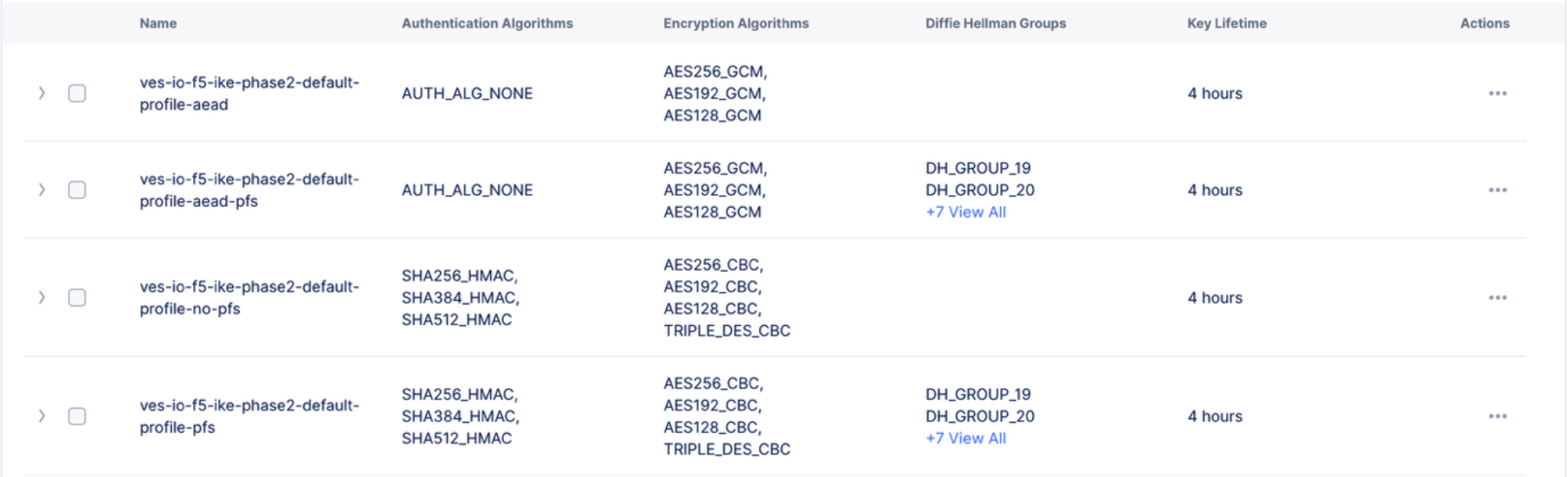
Figure: Default IKE Phase 2 Profiles
In some cases, you might want to create your own profile and not rely on the pre-created profiles. This is where you can create your own IKE Phase 2 profile.
-
Select the
Phase 2tab. -
Select
Add Phase 2 Profileon theIKE Profilespage.

Figure: IKE Phase 2 Profile Configuration
-
In the
Namefield, enter the name for the phase 2 profile that provides some relevance to its usage. Note that you can have a single profile across multiple connections. -
Optionally add labels and enter a description.
-
Select one or more encryption algorithms (the default is
AES256_GCM) using theConfigure Encryption Algorithmsdrop-down menu.
Note: This is an AEAD Algorithm (Authenticated Encryption with Associated Data) that combines encryption and authentication in one step, ensuring data confidentiality and integrity. If you select an AEAD algorithm, you shouldn't choose an authentication algorithm.
If you select a CBC (Cipher Block Chaining) encryption algorithm, you will need to select an authentication algorithm. Choosing more algorithms will help you find a Least Common Denominator (LCD) between the CE and the one or many peers it connects to.
- Select one or more authentication algorithms (the default is
No Authentication) using theAuthentication Algorithmsdrop-down menu.
Note: If you selected an AEAD algorithm, you can only choose
No Authentication. Choosing more algorithms will help you find the Least Common Denominator (LCD) between the CE and the one or many peers it connects to.
- Select
EnableorDisablefrom thePerfect Forward Secrecy (PFS)drop-down menu. Enabling PFS ensures that the encryption keys used in a session are not derived from the Diffie-Hellman (DH) process that happened in phase 1. If enabled, choose the appropriate DH Group(s) (the default isDH Group 19).
Note: PFS often requires an additional Diffie-Hellman (DH) exchange during Phase 2 of the IKE process. Choosing more algorithms will help you find the Least Common Denominator (LCD) between the CE and the one or many peers it connects to.
-
Select a key lifetime duration from the
Key LifeTimedrop-down menu (the default isDefault (4 Hours)). This specifies the amount of time before the IKE Security Association needs to be renegotiated. If you selectMinutesorHours, then also enter the number of minutes or hours for the duration. -
Select
Add Phase 1 Profile.
Step 3: Configure the External Connector
The external connector configuration instantiates the IPsec tunnel(s) towards the peer device. As noted in the Objective section, a three-node site can be configured with tunnels originating from one, two, or all three nodes toward the external router.
- Select
Manage>Networking>External Connectors.
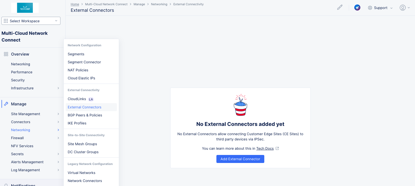
Figure: External Connectors
- Select
Add External Connector.

Figure: External Connectors - Metadata
-
Enter a name for the external connector that is relevant, as it describes a connection to a third party. For instance, if the remote peer device depicts branch 1 and you are connecting from ce-1, you can call it ce-1-branch-1-connection. The objective is to identify from the name the exact usage of this external connector.
-
Optionally, add labels and a description for more context.
-
Select a CE site from the
CE Site Referencedrop-down menu that is to connect to the external CE. Only one site can be selected. -
In the
Connection Detailssection, select the type of tunnel you want to create for your external connector. -
Select
IPsecfrom theConnection Typedrop-down menu. An IPsec (Internet Protocol Security) tunnel is a secure connection between two endpoints over an untrusted network, such as the internet. IPsec is a suite of protocols designed to provide secure, encrypted communication at the network layer. It ensures that data transmitted between the endpoints remains private, authenticated, and integrity protected.

Figure: External Connectors - Details
-
IKE Parameterssection:-
Select the profile you create in step 1 from the
IKE Phase 1 Profiledrop-down menu. -
Select the profile you create in step 2 from the
IKE Phase 2 Profiledrop-down menu. -
Select
InitiatororResponderin theModedrop-down menu. Initiator simply means that the CE will actively try to initiate connectivity to bring up the tunnel, whereas Responder means that the CE is in a waiting state and will only reply to connection attempts from the remote peer. -
Select
EnableorDisablein theDead Peer Detection (DPD)drop-down menu. DPD is a method to determine if the IPsec peer is still active and responsive. If you enable DPD, then enter a value in theKeepalive Timerfield. The keepalive timer specifies the frequency of the keep alive messages being sent (the default is 3 seconds). -
Local IKE ID: By default, this will be set to IP address of the interface that is used to source the tunnel, and this should suffice for most cases. There are some corner scenarios that involve NAT where using the default option will not work, and it will be best to resort to a hostname. The only requirement for Local IKE ID is that the peer should set the remote IKE ID to be identical to it. -
Remote IKE ID: By default, this will be set to IP address provided under the Remote Gateway IP address, and this should suffice for most cases. There are some corner scenarios that involve NAT where using the default option will not work, and it will be best to resort to a hostname. The only requirement for the remote IKE ID is that the peer should set its local IKE ID to be identical to it.
-
-
Tunnel Parameterssection:

Figure: External Connectors - Tunnel Parameters
-
In the
Remote Gateway IP Addresssection, enter the reachable IP address for the remote gateway. For instance, if the remote gateway is reachable over the public internet with a public address, then the remote Gateway IP Address would be the public address. -
In the
Tunnel Endpointsection, configure the participating CE nodes that will be part of this connection:-
Select
Add Item.
Figure: External Connectors - Tunnel Parameters
-
Select a
Nodefor this endpoint that will be part of this external connection. -
Select an
Interfacefor the node selected above. -
Enter both the local and remote tunnel IP addresses with their prefixes.
-
Select
Applyto save this node to the list of tunnel endpoints. -
If you want the tunnel to be sourced from multiple nodes, then select
Add Itemin theTunnel Endpointsection and repeat this process for each of the remaining nodes.
-
-
Enter your Pre-Shared Key (PSK) in the
Pre-Shared Keyfield. This PSK must match across the CE and the third-party device for proper establishment of the IPsec tunnel. -
In the
MTU (B)field, enter the maximum size (in bytes) of the packet that can be sent through the tunnel without the need to be fragmented. -
Use the
Segment/Networkdrop-down menu to selectSite Local Network (Outside),Site Local Network (Inside), orSegment. If you selectSegment, then also select a segment from theSegmentdrop-down menu.
Note: A tunnel interface can be assigned to one of the local networks: Site Local Outside, Site Local Inside, or it can be part of the configured segments. However, for configured segments, the underlying interface used as the tunnel source cannot be a segment.
- Select
Add External Connectorto save your external connector.
Supported Configurations for External Connectors
These are the supported combinations of underlay and overlay with the relevant notes where applicable.
| Underlay | Overlay | Supported Architecture | Notes |
|---|---|---|---|
| SLO | SLI | Yes | |
| SLO | Segment | Yes | |
| SLI | SLI | Yes | Ensure that a static route is configured in the SLI network for the IPsec VPN peer's destination IP, pointing to the correct next hop. Don't depend on the default route within the SLI Network. |
| SLI | Segment | Yes | Ensure that a static route is configured in the SLI network for the IPsec VPN peer's destination IP, pointing to the correct next hop. Don't depend on the default route within the SLI Network. |
| Segment | Segment | No |
Monitor an External Connector
There are two ways to monitor an external connector. The first way is to check the status of the external connector through its tunnels and/or its BGP Peers.
View an external connector's status.
-
Log into Console and select the
Multi-Cloud Network Connectworkspace. -
Navigate to
Manage>Networking>External Connectorsto see a list of your external connectors. -
Select the name of an external connector in the list to open up a side panel showing the status of the connection per node.

Figure: Monitor an External Connector
Note: A site can have three nodes, and one, two, or all three nodes can be tunnel endpoints i.e. participating in the connection towards the remote device. Assuming that the tunnels are sourced from all three nodes, the side panel will show the individual status of the individual connections from each of the nodes within the site to the third-party device, and each of those can be Up/Down.
In addition, if you are using BGP, the second tab on the side panel will show the BGP peering status in the same manner from each of the three nodes.
The second way is to monitor the connectivity on the site.
Monitor external connector on site.
-
Log into Console and select the
Multi-Cloud Network Connectworkspace. -
Navigate to
Overview>Infrastructure>Sitesto see a dashboard for all your sites. -
In the
Sitestable at the bottom, select the name of your site (optionally, enter a portion of the site name in theSearchfield to help find your site in the table). This will bring up the dashboard for your site. -
Scroll to the bottom of the page to see the
Connectivitytable and select theExternaltab to see all the external connections from the particular CE.

Figure: Monitor an External Connector
-
The Connection status can be one of three values: Up, Down, or Partially Up, where some but not all the connections from the nodes are up. Clicking on the connection status will show the state of the tunnels from each node.
-
Select the connection name to display the metrics of the connection in terms of the
In throughput,Out Throughput,In Drop RateandOut Drop Rate.
Additionally, you can run a packet capture on the external connector interface.
Run a packet capture.
Running a packet capture is a straightforward two-step process. First, identify the full interface name of the external connector you want to capture traffic on. Second, run the packet capture using that interface.
Get the full interface name:
- Select
Manage>Networking>External Connectors.
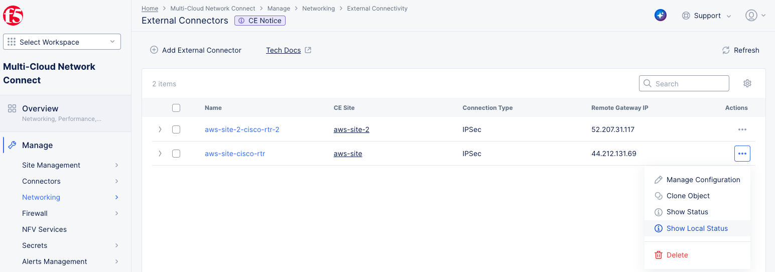
Figure: External Connectors - Get Local Status
- In the
Actionscolumn of the external connector of interest, select...>Show Local Status. This displays the local status.
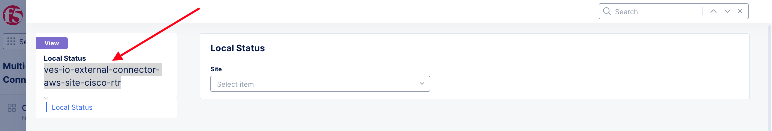
Figure: External Connectors - Local Status
- Copy the full name of the external connector and then select
Closeto close theLocal Statusview.
Run the packet capture:
- Next, select the site in the
CE Sitecolumn to bring up the site page showing theInfrastructuretab.
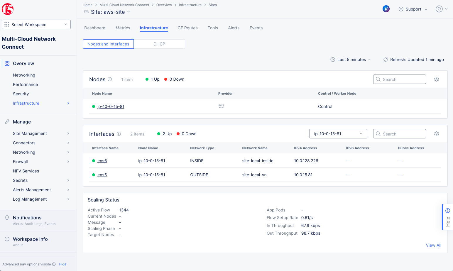
Figure: Site Infrastructure
-
Select the
Toolstab. -
Choose the
Tcpdumptool from theSelect Tooldrop-down menu. -
Select
New tcpdump.
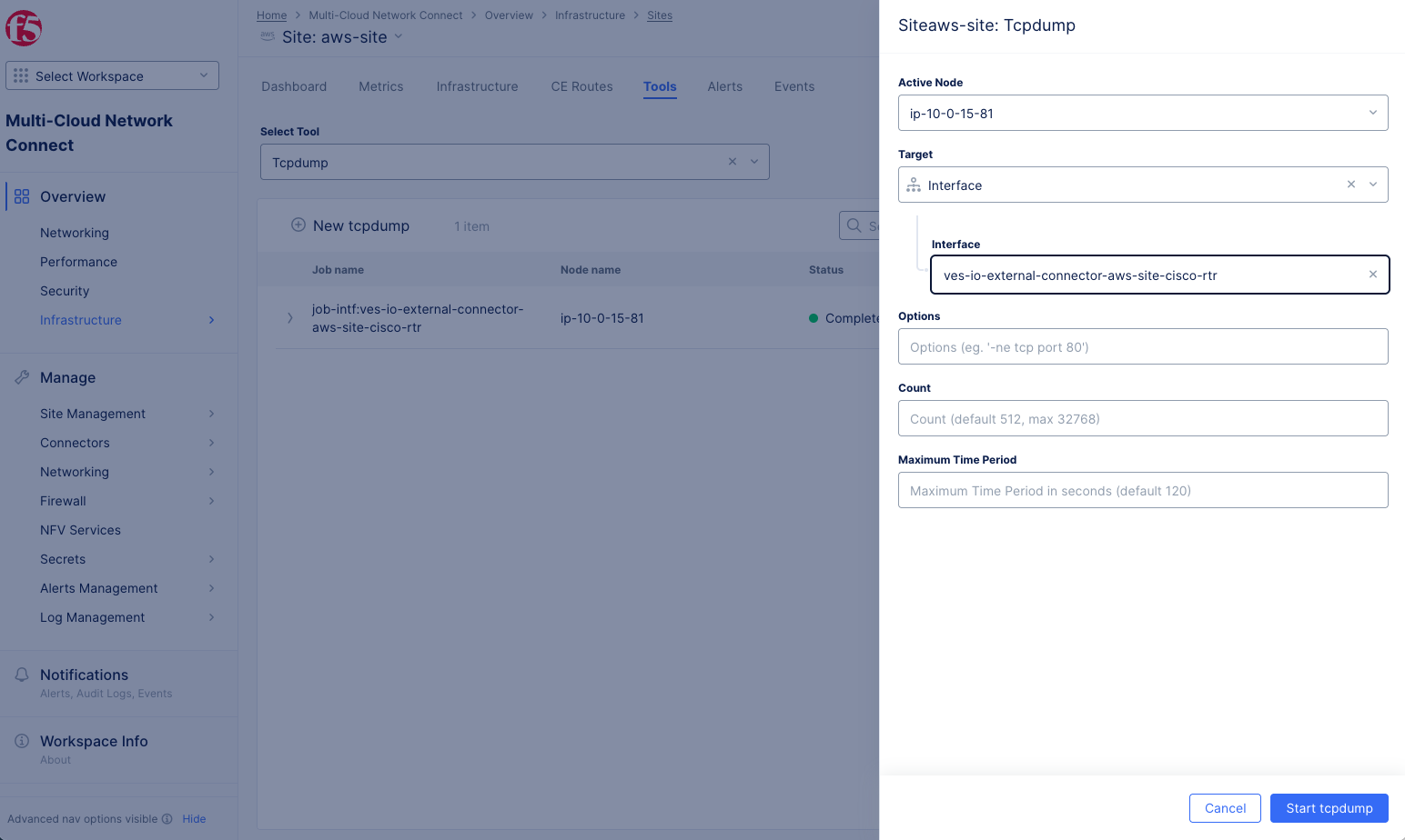
Figure: New Tcpdump
-
Select
Interfacefrom theTargetdrop-down menu. -
Paste the full name of your external connector into the
Interfacefield. -
Select
Start tcpdump. -
The
Statuscolumn will showRunningfollowed byCompleted. -
Once completed, select on
...>Fetchin theActioncolumn which will download the pcap file that can be opened using Wireshark.
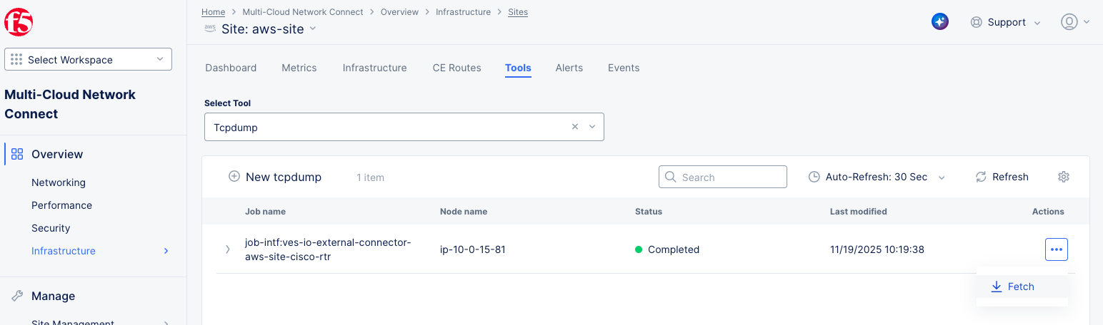
Figure: Fetch Tcpdump
Configure Routing
With the IPsec tunnel up and verified, you need to ensure end-to-end connectivity between the workloads behind third-party device and the workloads behind the CE depicted as Virtual Machines (VMs) in the diagram below. The diagram below has been simplified to focus primarily on the tunnel interfaces by removing the underlying details.
-
The CE site across its nodes knows how to reach 172.16.2.0/24 (subnet behind the third-party router) via the tunnel, and
-
The Router knows how to reach 172.16.1.0/24 (subnet behind CE site) via the tunnel.
This is possible either via BGP as the routing protocol of choice or via Static Routing. The diagram below shows BGP being used as the routing protocol.

Figure: External Connector Routing
For more information, see Configure BGP for Site.
Delete an External Connector
Perform the following steps to delete an External Connector:
Step 1: Navigate to the External Connectors page.
- Log into Console and select the
Multi-Cloud Network Connectworkspace.
Figure: Console Homepage
- Select
Manage>Networking>External Connectors.
Step 2: Delete an External Connector.
- Check the checkbox next to all external connectors you want to delete. Then, select
Delete Selectedabove the list.

Figure: Delete an External Connector
- Alternatively, select
...>Deletein theActionscolumn for the External Connector you want to delete.

Figure: Delete an External Connector
- Select
Deletein the confirmation pop-up window.
Delete an IKE Profile
Follow these steps to delete an IKE profile. Keep in mind that default, pre-created IKE profiles cannot be deleted. Additionally, before deleting an IKE profile, verify that it is not being used by any active IPsec connections.
Step 1: Navigate to the IKE Profiles page.
-
Log into Console.
-
Click
Multi-Cloud Network Connect.
Figure: Console Homepage
- Select
Manage>Networking>IKE Profiles
Figure: IKE Profiles Page
Step 2: Delete a profile.
-
Select the
Phase 1orPhase 2tab. -
Check the checkbox for the profile you wish to delete. You may select more than one profile to delete.
Note: You can narrow your search for profiles by entering a string in the
Searchfield at the top right of the table. The table will then only show lines that include what you entered.

Figure: Delete IKE Profiles
- Select
Delete selected.