Industrial Server 8000 series User Manual
Objective
This guide presents detailed information on the F5 Volterra Industrial Server (ISV) series 8000. The information includes instructions on physical installation of the ISV 8000 series devices and details on various operational components such as ports, interfaces, etc.
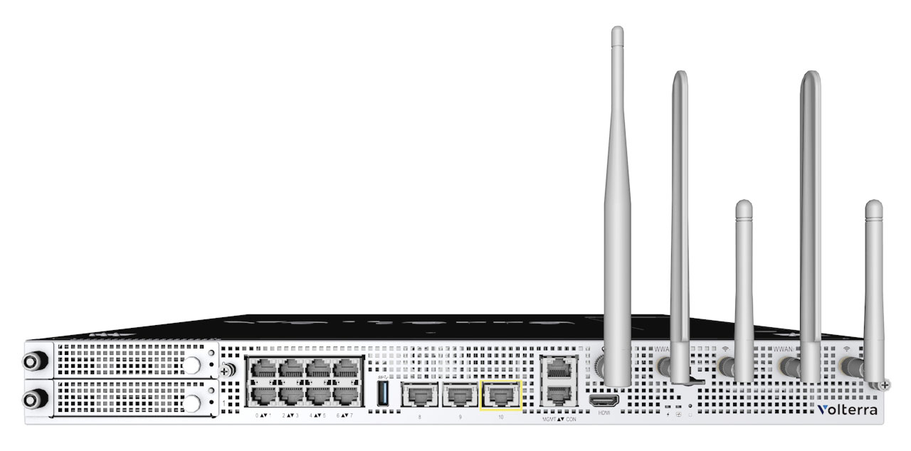
Figure: F5 Volterra Industrial Server 8000
The following video presents an overview for the ISV 8000 series:
Note: See ISV Datasheet for detailed technical specifications.
ISV Variants
ISVs are available in a few configurations:
- With an Nvidia Tesla T4 GPU pre-installed.
- With an Nvidia Quadro P1000 GPU pre-installed.
- Without a GPU installed.
If you choose an ISV without an installed GPU, you can install a GPU later. See GPU installation instructions.
There are also some port indicator differences based on the version of your ISV. Those differences are noted in the Ports section.
Installation
Rack Mount (Sliding Mount)
- Align system brackets to sides of ISV8000 and secure with included screws.
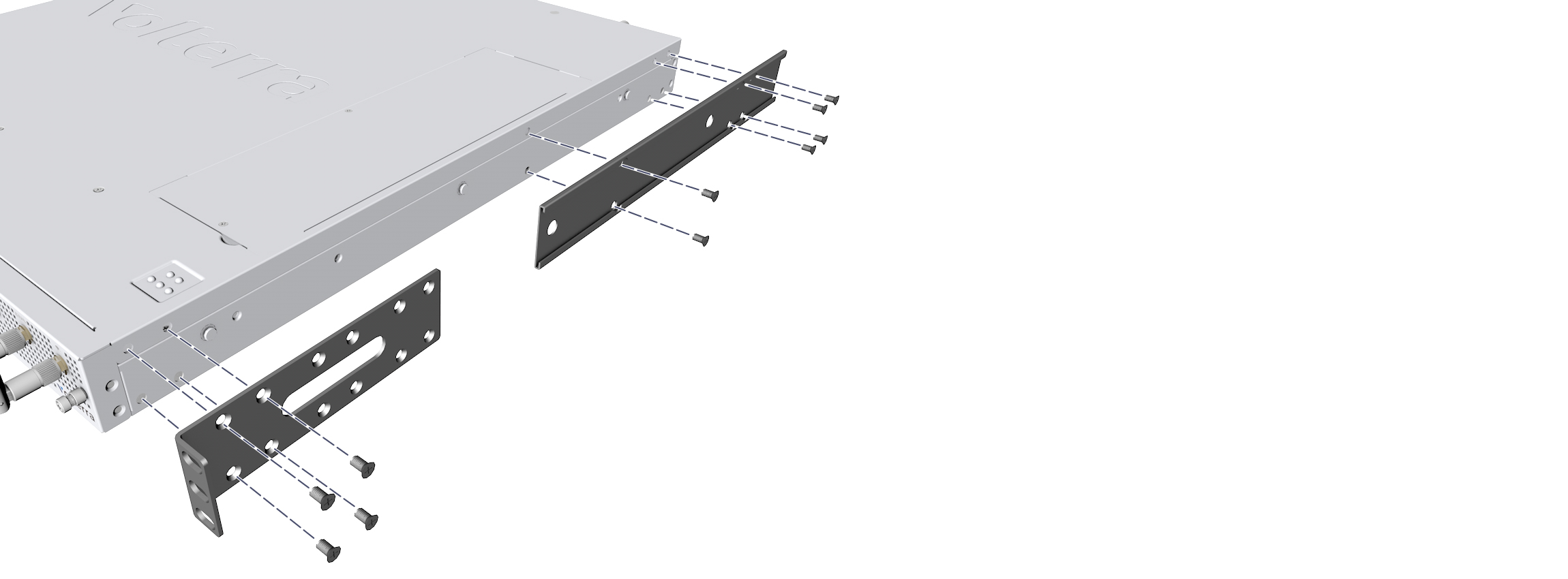
Figure: System Bracket Attachment
- Attach rack bracket to back of rack with included screws.
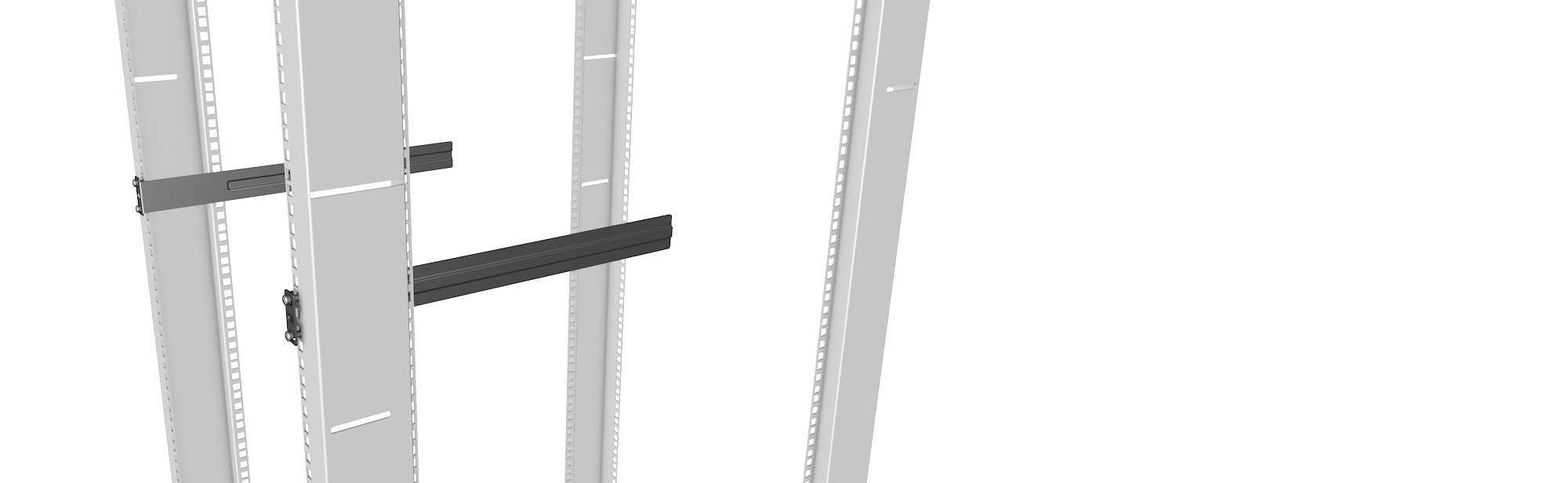
Figure: Rack Bracket Attachment
- Slide the system into rack bracket and secure to front of the rack with included screws
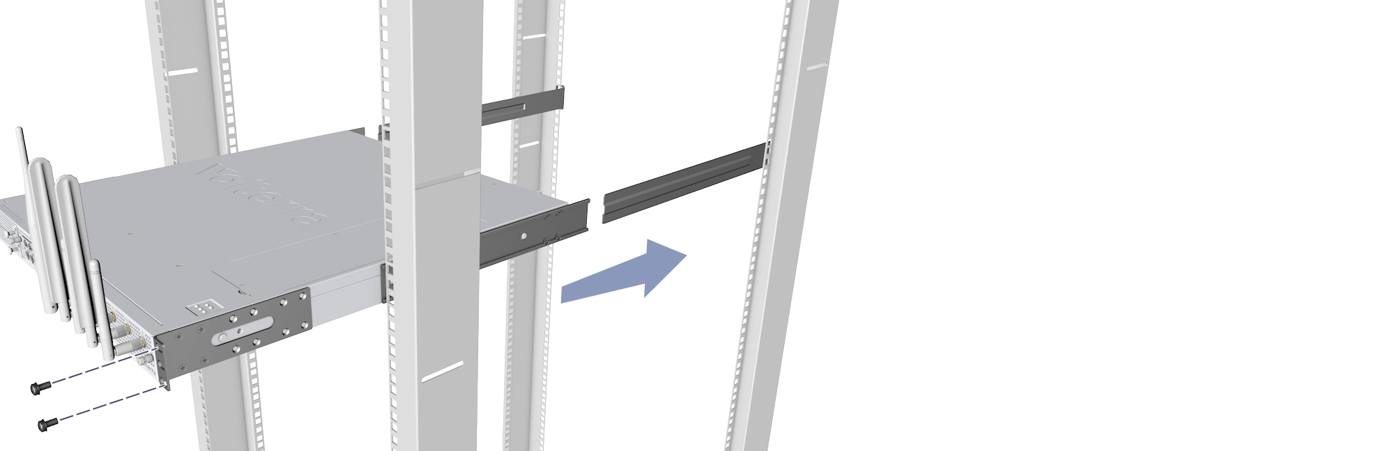
Figure: Sliding ISV Rack Mount
Rack Mount (Fixed Mount)
- Align system brackets to sides of ISV8000 and secure with included screws.
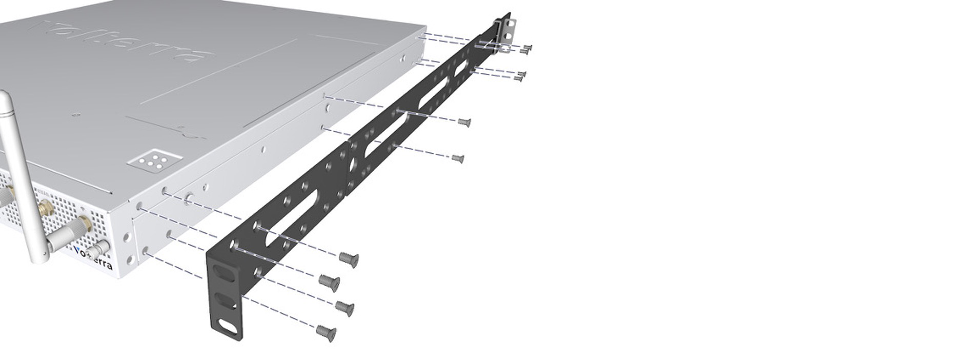
Figure: System Bracket Attachment
- Attach rack bracket to back of rack with included screws.
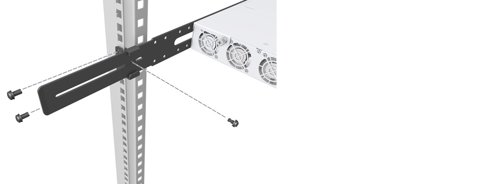
Figure: Rack Bracket Attachment
- Secure system to front and back of the rack with included screws.
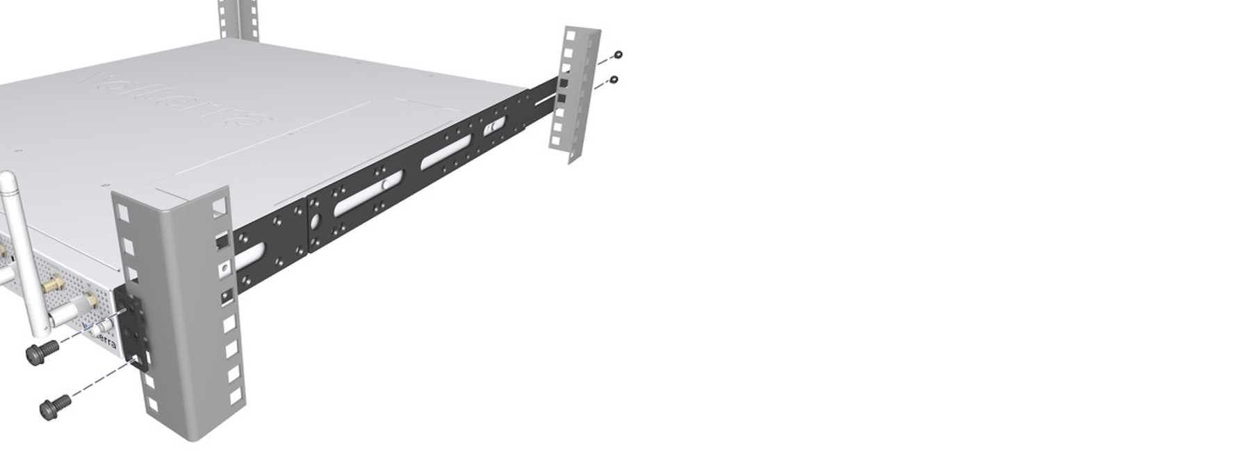
Figure: Fixed ISV Rack Mount
AC Power
- Insert AC power cord as shown in the following image:
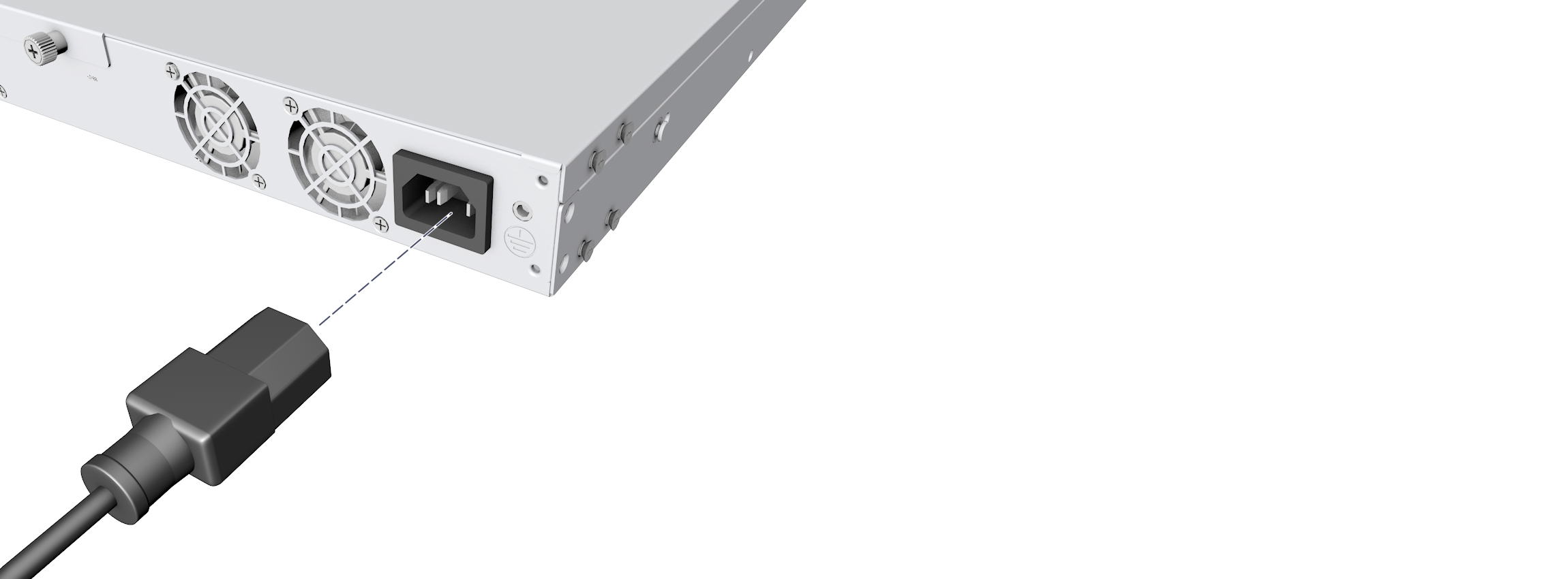
Figure: ISV Power Connection
Antennas
- Install GNSS, LTE & W-Fi antennas as indicated in the following image:
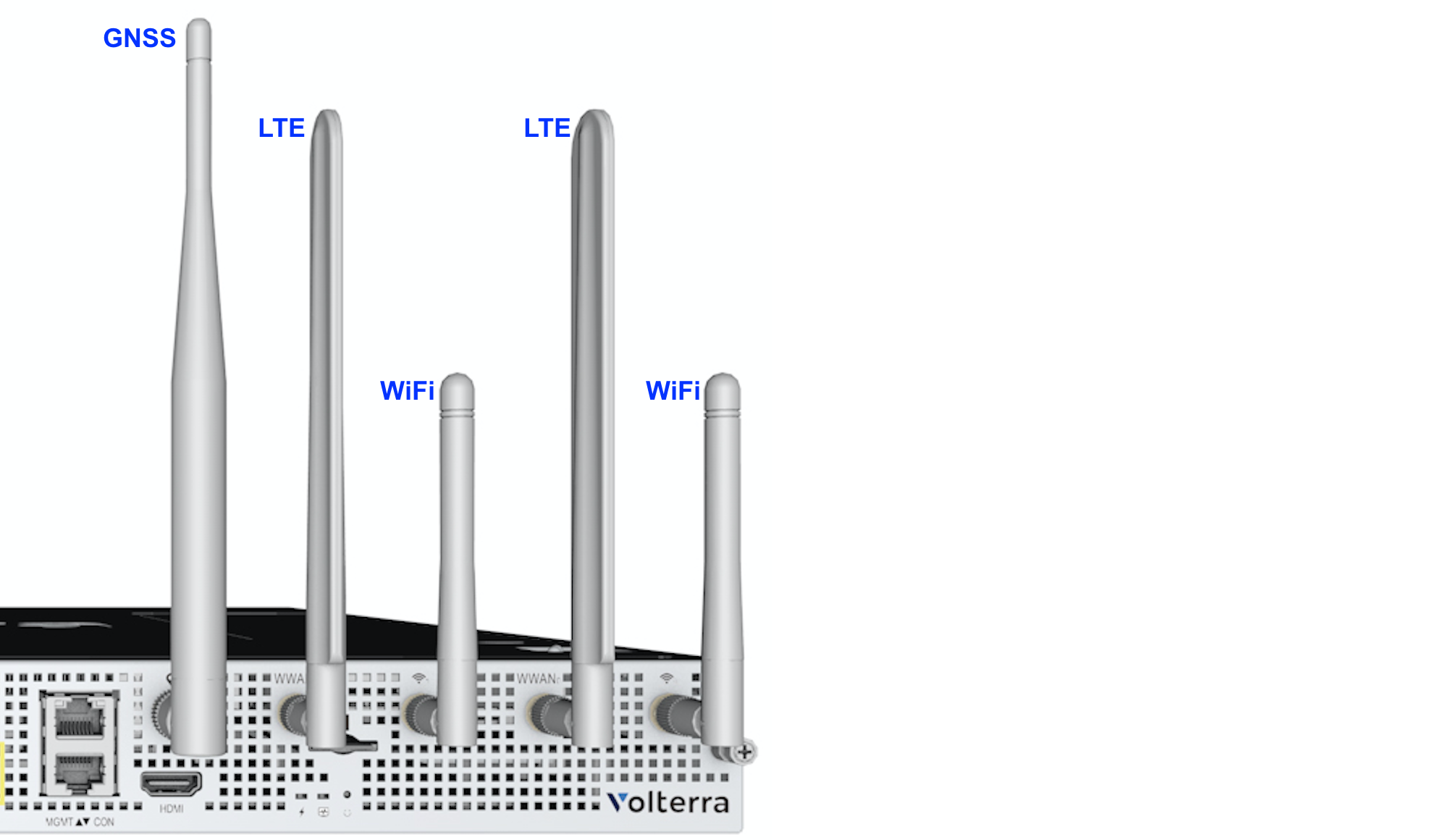
Figure: ISV Antenna Positions
SIM (Optional)
- Insert SIM with the indicated orientation into the slot.
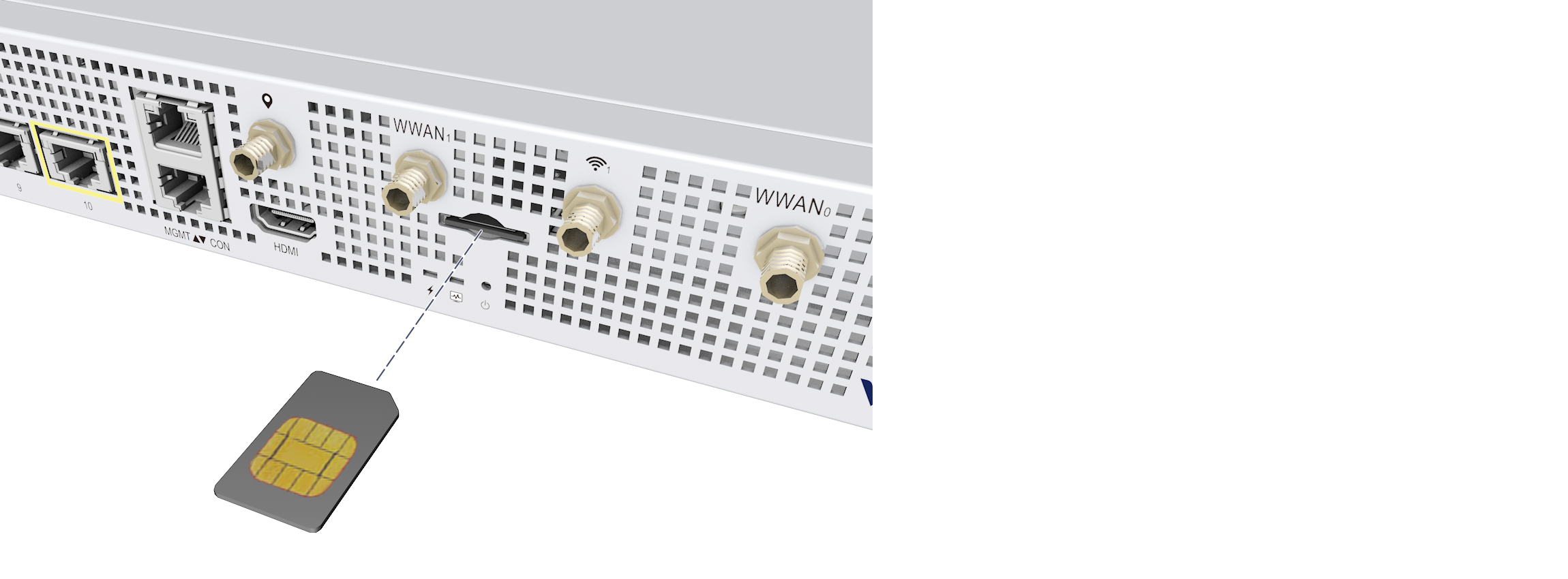
Figure: LTE SIM Slot
GPU (Optional)
- Remove GPU cover by unscrewing the two screws as indicated in the following image:
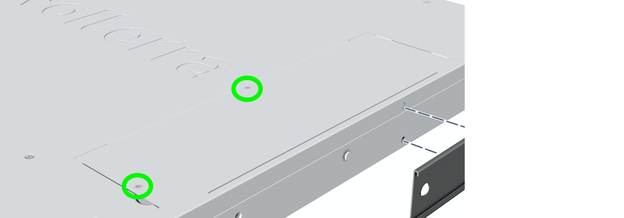
Figure: GPU Cover
- Remove riser assembly from ISV by unscrewing the two screws as indicated in the following image:
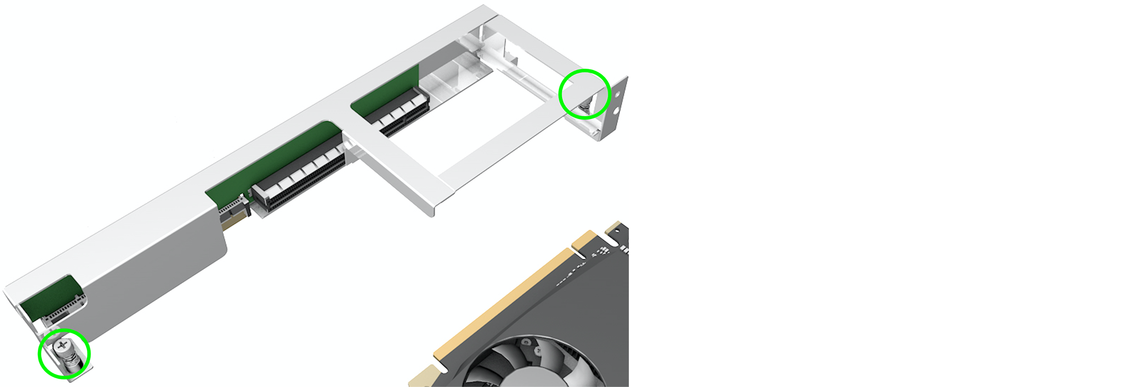
Figure: ISV Riser Assembly
- Insert GPU into riser assembly.
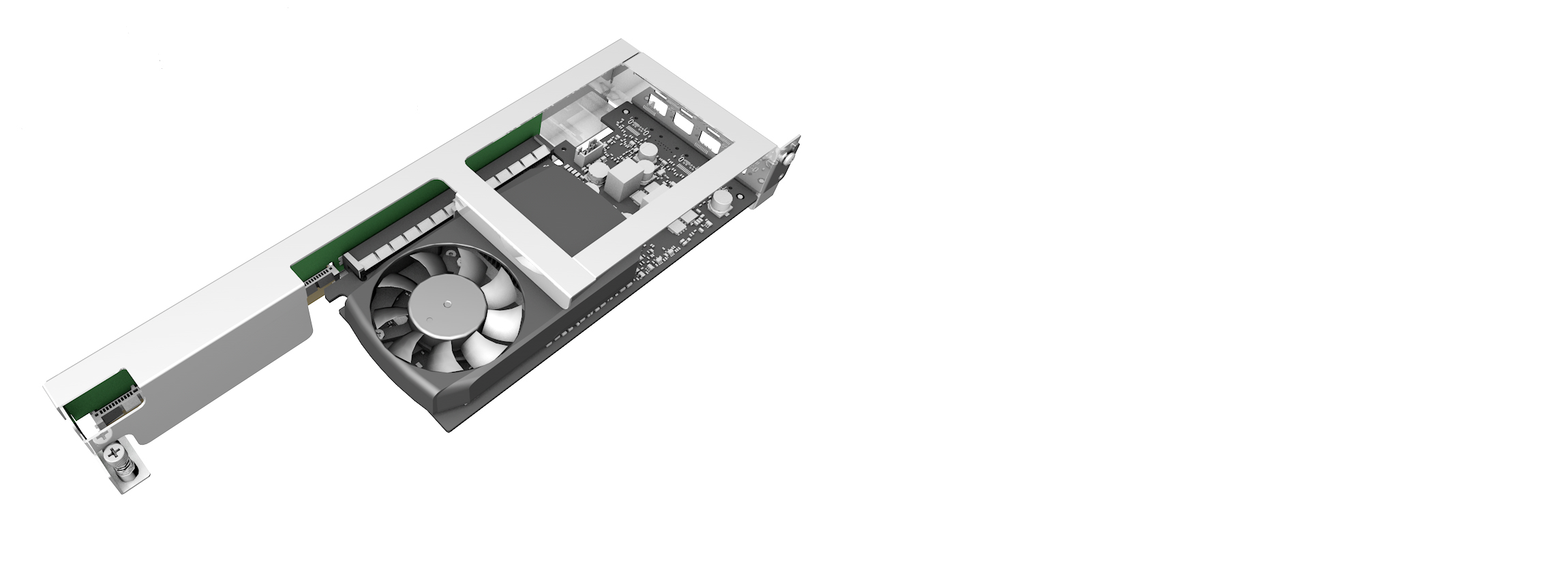
Figure: GPU Insertion into Riser Assembly
- Insert riser assembly with GPU into ISV (secure with the two screws) and reinstall GPU cover (secure with the two screws).
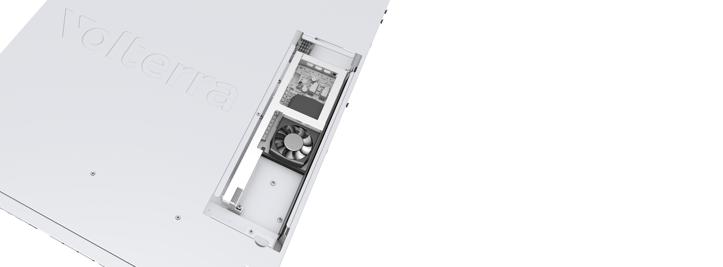
Figure: GPU Insertion to ISV
Air Filter (Optional)
Attach the air filter to the front panel and secure with the two thumb screws.
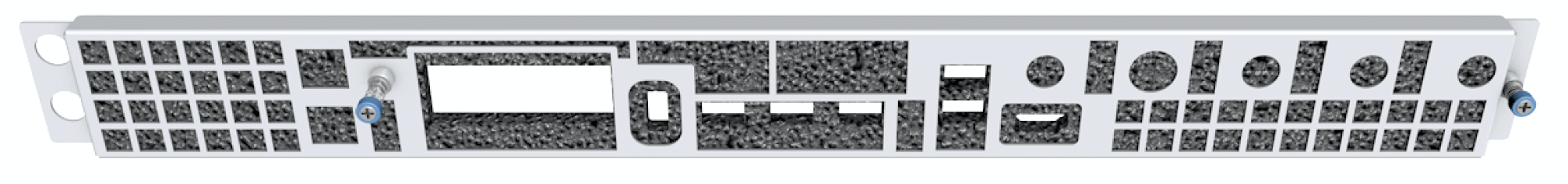
Figure: ISV Air Filter Attachment
Ports
Network Ports
There are eight 1G ports (eth0-eth7). These ports can operate in 10M/100M/1G modes. Each 1G port supports POE (both 802.3af and 802.3at).
Note: the total POE power budget is 126.2W and the guard band is 3W.
There are three 10G ports (eth8-eth10). The 10G ports can only operate in 1G or 10G mode.
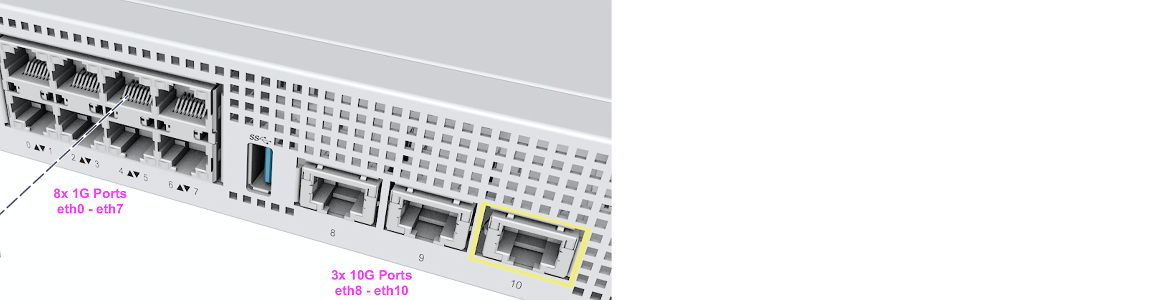
Figure: ISV Port Positions
1G Port LEDs (eth0-eth7)
The LEDs on all eight eth0-eth7 ports exhibit the following behavior:
-
ISVs produced through September 2021:
-
Left LED - indicates port speed:
- LED OFF - indicates the port is in 10/100 mode
- LED ON (solid green) - indicates the port is in 1G mode
-
Right LED - will blink to indicate link/activity
-
-
ISVs produced after September 2021:
-
Left LED - will blink to indicate link/activity
-
Right LED - will indicate port speed via different blink rates:
- 1G - blink at 84msec
- 100M - blink at 170msec
- 10M - blink at 340msec
-
10G Port LEDs (eth8-eth10)
The LEDs on all three 10G ports exhibit the following behavior:
-
For ISVs produced through September 2021:
- Left LED - will be blinking to indicate link/activity
- Right LED - will be ON (solid green) to indicate speed (for either 1G or 10G)
-
For ISVs produced after September 2021:
- Left LED - will be blinking to indicate link/activity
- Right LED - will be solid yellow to indicate 1G speed or solid green to indicate 10G speed
Console/Management/HDMI Port
-
Lower RJ45 is the serial console port which is configured for 115.2K N81. Use RJ45 rollover cable.
-
Upper RJ45 is the ethernet 1G management port
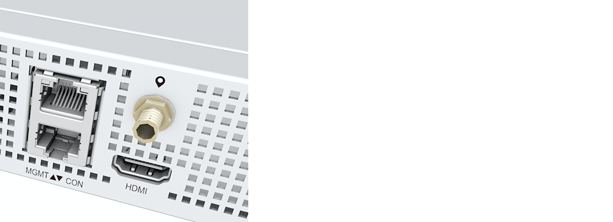
Figure: Console, Management, and HDMI Ports
USB Port
The USB Port supports USB3.0 and USB2.0
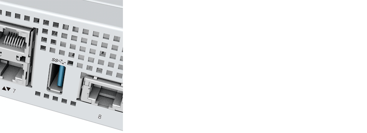
Figure: USB Port
Front Panel Storage
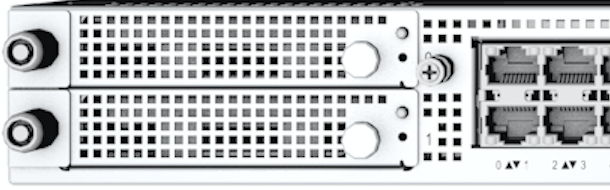
Figure: Storage Slots
There are two 2.5” U.2 slots.
Each slot can support:
- 2.5” HDD SATA
- 2.5” SSD SATA
- 2.5” SSD NVMe
Note: Only HDD/SSD SATA drives are hot swappable.
Installation
- Remove the U.2 tray with the included key.
- Secure drive to tray via four screws as indicated.
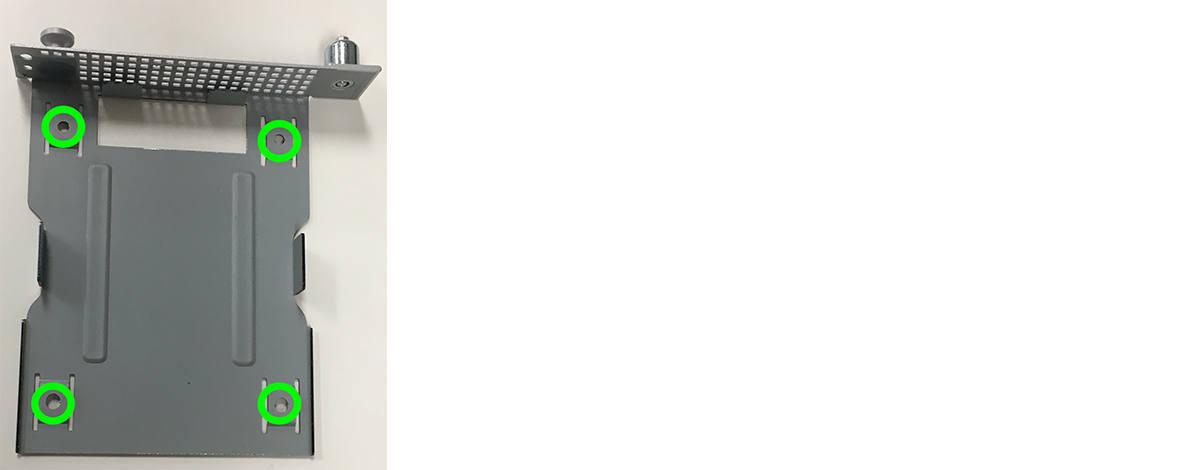
Figure: Storage Installation
System Status
| Display | Image | Description |
|---|---|---|
| Power |  | LED will turn on when the system powers up. |
| System |  | LED is off upon power up and will turn on after BIOS initialization. |
| LEDs Location | 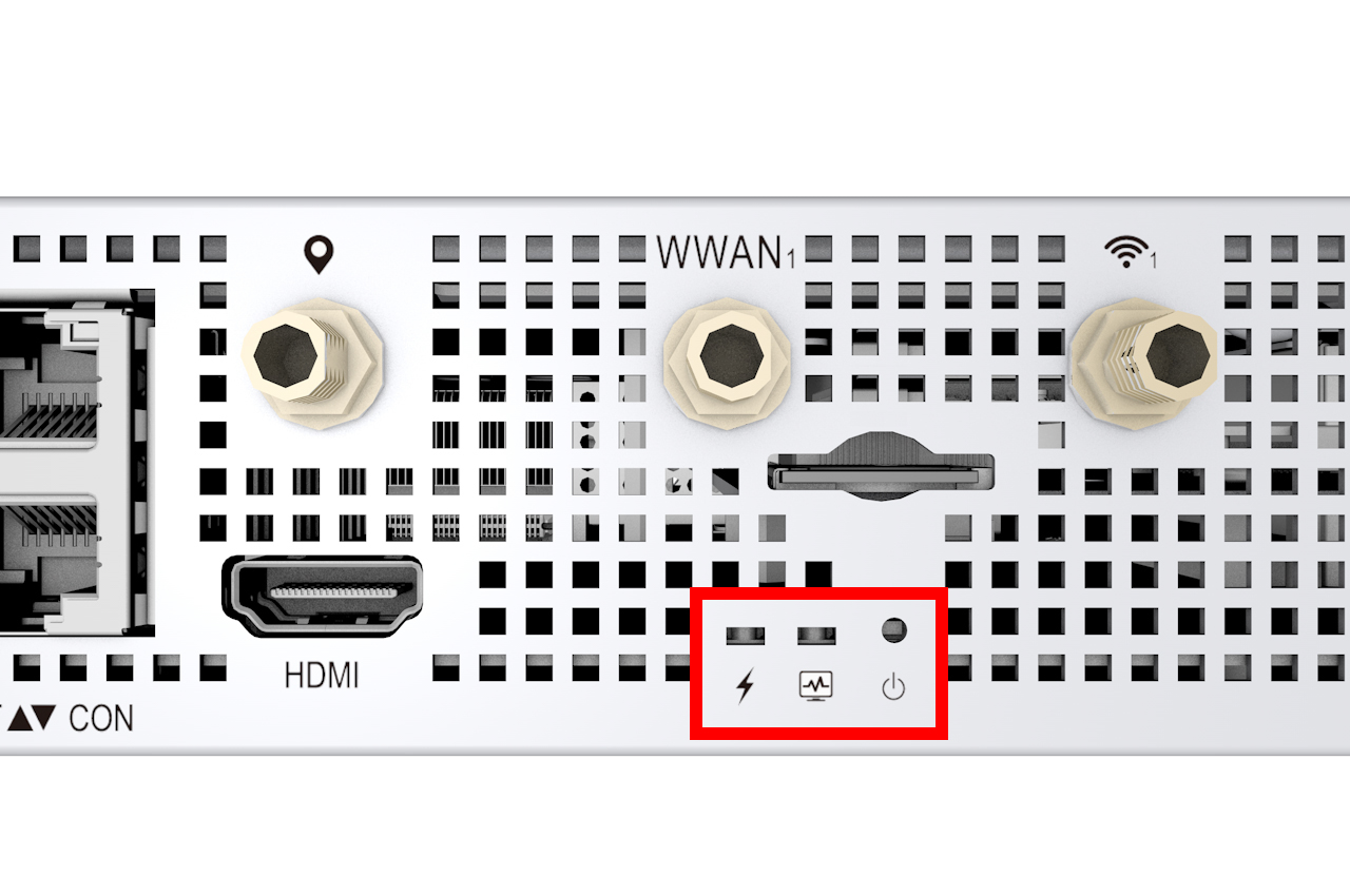 Figure: LED Locations | LED Locations Indicated |
Factory Reset
The factory reset button is next to the system status LEDs on the back panel of the ISV. Pressing this button for at least five seconds will return the ISV to factory settings and restart the device.
To activate the reset function, insert a thin, blunt object (like the end of a paperclip) through the hole above the power icon, ⏻ , and gently push to depress the button inside the hole.
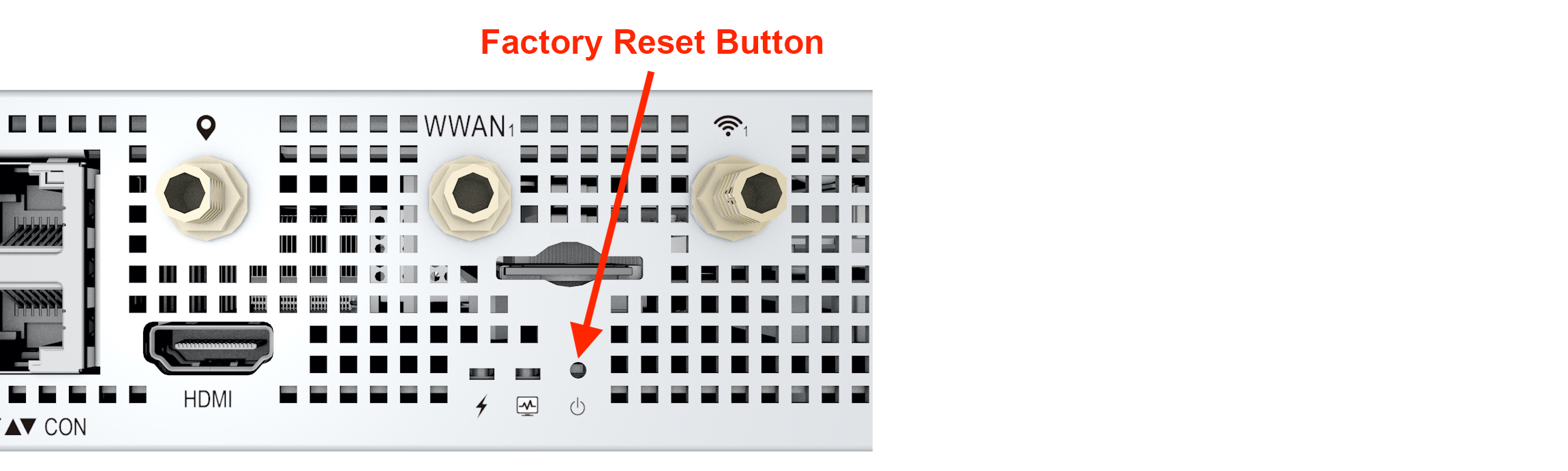
Figure: Hardware Reset Button
Note: The factory reset capability is available on ISV boards with revision
R0Dand above. You can determine the version of the device by (1) usingdmidecodeon the device (look forVersion:in the output) or (2) using the commandsystemctl status vpmf(look forversionorrev).
On this page:
- Objective
- ISV Variants
- Installation
- Rack Mount (Sliding Mount)
- Rack Mount (Fixed Mount)
- AC Power
- Antennas
- SIM (Optional)
- GPU (Optional)
- Air Filter (Optional)
- Ports
- Network Ports
- 1G Port LEDs (eth0-eth7)
- 10G Port LEDs (eth8-eth10)
- Console/Management/HDMI Port
- USB Port
- Front Panel Storage
- Installation
- System Status
- Factory Reset