Industrial Gateway 5000/5500 Series User Manual
Objective
This guide presents detailed information on the F5 Volterra Industrial Gateway (IGW) Series 5000/5500. The information includes instructions on physical installation of the IGW 5000/5500 series devices and details on various operational components such as ports, interfaces, etc.
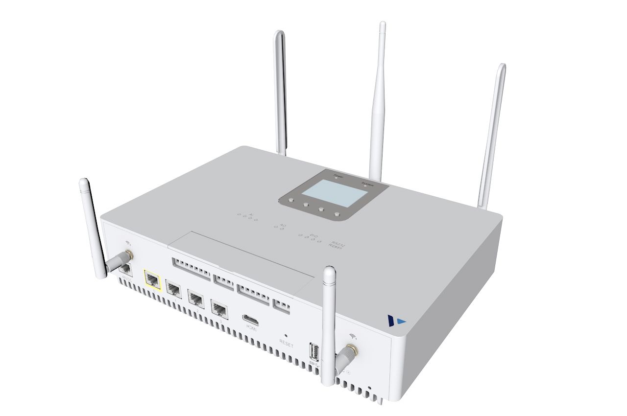
Figure: F5 Volterra Industrial Gateway
The following video presents a brief overview of the F5 Volterra IGW 5000/5500 series:
Note: See IGW Datasheet for detailed technical specifications.
Installation
Mounting
Vertical mounting is supported via DIN or VESA.
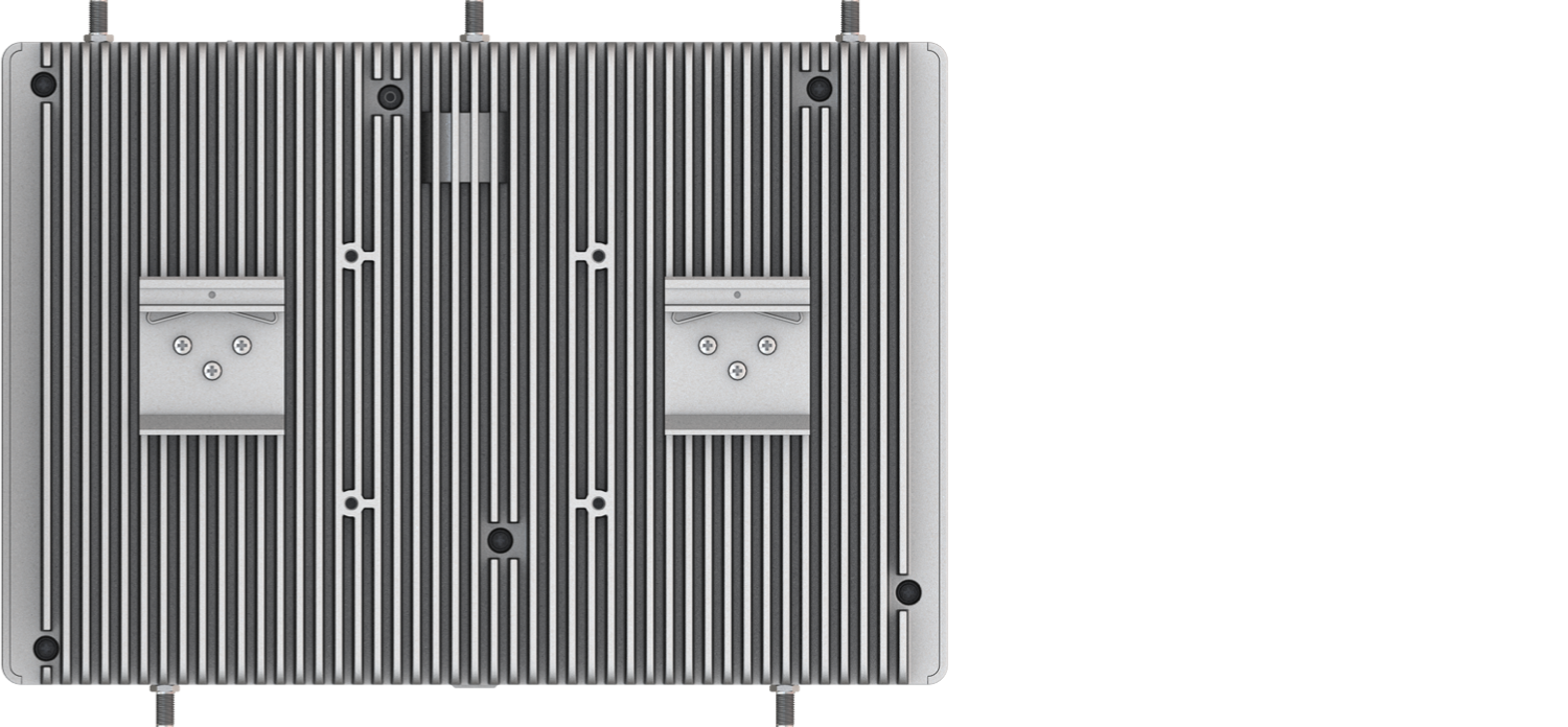
Figure: Mounting Via DIN/VESA
-
For DIN - Attach DIN brackets to the backside of the chassis with the included screws. Hook the chassis onto the DIN rail and snap down.
-
For VESA - the mount system must be able to support VESA 75 and M4*10 screws.
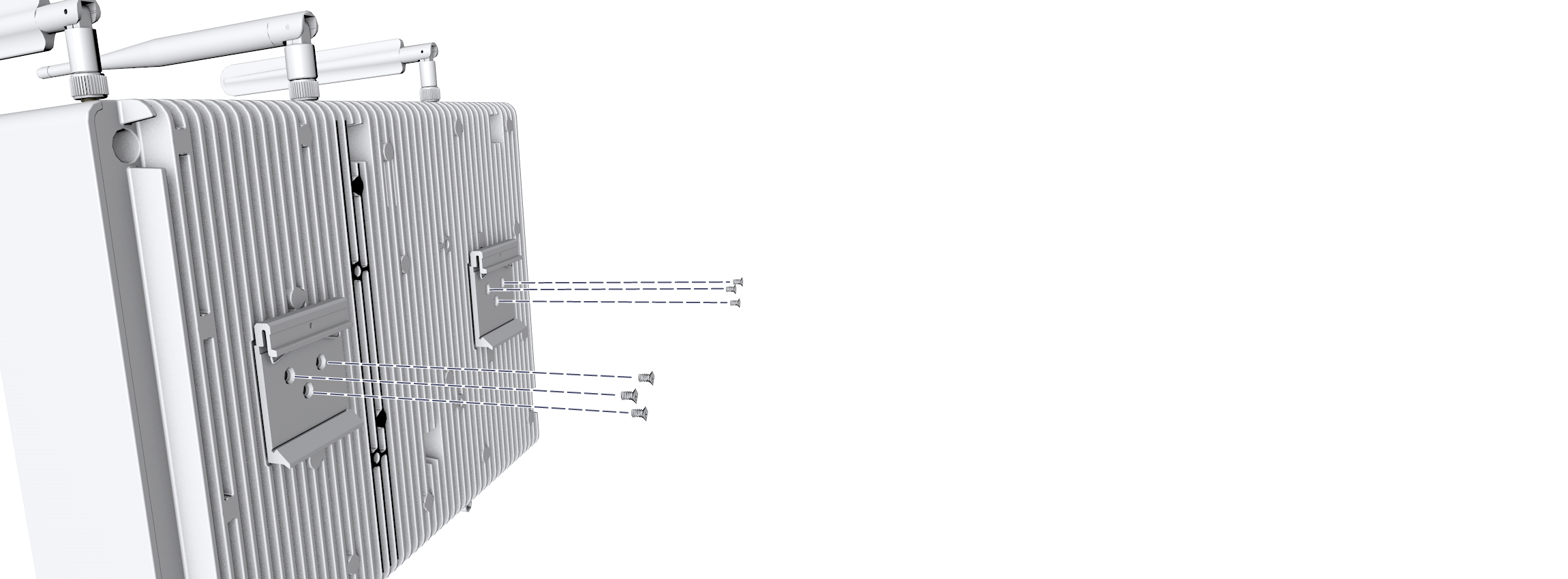
Figure: Attach Brackets with Screws
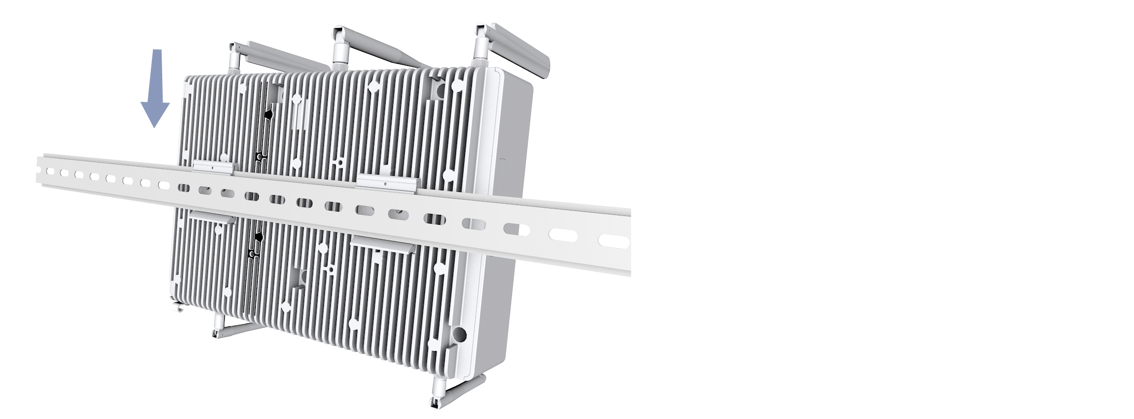
Figure: Mount the System
System Power
Attach system power cable clamp as shown in the following figure. Plug system power cable into the receptacle label 24VDC
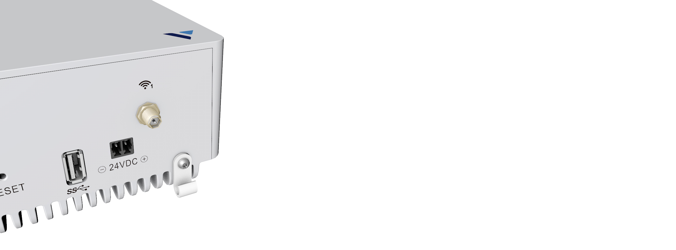
Figure: Power Receptacle
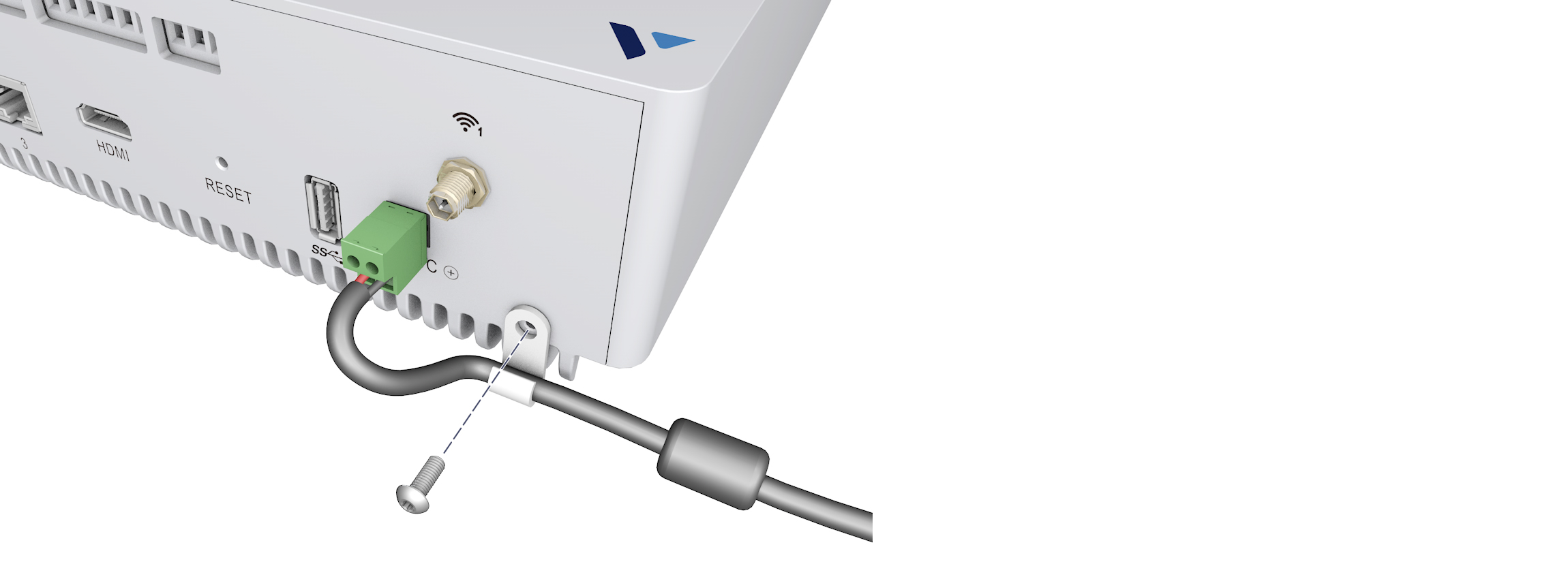
Figure: Power Cable Clamp
POE Power (Optional)
Plug Power Over Ethernet POE PSU cable into RJ45 jack labeled 48VDC
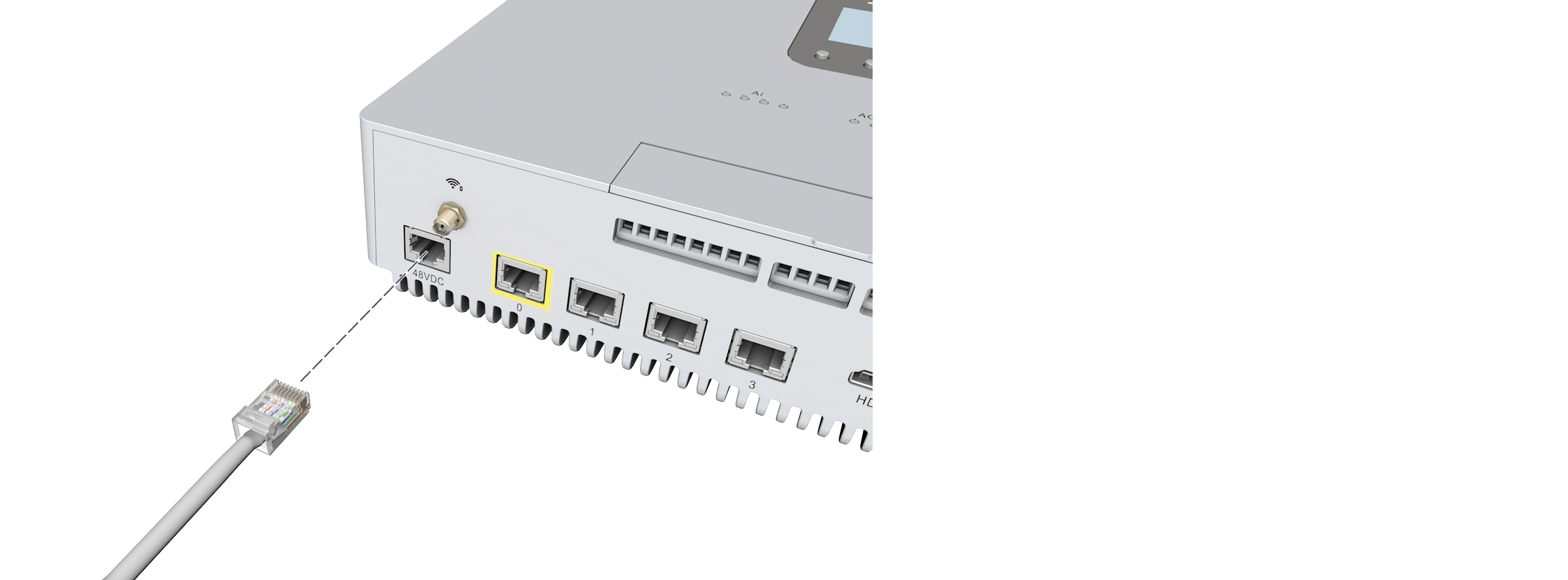
Figure: PoE Jack
Antennas
Install GNSS, LTE & Wi-Fi antennas as indicated in the following figure:
Note: The following image is the Antenna locations on IGW 5500 device. The IGW 5000 device also has antennas on same locations.
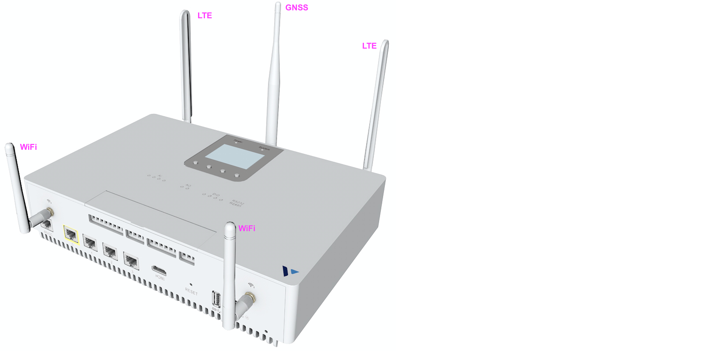
Figure: IGW Antennas
SIM (Optional)
Open cover and insert SIM as indicated in the following figure. After that, close the cover.
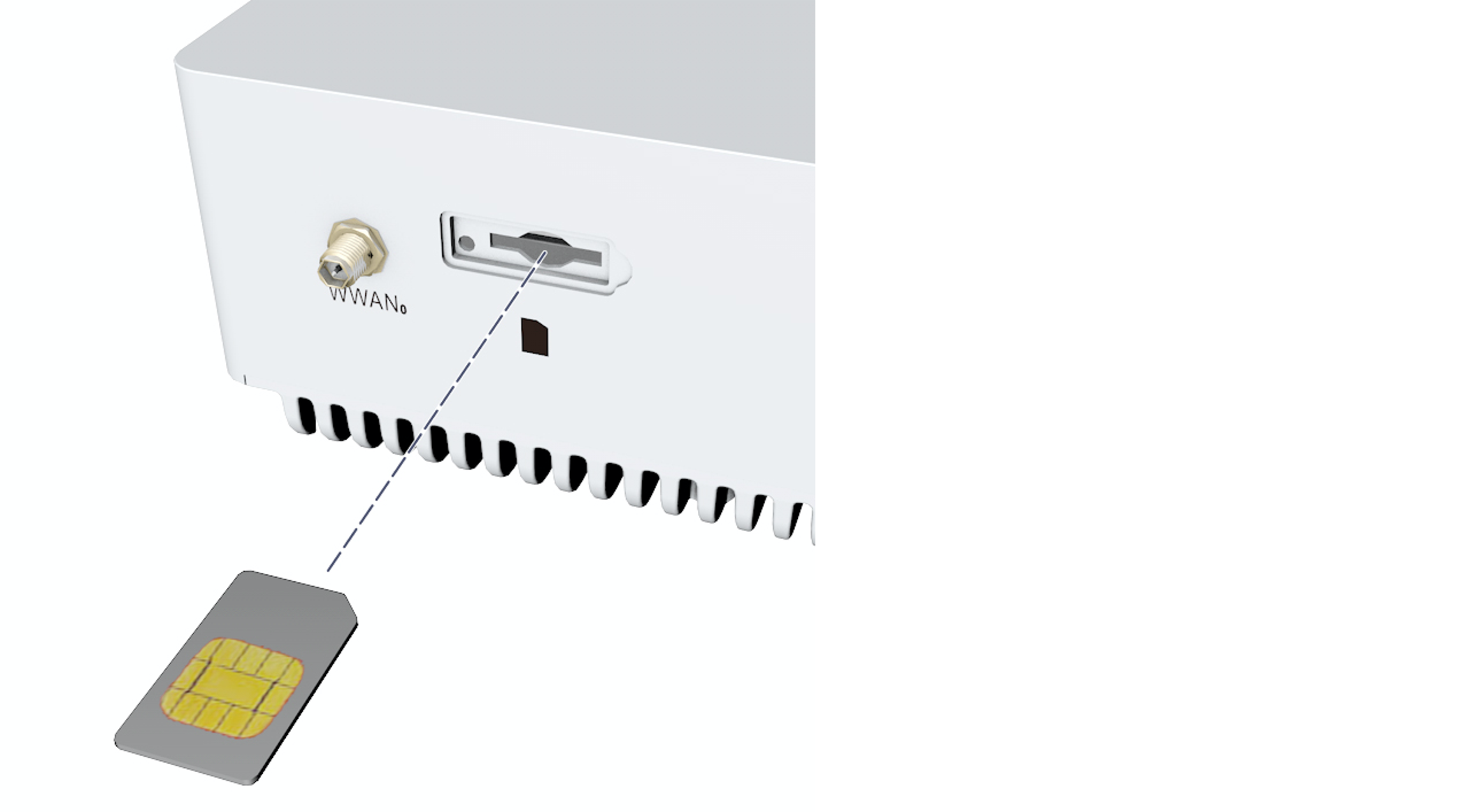
Figure: SIM Cover
Ports
Network Ports
There are four 1G ports (ETH0-ETH3). These ports can operate in 10/100/1G modes. Each 1G port supports POE (both 802.3af and 802.3at).
Note: The POE PSU must be plugged in for POE functionality, and the total POE power budget is 61.6W

Figure: Network Ports
Note: The port ETH0 is the WAN port and indicated with yellow mark surrounding it.
Eth0-3 Port LEDs
The LEDs on all four (Eth0-Eth3) ports exhibit the following behavior:
- Left LED - will blink to indicate Link/activity. The LED color is amber.
- Right LED - will blink to indicate Speed (1 blink for 10M / 2 blinks for 100M / 3 blinks for 1G). The LED color is green.
HDMI / USB Port
The USB Port supports USB3.0 and USB2.0.

Figure: HDMI and USB Ports
System Status
Power and System LEDs
- Power LED will turn on when the system powers up.
- System LED is off upon power up and will turn on after BIOS initialization.
LCD Display and Buttons
- Status Bar - WiFi strength Notifications Bluetooth status
- Notifications
- Status - Site Local Intf: eth0
- Configuration - Reboot and Factory reset
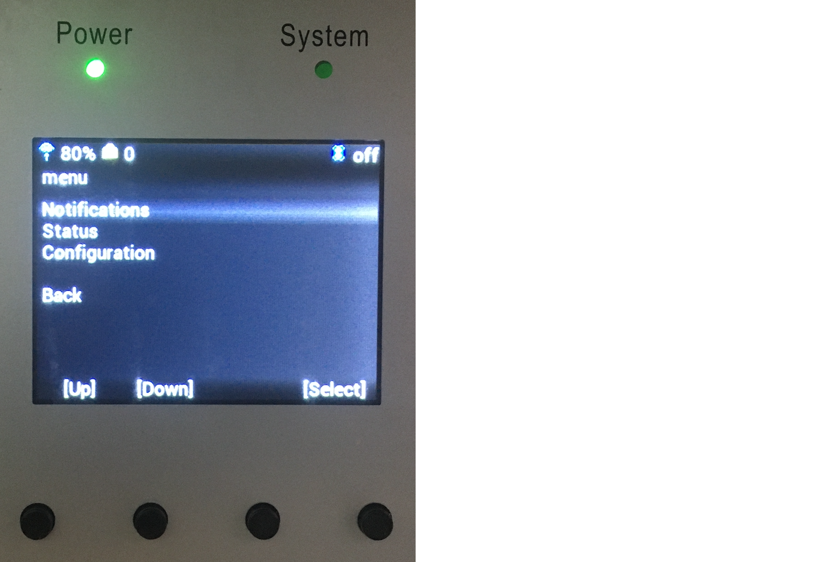
Figure: LCD and System LEDs
Industrial IO LEDs (IGW 5500 Only)
- AI - Analog Input channel active indication
- AO - Analog Output channel active indication
- DIO - Digital IO channel logic state
- RS232/RS485 - Traffic activity indication
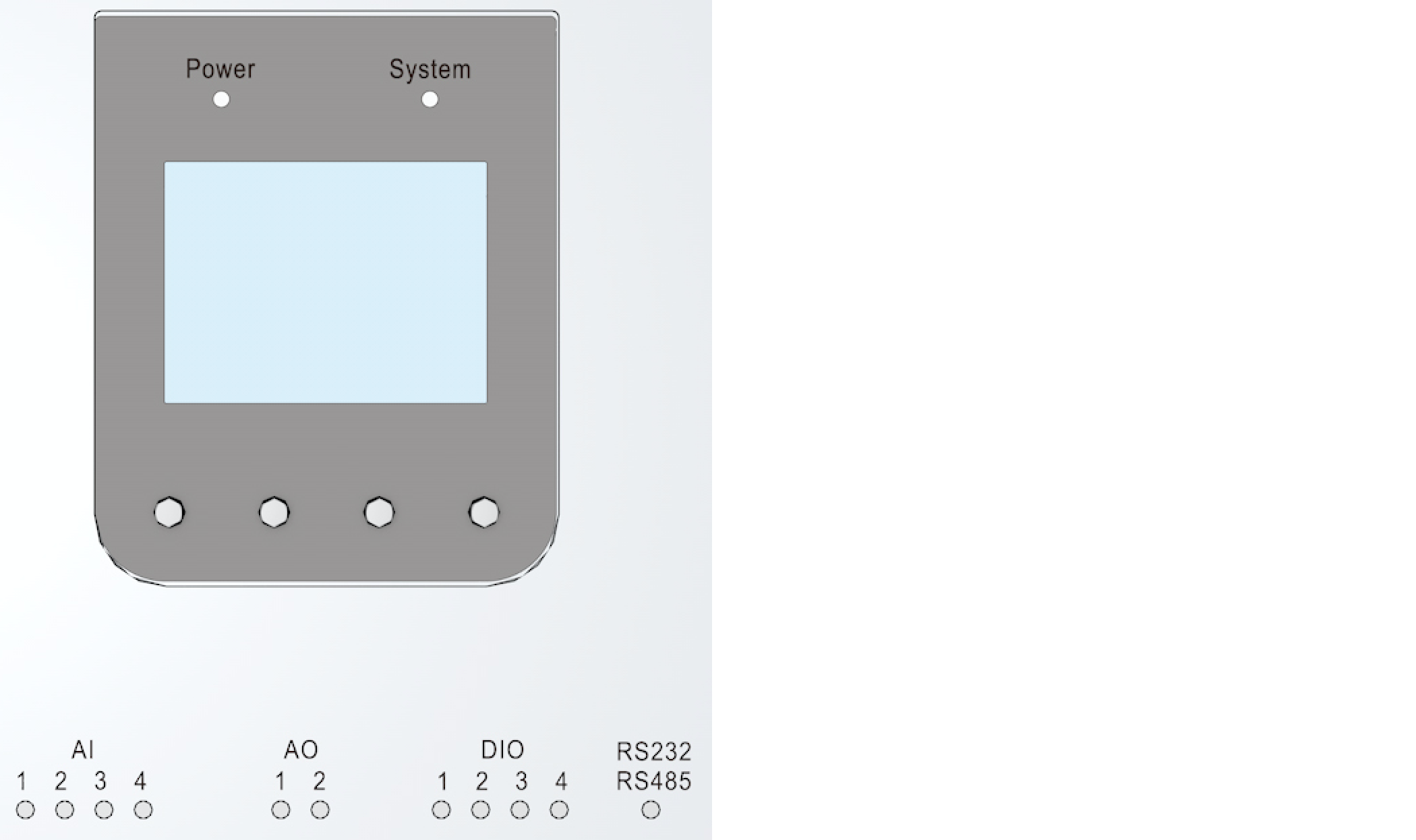
Figure: Industrial IO LEDs
Factory Reset
The front panel contains a RESET button that will return the IGW to factory settings and restart the device.
To activate the reset function, insert a thin, blunt object (like the end of a paperclip) through the hole above the reset label and gently push and hold the button inside the hole for five seconds.
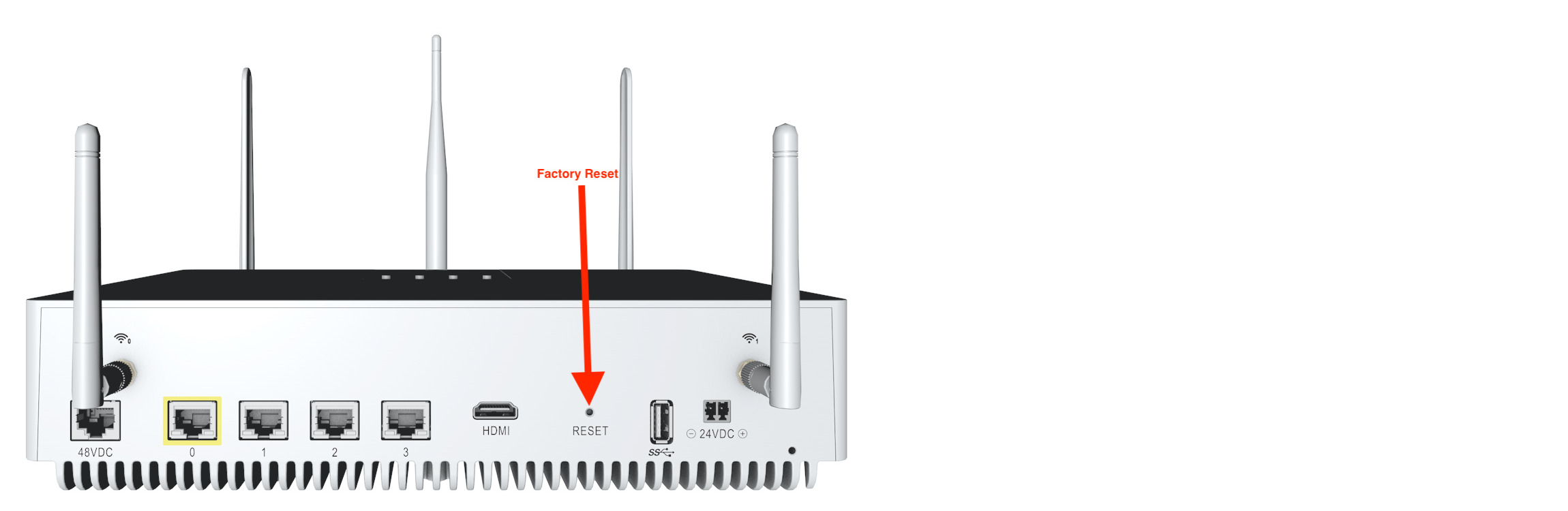
Figure: Hardware Reset Button
Industrial IO (IGW5500 Only)
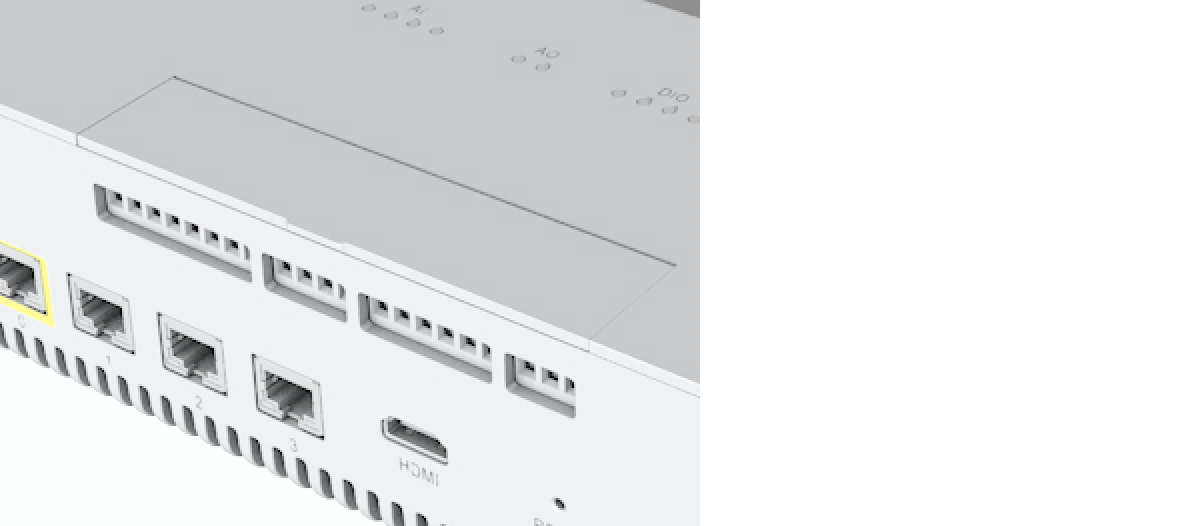
Figure: Industrial IO Indication
IGW 5500 Industrial IO consist of the following:
- AI - Analog Input channels (4)
- AO - Analog Output channels (2)
- DIO - Digital IO channels (4)
- RS232/RS485 port
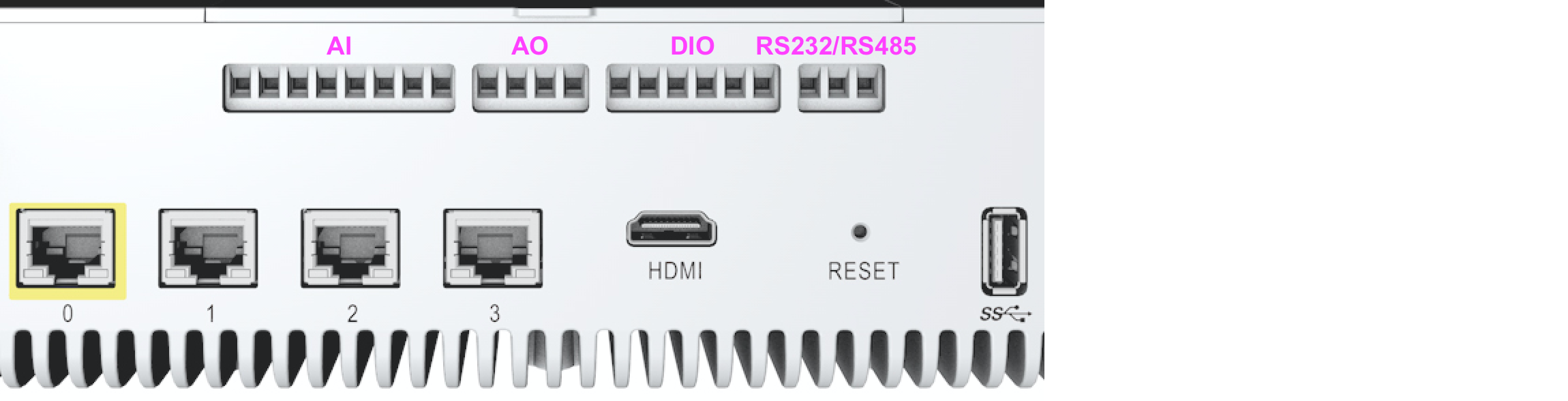
Figure: Industrial IO Channels
Labeling is present on the inside of the door to label each terminal block clamping screw.
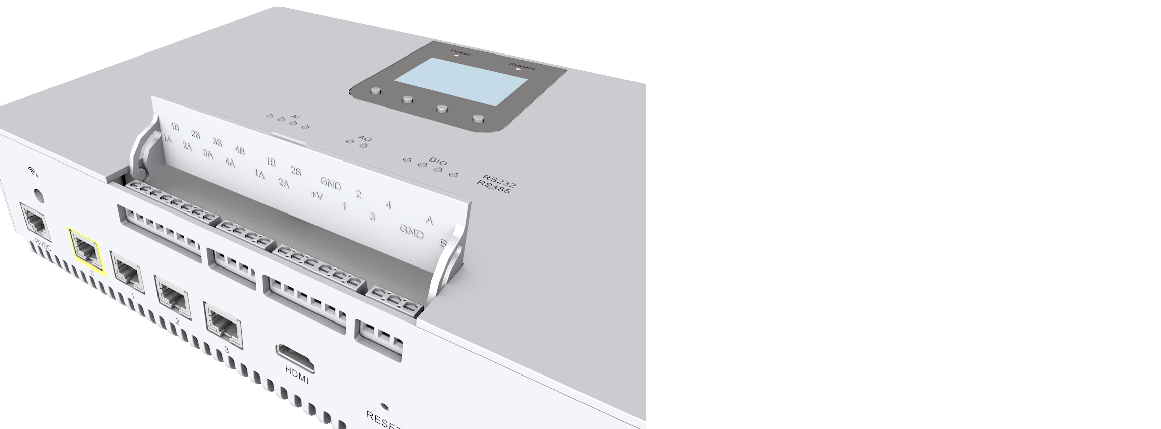
Figure: Labeling on Inside Door
- AI/AO - The
Aside indicates the positive side and theBside indicates the negative side. - DO -
V+is the supply voltage for each DIO channel since each channel has a low side driver(sinking) when configured as an output. - RS232 - The
Aside indicates transmitting and theBside indicates receiving.
The Industrial IO door will cover the terminal block clamping screws. The terminal block clamping screws can be accessed from the front of the chassis when the door is open. The wire entry will be from the bottom of the chassis.
Note: Wires from 12-28AWG are supported.
Industrial IO specification
Analog Input
Sensors: Temperature/Pressure
- Voltage input ranges (with Typical ZIN of 1 MΩ): ±10V / ±5V / ±2.5V / 0 to 10V / 0 to 5V
- Current input ranges (with ZIN of 300 Ω): 0 to 20mA / 4 to 20mA / ±20mA
Analog Output
Sensors: Linear Actuators/Proportional Valves/Servo Drives
- Voltage output ranges: 0 to +5V / 0 to +10V / ±5V / ±10V / 0 to +6V / 0 to +12V / ±6V / ±12V
- Current output ranges : 3.5mA to 23.5mA / 0 to 20mA / 0 to 24mA / ±24mA / 4 mA to 20mA
Digital Input/Output
Sensors: Proximity(DI)/Servo Motor(DO)/Stepper Motor(DO)
- Each channel can be configured for input or output independently
- IEC 61131-2 Type 1-3 is supported (DI)
- Max counting frequency 100Khz (DI)
- Max PTO frequency 100Khz (DO)
RS232/RS485
Sensors: HMI/VFD/Modem
- Port configurable for RS232 or RS485
- RS485: Up to 10 Mbps, 2-wire, half-duplex
- RS232: Up to 1 Mbps, 2-wire, full-duplex
Note: The data rate highly depends on the cable length. The rule of thumb to be followed is
X bit/sec * Y meter <= 100M.