Create Baremetal Site
Objective
This document provides instructions on how to create an F5® Distributed Cloud Services single-node or multi-node Customer Edge (CE) Site on custom hardware, with a software image file.
Prerequisites
- A Distributed Cloud Services Account. If you do not have an account, see Getting Started with Console.
- A Distributed Cloud Services node software image file. To download the software image file, see Images.
- Resources required per node:
- Minimum 8 vCPUs and 32 GB RAM.
- 80 GB is the minimum amount required for storage. However, to deploy an F5 Distributed Cloud App Stack Site, F5 recommends 100 GB for storage.
Note: For a full listing of the resources required, see the Customer Edge Site Sizing Reference guide. All the nodes in a given CE Site should have the same resources regarding the compute, memory, and disk storage. When deploying in cloud environments, these nodes should use the same instance flavor.
-
Allow traffic from and to the Distributed Cloud public IP addresses to your network and allowlist related domain names. See F5 Customer Edge IP Address and Domain Reference for Firewall or Proxy Settings guide for the list of IP addresses and domain names.
-
Internet Control Message Protocol (ICMP) needs to be opened between the CE nodes on the Site Local Outside (SLO) interfaces. This is needed to ensure intra-cluster communication checks.
Important: After you deploy the CE Site, the IP address for the SLO interface cannot be changed. Also, the MAC address cannot be changed.
By proceeding with the installation, download and/or access and use, as applicable, of the Distributed Cloud Services software, and/or Distributed Cloud Services platform, you acknowledge that you have read, understand, and agree to be bound by this agreement.
Restrictions
The USB allowlist is enabled by default. If you change a USB device, such as a keyboard after registration, the device no longer functions.
Minimum Hardware Requirements
The Distributed Cloud Services Node software is designed to work on most commodity hardware.
Use the following minimum requirements to help you choose your commodity hardware for Distributed Cloud Services Node deployments:
| Memory | Networking | USB | HDMI | Disk Space |
|---|---|---|---|---|
| Minimum: 14 GB | Minimum: 1x 1000 Mb/s (Intel-based) | Minimum: 1 USB 2.0/3.0 for Imaging the host | Minimum: 1 HDMI for imaging the system. Only required if the hardware provided is not Distributed Cloud Services packaged. | Minimum: 80 GB |
| Recommended: 16 GB | Distributed Cloud Services provides multiple network interface controller (NIC) support. You can use multiple NICs for a CE Site. | Varies with peripheral connections (camera, and more) | Recommended: 128 GB |
As you plan for your hardware setup, consider the following information:
- Current architecture supported is x86. Arm is currently on the roadmap.
- Memory, storage, and CPU requirements vary based on application usage on the system/host.
- Data Plane Development Kit (DPDK) support is a mandatory requirement. Refer to Intel DPDK for more information.
- USB requirements for the host vary on the number of peripheral device connections.
Supported Hardware
-
All the hardware listed below has been tested and supported by Distributed Cloud Services. Known caveats are listed in the respective sections.
-
Distributed Cloud Services nodes can only be deployed on hardware with Intel-based Ethernet cards with DPDK support. See Intel DPDK.
-
Refer to product-specific data sheets for more information.
-
Using the minimum hardware requirements listed above, you can attempt to install a Distributed Cloud Services Node, but official support is limited.
Note: The Distributed Cloud Services Node software is certified to run on the hardware specified in the following sections. If you want to certify Distributed Cloud Services Node software for your specific hardware setup, email sales@cloud.f5.com.
Edge Hardware
| Vendor | Model | Processor | Memory | Networking | Storage | USB | HDMI | Graphics | Input Voltage |
|---|---|---|---|---|---|---|---|---|---|
| Intel | NUC7i7DNKE | 1.9 GHz Intel Core i7-8650U quad-core processor | 32 GB DDR4 SO-DIMM RAM 2400 MHz | 1x Intel 10/100/1000 Gigabit Ethernet | 1 TB SSD SATA III | 4x USB 3.0 | 2x HDMI 2.0 | Dual HDMI 2.0a, 4-lane eDP 1.4 | 12-24 VDC |
| Intel | NUC8i3BEH | Intel® Core™ i3-8109U Processor (4M Cache, up to 3.60 GHz) | 32 GB DDR4-2400 1.2V SO-DIMM | 1x Intel 10/100/1000 Gigabit Ethernet | 1 TB M.2 SSD SATA | 5x USB 3.1 Gen 2 3x USB 2.0 | 1x HDMI 2.0a | Intel Iris™ Plus Graphics 655 or Intel UHD Graphics 620 | 12-19 VDC |
| Fitlet2 | E3950 | Intel Atom™ Processor x7 Series E3950 1.6GHz to 2GHz | 1x SO-DIMM 204-pin DDR3L Non-ECC DDR3L-1866 (1.35V) Up to 16 GB | 2x GbE LAN ports (RJ-45), LAN1: Intel I211 GbE controller, LAN2: Intel I211 GbE controller | 1x M.2 M-Key 2242/2260* on board *M.2 2280 optional on some facet cards | 2x USB 3.0 and 2x USB 2.0 | HDMI 1.4 3840x2160 @30Hz | Intel® HD Graphics 505 Dual display mode supported | Unregulated 7 – 20 VDC* input |
Note: Fitlet2 interface naming is reversed. Eth2 = eth0 (WAN/Site Local Interface) and Eth1 = (LAN/Site Local Inside Interface).
Server Hardware
| Vendor | Model | Processor | Memory | Networking | Storage | USB | RAID | HDD | Input Voltage |
|---|---|---|---|---|---|---|---|---|---|
| Kingstar | SYS-1029U-TN10RT | Intel Xeon | DDR4-2666 32 GB x 12 (384 GB+) | Intel XXV710 (10/25G) | SSD NVMe (1 TB, 4 TB) | ||||
| Dell | PowerEdge R640 | Intel Xeon Gold 6230N (20 Core/2.3 GHZ/27.5 MB Cache/HT) x2 | 384 GB:32 GB*12 - DIMM | Intel X710 10G SFP + x2 Port + Intel i350 1G Base-T x2 Port Add-on: Intel X710 10G SFP+x2 Port PCIe NIC x1 or Intel XL710 40G QSFP+ x2 Port PCIe NIC x2 | 960 GB (mixed use SDD/Dell AG Drive) x3 (6 GBPS SATA/2.5inch/HotPlug) | 2 x USB 3.0 | PERC H740P SAS RAID controller | 960 GB (mixed use SSD/Dell AG Drive) x3 (6 Gbps SATA/2.5inch/HotPlug) | 1100W 48 VDC |
| Dell | PowerEdge R650xs | Intel Xeon Gold 6336Y (24 Core/2.4 GHz/36 MB Cache/HT) | 384 GB(12 x 32GB DDR4 RDIMM,3200 MT/s, Dual Rank) | Intel E810-XXV Quad Port 10/25 GbE SFP28 OCP NIC 3.0 | 960 GB SSD SATA Read Intensive 6 Gbps 512 2.5 inches Hot-Plug AG Drive, 1 DWPD x3 | 1 x iDRAC Direct (Micro-AB USB) 2 x USB 2.0 1 x USB 3.0 | PERC H755 SAS | 960 GB SSD SATA Read Intensive 6 Gbps 512 2.5 inches Hot-Plug AG Drive, 1 DWPD x3 | 800W, 100-240 VAC/240 VDC |
| Dell | PowerEdge R660 | Intel Xeon Silver 4416+(20 Core/2.0 GHz/37.5 MB Cache/HT) | 768 GB(12 x 64 GB DDR5 RDIMM,4800 MT/s, Dual Rank) | Intel X710-T4L Quad Port 10 GbE BASE-T, OCP NIC 3.0; Intel X710-T2L Dual Port 10GbE BASE-T Adaptor, Low Profile PCIe | 960 GB SSD SATA Read Intensive 6 Gbps 512 2.5 inches Hot-Plug AG Drive, 1 DWPD x4 | 1 x iDRAC Direct (Micro-AB USB) 2 x USB 2.0 1 x USB 3.0 | PERC H965i, PERC H755, PERC H755N, PERC H355, HBA355i, PERC H965e | 960 GB SSD SATA Read Intensive 6 Gbps 512 2.5 inches Hot-Plug AG Drive, 1 DWPD x4 | 1100W |
| HP | ProLiant DL360 Gen10 8SFF NC | Intel Xeon Gold 6222V (20 Core, 1.8 GHZ, 27.5 MB Cache) x 2 | 32 GB x 12 (384 GB) DIMM | 2x HPE Ethernet 10/25 Gb 2-port SFP28 interfaces (Mellanox MCX4121A ConnectX-4 Lx), 1x HP Ethernet 1 Gb 4-port 366T Adapter (Intel) | 2 x USB 3.0 | PERC H740P SAS RAID controller | 800W |
Create CE Site
Before you deploy a single-node or multi-node Site on baremetal, you must create a Site object in the F5 Distributed Cloud Console. For information, see one of the following documents:
-
To create a Secure Mesh Customer Edge, see Create Secure Mesh Site.
-
To create an App Stack Customer Edge, see Create App Stack Site.
Prepare Bootable USB
To create a bootable USB drive, you must flash the Distributed Cloud Services CE ISO image onto a USB drive. Depending on your operating system, you can use software, such as Etcher, to quickly flash the USB drive with the ISO image.
Step 1: Download Etcher software based on your operating system.
-
Navigate to Etcher to download the installer file.
-
Follow the instructions to install Etcher.
Note: If you are running macOS X Catalina, you must download the latest version of Etcher. If you do not download the latest version and attempt to flash an ISO image, the following terminal message appears:
“balenaEtcher” can’t be opened because Apple cannot check it for malicious softwareStep 2: Download the Distributed Cloud Services Node ISO image file.
To download the file, go to Certified Hardware and KVM Images. The certified Distributed Cloud Services node image software (.iso/.img) is packaged with all the required components to provision Distributed Cloud Services-based components.
For more information about choosing an appropriate image for your certified hardware, see How to choose an image for your site deployment?.
Step 3: Flash the USB drive.
-
Insert a USB into your computer.
-
Open Etcher.
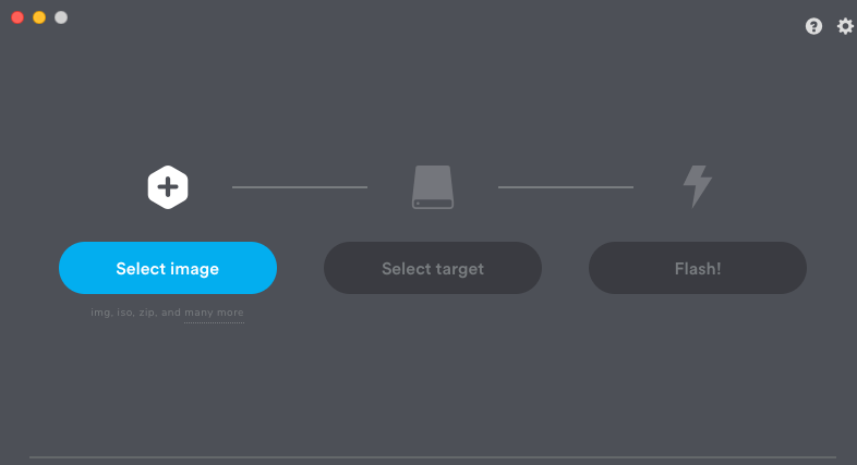
Figure: Etcher
- Follow the instructions to begin the flash process.
Important: You can also use utilities, such as VirtualCD with iDRAC, iLO, and more to boot the Distributed Cloud ISO. For instructions, see the documentation for the utility you want to use.
Configure the BIOS
Prior to installing the Distributed Cloud Services Node software, you must configure your system’s BIOS menu. The BIOS provides the basic functions needed to boot your system and enables you to access specific hardware components.
Step 1: Invoke the BIOS menu.
To enter the BIOS menu, press a key or key combination (Delete or F2) immediately after turning on your computer.
Note: The key combination differs from manufacturer to manufacturer. Typically, the start screen on the computer displays a message that states which key to press to enter the BIOS menu.
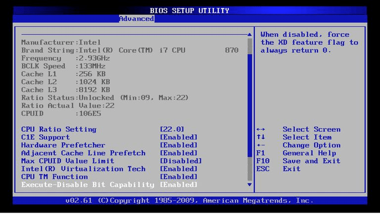
Figure: BIOS Menu
Step 2: Select boot device.
In the BIOS setup menu, you can select which devices will check in which sequence for a bootable operating system in the Boot tab.
Note: The possible choices usually include the internal hard disks, the CD/DVD-ROM drive and mass storage devices, such as USB sticks or external hard disks. The installation media in most of the scenarios is a flashed USB drive with the Distributed Cloud Services Node image.
- Select the USB drive to boot first from the boot menu options.
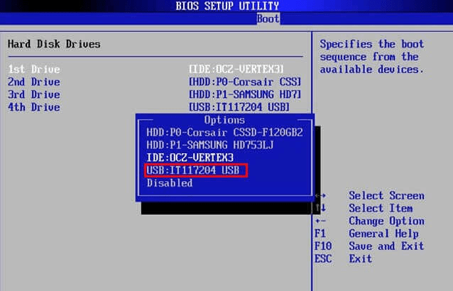
Figure: Selection of Primary Boot Device
Most BIOS versions allow you to call up a boot menu on system startup in which you select from which device the computer starts for the current session. If this option is available, the BIOS usually displays a short message like “press F12 for boot menu” on system startup. The actual key used to select this menu varies from system to system. Commonly used keys are F12, F11, or F8. Choosing a device from this menu does not change the default boot order of the BIOS. In other words, you can start once from a USB drive while having configured the internal hard disk as the primary boot device.
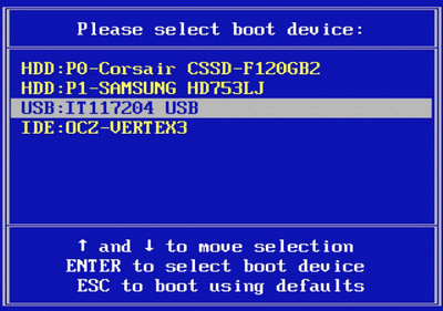
Figure: Selection of Boot Device During System Start
Step 3: Check and fix potential issues.
If you have no PS/2-style keyboard, but only a USB model, you might need to enable legacy keyboard emulation in your BIOS menu to use your keyboard in the bootloader menu. Modern systems do not have this issue.
If your keyboard does not work in the bootloader menu, consult your system manual and look in the BIOS for “Legacy keyboard emulation” or “USB keyboard support” options.
Install the Node OS Software
After the boot order is configured to USB, a prompt loads with information to install the Distributed Cloud Services node OS.
- Use the keyboard arrows to select
Test this media 9 install RHEL 9. This is the recommended option.
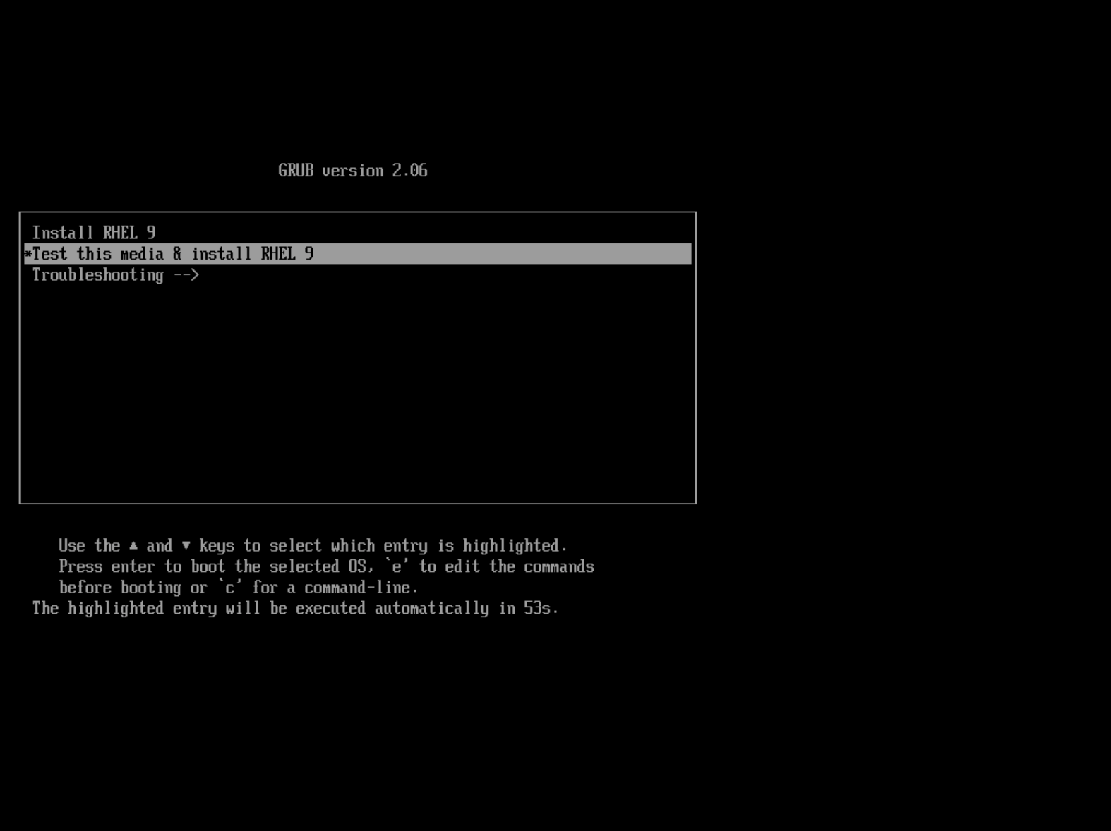
Figure: Select Install Option
- After the boot process completes, select your preferred language settings. Then click
Continue.
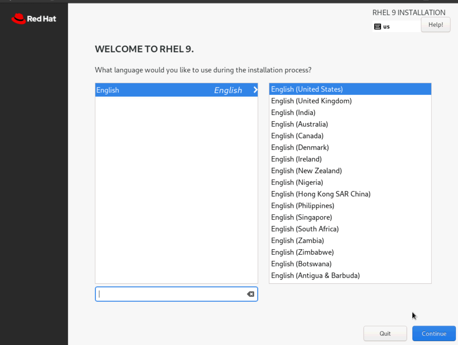
Figure: Select Language
- Select
Installation Destination.
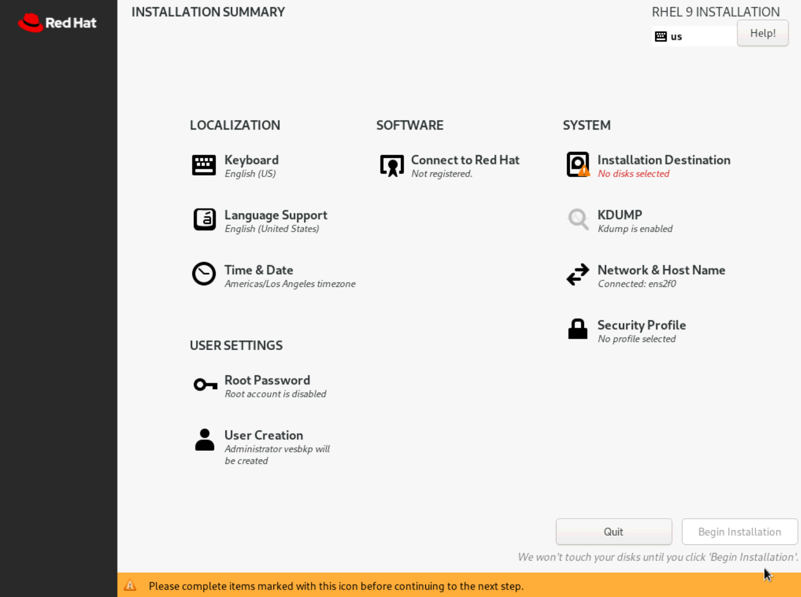
Figure: Select Language
- Select the disk to set as the installation destination, configure any additional settings, and then click
Done.
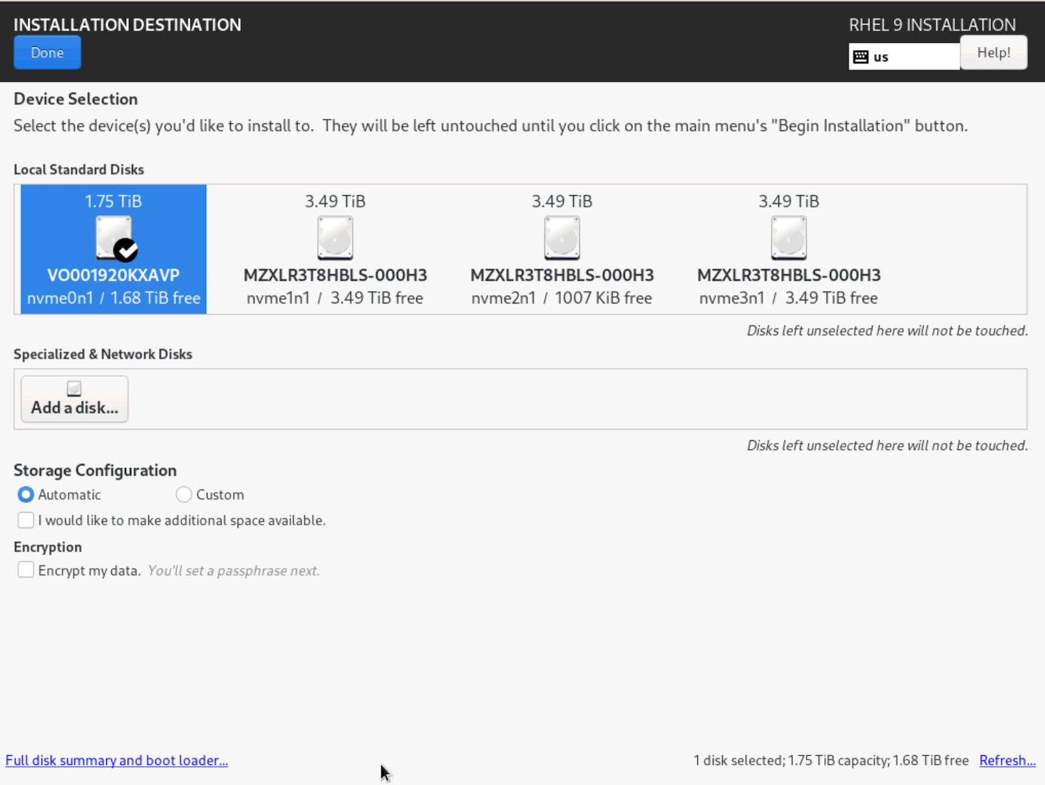
Figure: Select Language
- On the
INSTALLATION SUMMARYpage, clickBegin Installation.
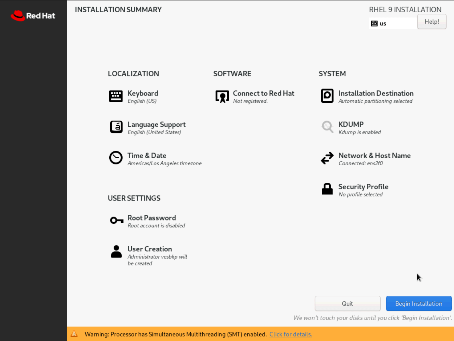
Figure: Select Language
- After the installation process completes, click
Reboot System.
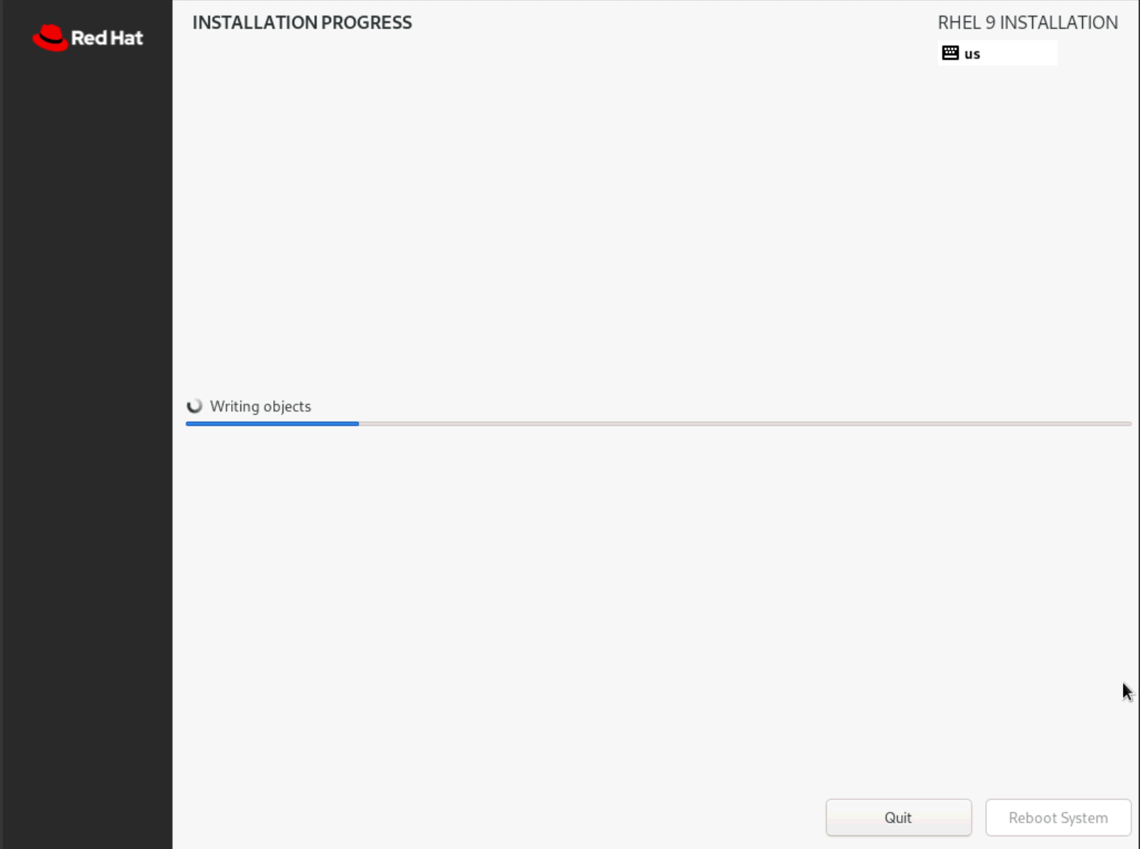
Figure: Select Language
Configure Node Parameters
Log in to the node to configure additional options.
Step 1: Log in to the node.
-
Access the node using SSH or through a console window.
-
Log in to the node with the default user credentials:
- Local user account:
admin - Password:
Volterra123
- Local user account:
-
If this is the first time you are logging in, you are prompted to update the default password for the
adminuser account. Follow the instructions to update the default password. -
Press the
Tabkey to select parameters to configure.
Step 2: Start optional network configuration.
You can optionally configure the network. Use this option if you want to use a static IP address instead of DHCP.
Use configure-network to perform the following tasks:
- Enable IPv6
- Configure static IP (need to reflect to configuration in UI)
- Special DNS, NTP, and so on
- Configure proxy
Note: You cannot change an IP address for a registered node in a multi-node Site. You must use fixed IP addresses or DHCP addresses with a fixed lease. When you configure an HTTP proxy server, IPsec tunneling is not supported. For tunneling, use SSL or automatic.
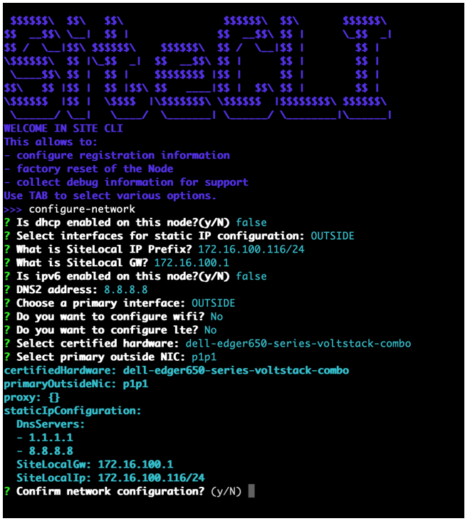
Figure: Configure network master-0
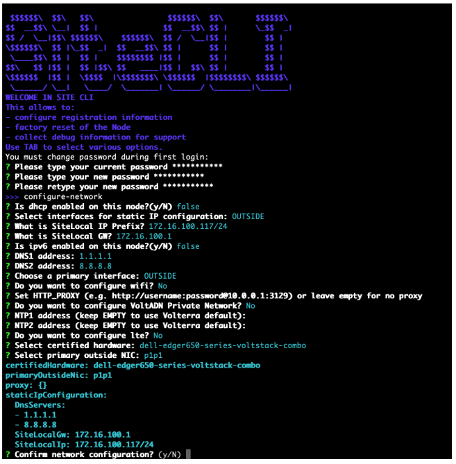
Figure: Configure network master-1
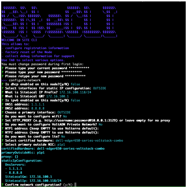
Figure: Configure network master-2
Step 3: Configure the main options.
Note: If you apply static configuration for the network, you must first perform network configuration using the
configure-networkoption before you set additional fields using theconfigureoption. Also, you cannot change the IP address of a node in a multi-node Site after the node is successfully registered.
Press the Tab key to select the configure option.
-
Enter the registration token.
-
Enter a CE Site name. This name must be the same as the name provided in the Distributed Cloud Console.
-
Enter a hostname. This is the node name.
Important: The name should not have "." in it. For example, the hostname can be node-0 or node0, but it cannot be node.f5.com since it is not supported. Your node name must adhere to DNS-1035 label requirements. This means the name must consist of lower case alphanumeric characters or “-“, start with an alphabetic character, and end with an alphanumeric character.
If configuring a multi-node Site, each node hostname must be unique.
-
Enter the longitude and latitude information.
-
Select an option for the certified hardware.
-
Configure any other options that are presented.
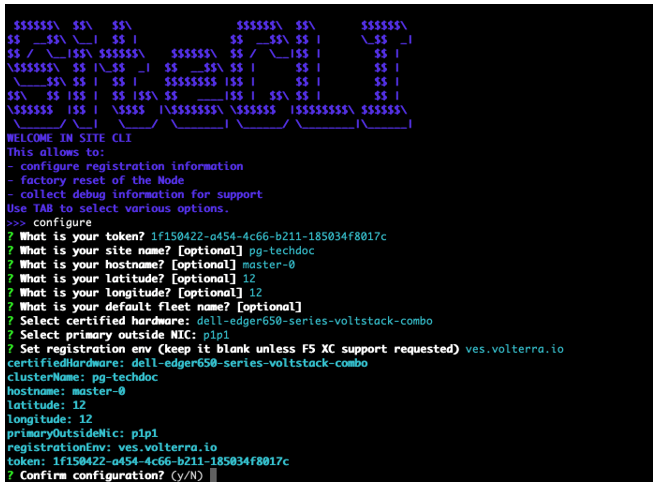
Figure: Configure master-0
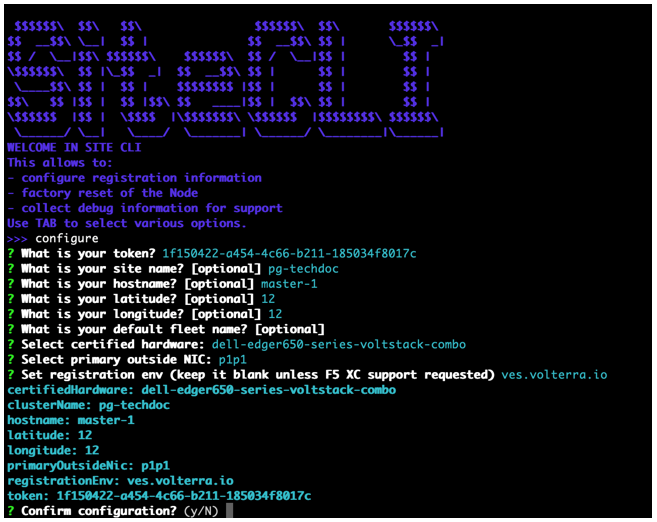
Figure: Configure master-1
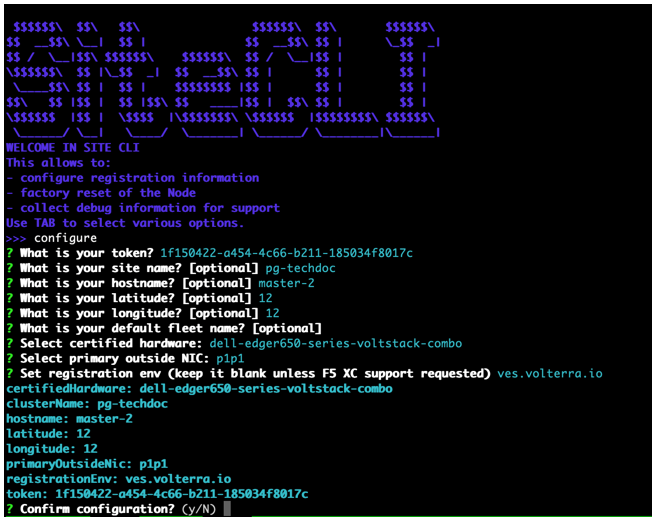
Figure: Configure master-2
Step 4: Confirm configuration.
Enter Y to confirm configuration. This triggers the registration process on Distributed Cloud global controllers.
Step 5: Verify the configuration.
-
Select
get config. -
Confirm that the settings are correct.
-
Wait a few minutes for the Site to be ready for registration.
- Optionally, select the
factory-resetoption to perform a configuration reset and repeat the registration process again per the instructions above.
-
If you use an NTP server, ensure that the server is reachable. Otherwise, leave the NTP server configuration empty so that the F5 Distributed Cloud NTP servers are used instead.
-
Use the
qkey to exit the health information page.
Register CE Site
After you install the F5 Distributed Cloud Services node, you must register it as a CE Site in the Distributed Cloud Console. For a multi-node CE Site, you must register each node.
Note: The USB allowlist is enabled by default. If you change a USB device, such as a keyboard after registration, the device will not function.
Register Multi-Node Site
Step 1: Navigate to the Site registration page.
-
Log into Console.
-
Click
Multi-Cloud Network Connect. -
Click
Manage>Site Management>Registrations.
Step 2: Accept the registration requests.
Registration requests are displayed in the Pending Registrations tab.
-
Click
Acceptto accept the registration requests from themaster-0,master-1, andmaster-2nodes. The node names will differ. -
Enter the same values for the following parameters for all the registration requests:
-
In the
Cluster namefield, enter a name for the cluster. Ensure that all control nodes have the same name. -
In the
Cluster sizefield, enter3. Ensure that all control nodes have the same cluster size.
-
-
Enter all mandatory fields marked with the asterisk (
*) character. -
Click
Save and Exit.
Step 3: Check Site status and health.
It may take a few minutes for the Site health and connectivity score information to update.
-
Click
Overview>Infrastructure>Sites. -
Click on your Site name. The
Dashboardtab appears, along with many other tabs to inspect your Site. -
Click the
Site Statustab to verify the following:-
The
Update Statusfield has aSuccessfulvalue for theF5 OS Statussection. -
The
Update Statusfield has aSuccessfulvalue for theF5 Software Statussection. -
The
Tunnel statusandControl Planefields under theRE Connectivitysection haveupvalues.
-
Note: The factory reset functionality is not supported. To update a Site node, power off and then destroy it. Perform the same procedure as above.
Register Single-Node Site
Step 1: Navigate to the Site registration page.
-
Log into Console.
-
Click
Multi-Cloud Network Connect. -
Click
Manage>Site Management>Registrations.
Step 2: Accept the registration requests.
Registration requests are displayed in the Pending Registrations tab.
-
Click
Acceptto accept the registration request for the node. -
In the form that appears, enter all mandatory fields marked with the asterisk (
*) character. -
Enter latitude and longitude values if you did not previously.
-
Enter other configuration information, if needed.
-
Click
Save and Exit.
Step 3: Check Site status and health.
It may take a few minutes for the Site health and connectivity score information to update.
-
Click
Overview>Infrastructure>Sites. -
Click on your Site name. The
Dashboardtab appears, along with many other tabs to inspect your Site. -
Click the
Site Statustab to verify the following:-
The
Update Statusfield has aSuccessfulvalue for theF5 OS Statussection. -
The
Update Statusfield has aSuccessfulvalue for theF5 Software Statussection. -
The
Tunnel statusandControl Planefields under theRE Connectivitysection haveupvalues.
-
Note: The factory reset functionality is not supported. To update a Site node, power off and then destroy it. Perform the same procedure as above.
Access CE Site Local UI
After you create and register your Site, you can access its local user interface (UI) to perform certain configuration and management functions. For more information, see Access Site Local User Interface.
Concepts
On this page:
- Objective
- Prerequisites
- Restrictions
- Minimum Hardware Requirements
- Supported Hardware
- Edge Hardware
- Server Hardware
- Create CE Site
- Prepare Bootable USB
- Configure the BIOS
- Install the Node OS Software
- Configure Node Parameters
- Register CE Site
- Register Multi-Node Site
- Register Single-Node Site
- Access CE Site Local UI
- Concepts