Create Virtual Network
Objective
This guide provides instructions on how to create a Virtual Network using the guided wizard in F5® Distributed Cloud Console (Console). For more information on a site, see Site.
A Virtual Network is an isolated L3 network. A Virtual Network can contain one or more IP subnets. Network elements in a virtual network (interface, host, listener, etc.) can talk to each other directly.
Two virtual networks can have overlapping IP address spaces. If two networks are connected directly, then they will have to guarantee unique IP addressing.
A Virtual Network is also used to configure static routes, either to inject and advertise them via Border Gateway Protocol (BGP), or to statically route to specific networks from this Virtual Network.
Using the instructions provided in this guide, you can create a Virtual Network and set up a static route from this network.
Prerequisites
The following prerequisite applies:
- An F5® Distributed Cloud Services Account. If you do not have an account, see Getting Started with Console.
Configuration
The following video shows the virtual network configuration:
Create a Virtual Network
Perform the following steps:
Step 1: Start virtual network object creation.
-
Log into Console.
-
Click
Multi-Cloud Network Connect.
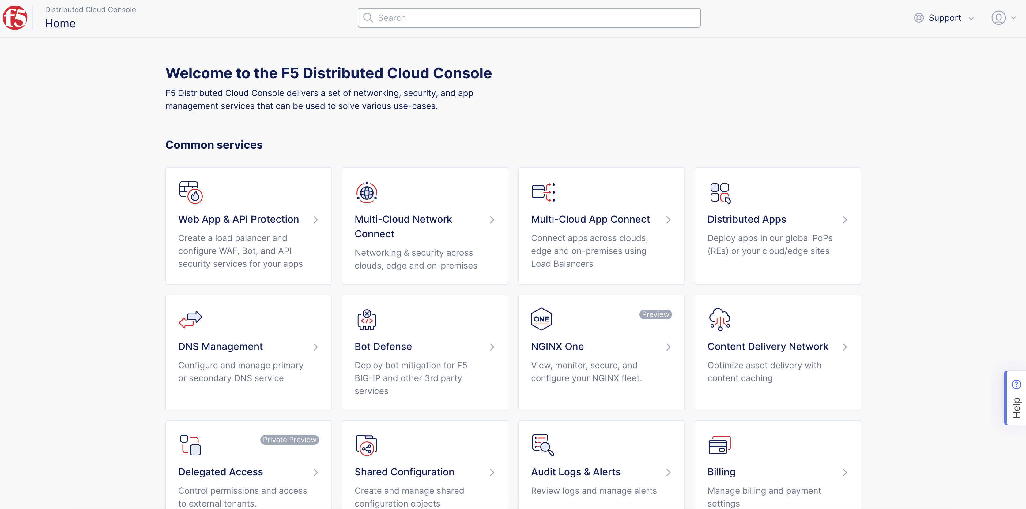
Figure: Console Homepage
- Select
Manage>Networking>Virtual Networks.
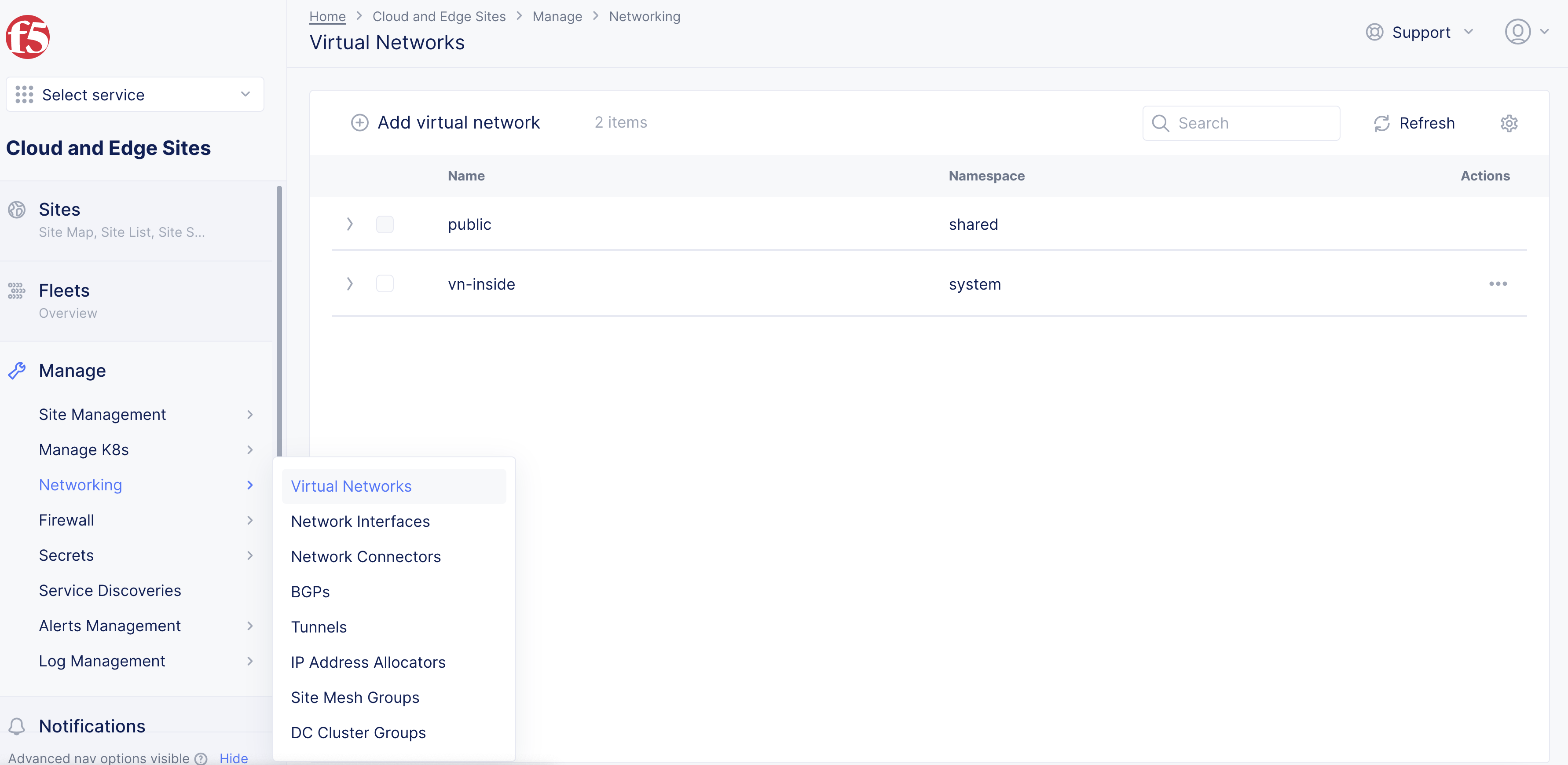
Figure: Virtual Networks
- Click
Add virtual network.
Step 2: Configure virtual network.
-
In the
Namefield, enter the name for the virtual network object. -
In the
Labelsfield, optionally select a key-value pair for the object. -
From the
Select Type of Networkdrop-down menu, select the network type that this virtual network object belongs to:-
Global Network: Network to extend to other sites, like L3 virtual routing and forwarding (VRF). -
Site Local (Outside) Network: Your outside network. -
Site Local Inside Network: Your inside network.
-
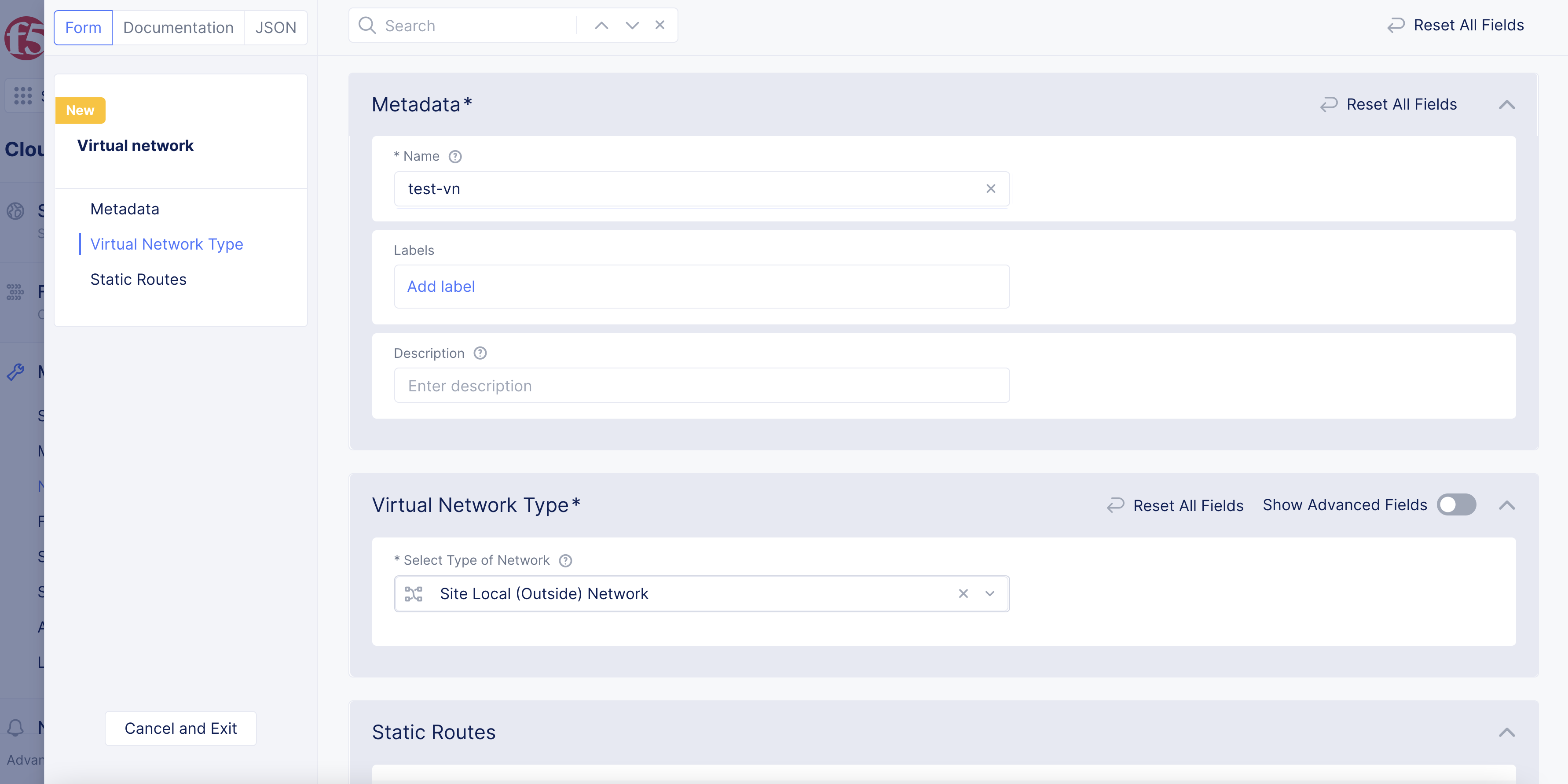
Figure: Virtual Network Configuration
-
Under the
Static Routessection, clickAdd Itemto configure a new static route for this virtual network:-
In the
List of IP Prefixesfield, enter a valid IPv4 IP prefix. -
From the
Select Type of Next Hopdrop-down menu, select the type of next hop for your router. The options include:-
IP Address: The traffic matching the IP prefixes is sent to the IP address. You must enter a valid IP address to send the traffic to in theIP Addressfield. -
Interface: The traffic matching the IP prefixes is sent to the interface. You must select an interface from the options in theInterfacedrop-down menu. -
Default Gateway: The traffic matching the IP prefixes is sent to the default gateway.
-
-
Optionally, select any attribute from the
Attributesdrop-down menu. -
Click
Add Item.
-
-
After you finish, click
Save and Exit.
Step 3: View the virtual network object information.
Click > to view the virtual network object's JSON data.
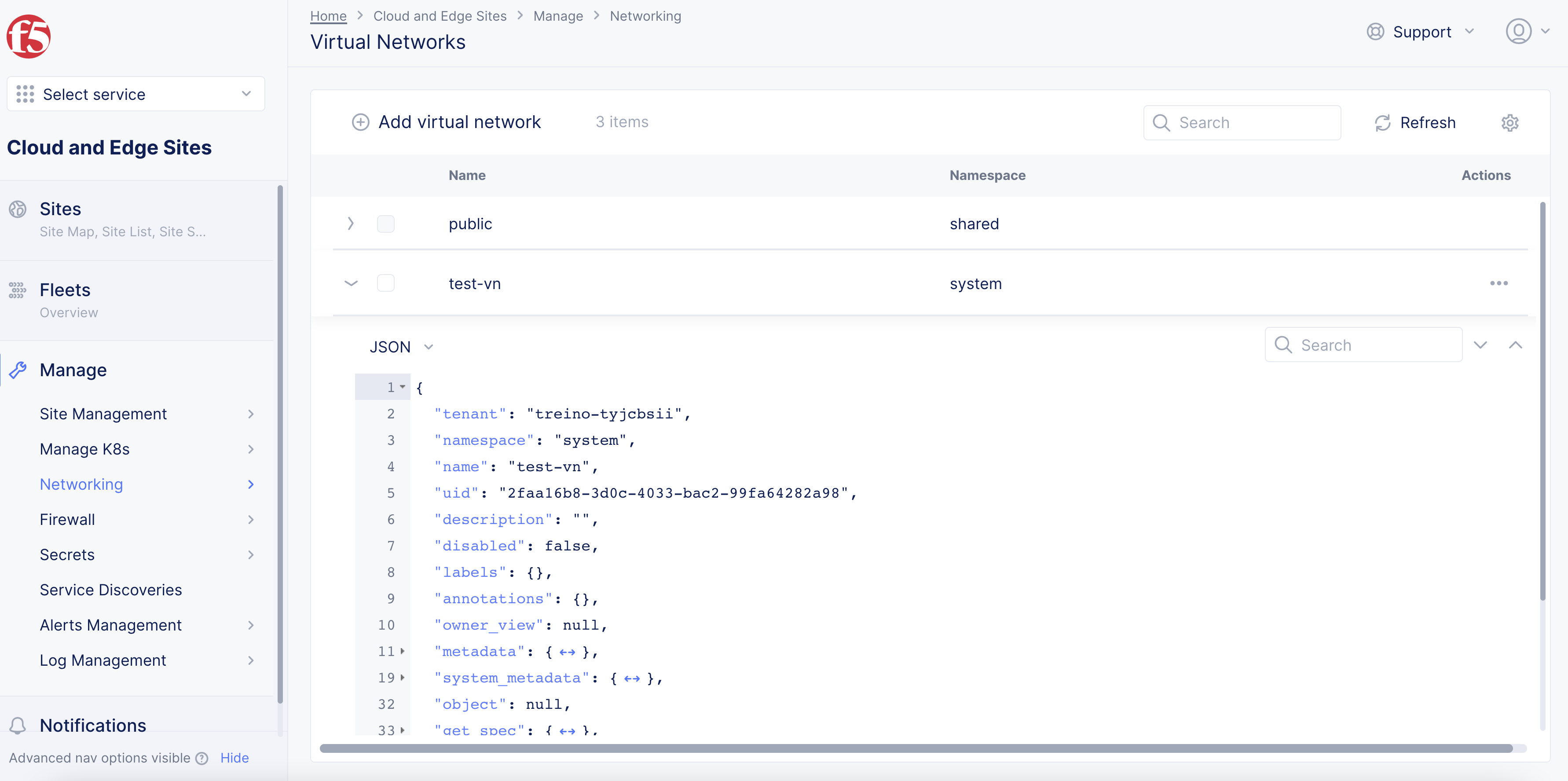
Figure: View Virtual Network Object Information