Create Network Interface
The following information explains how to create a network interface in the F5 Distributed Cloud Console and apply it to your Distributed Cloud Services Customer Edge (CE) Sites.
You can configure the following options in the network interface object:
- IP address allocation scheme of the network interface (DHCP client or server)
- Virtual Network of this network interface
- Whether to run a DHCP server on this network interface:
- Subnet to use for allocation
- Default gateway
- DNS server
- Reservations
When DHCP address assignment (server) is enabled in the Network Interface, external clients can get their addresses assigned from the configured subnet. The local interface can also get a dynamic address from the same pool if the DHCP client is enabled in the Network Interface. Gateway and DNS servers for such clients can be external addresses or addresses internally allocated from the same subnet, or they may be disabled.
Prerequisites
The following prerequisites apply:
- You must have a Distributed Cloud Services account. If you do not have an account, see Getting Started with the Distributed Cloud Console.
- You must have at least one site configured in Distributed Cloud Services.
Create a Network Interface
Use the following instructions to create and configure a new network interface object and apply it to your Distributed Cloud Services Customer Edge (CE) Sites.
-
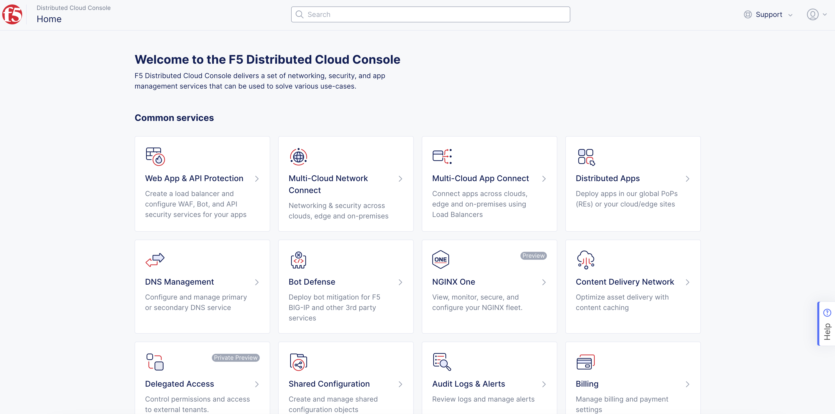
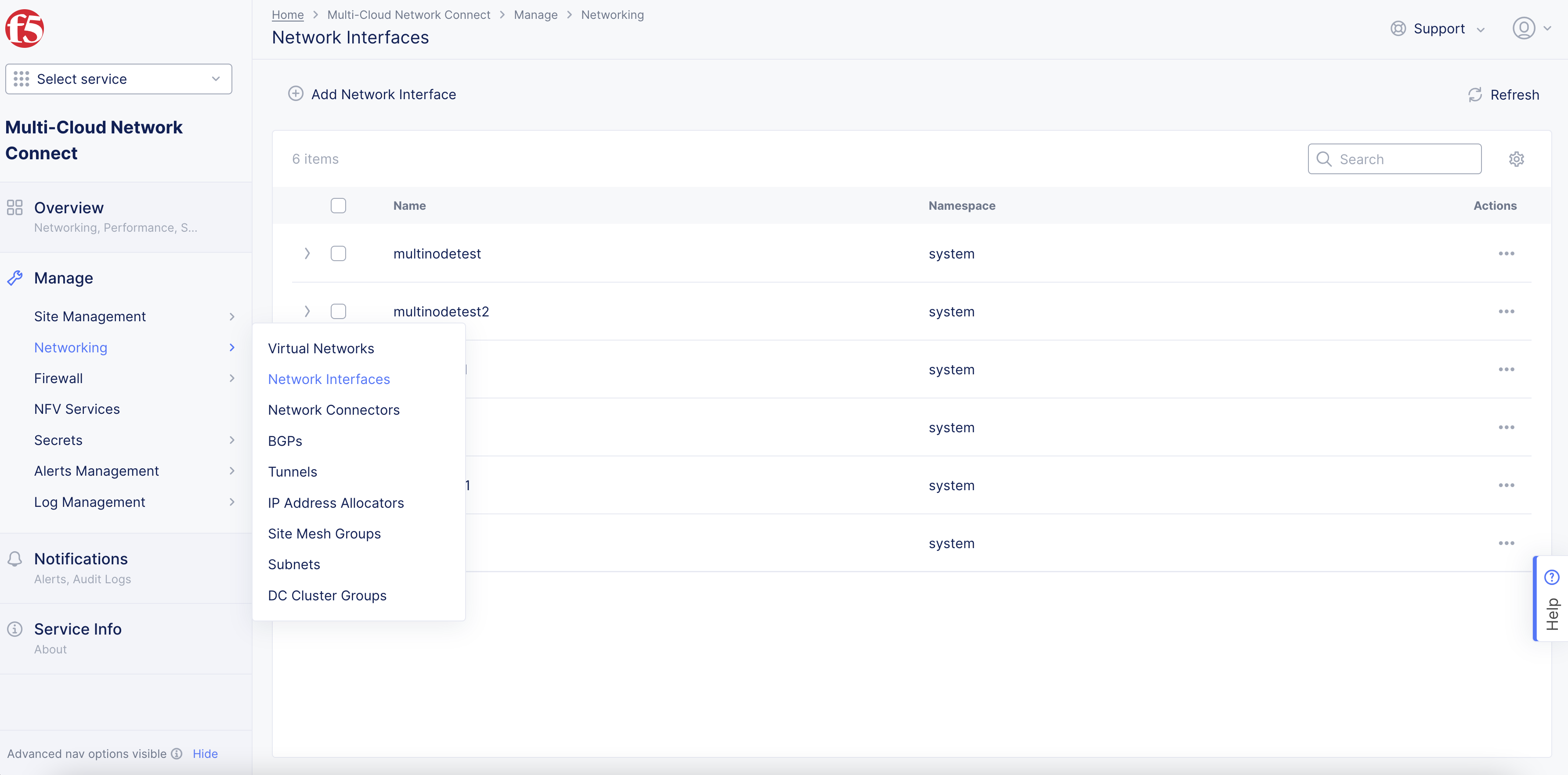
Log into the Distributed Cloud Console, and select Multi-Cloud Network Connect.

Figure: Console Homepage
-
Select Manage > Networking > Network Interfaces.
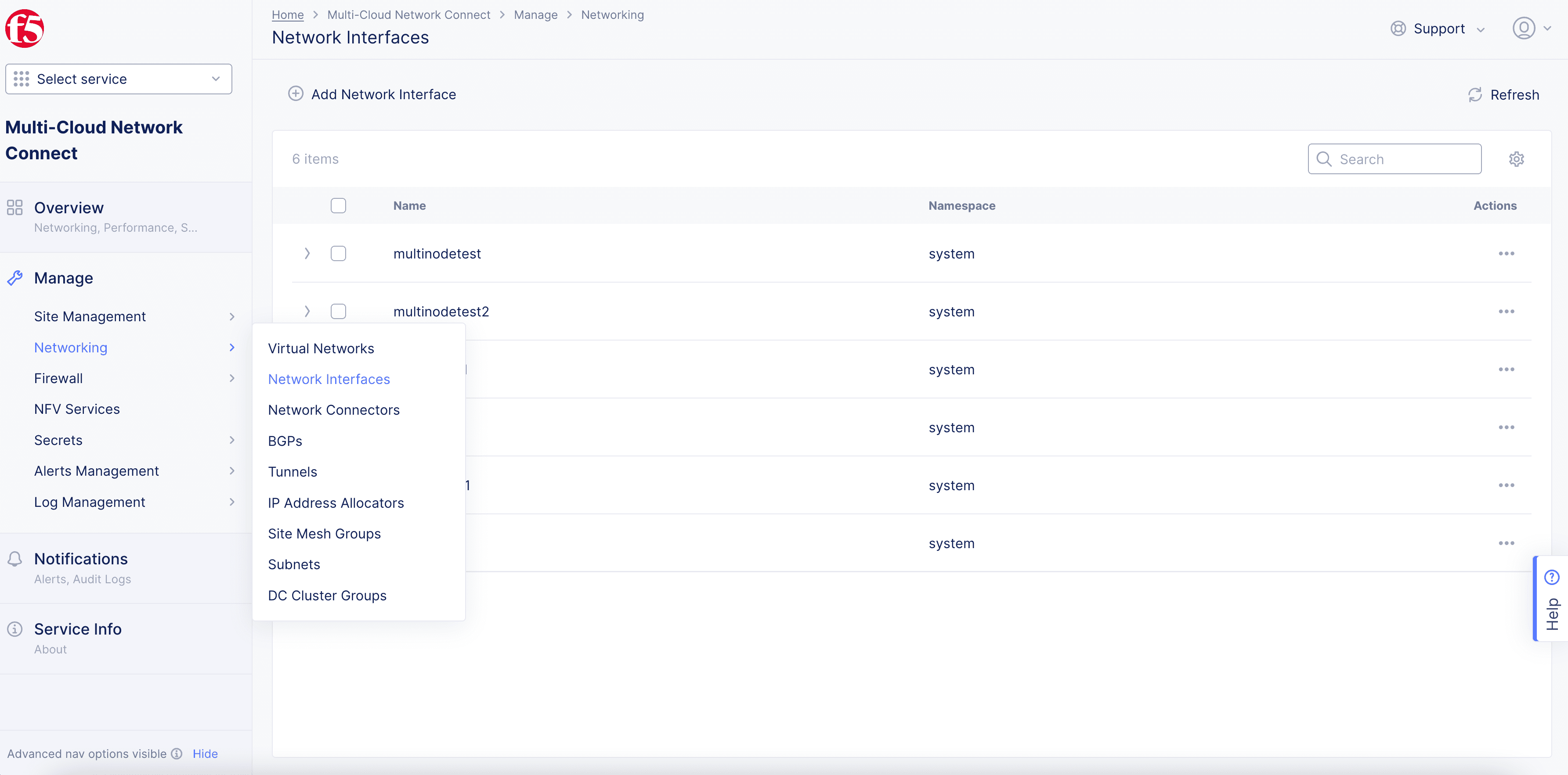
Figure: Network Interface Path
-
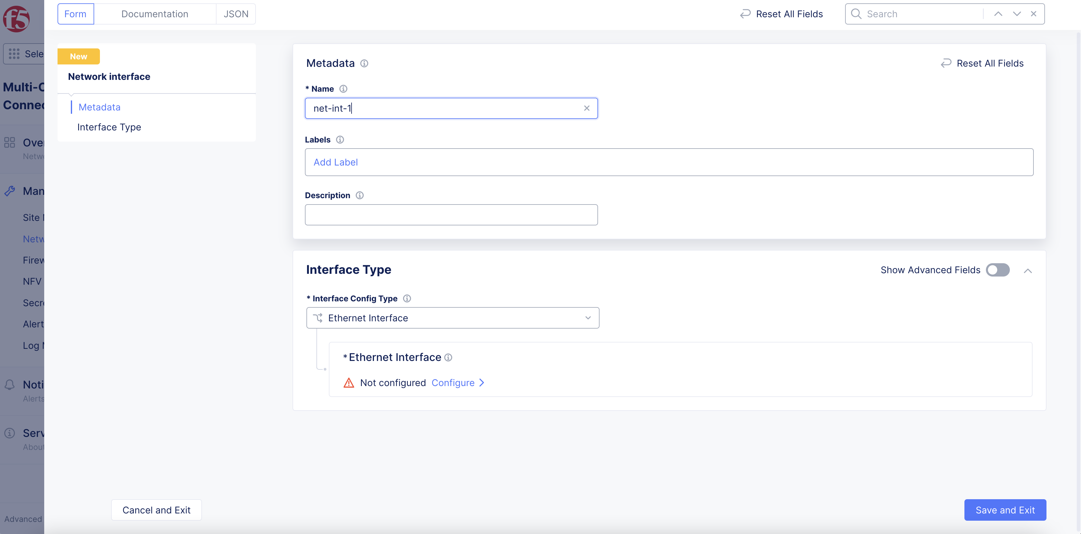
Select Add Network Interface.
-
Enter a Name and Description to identify the new network interface.
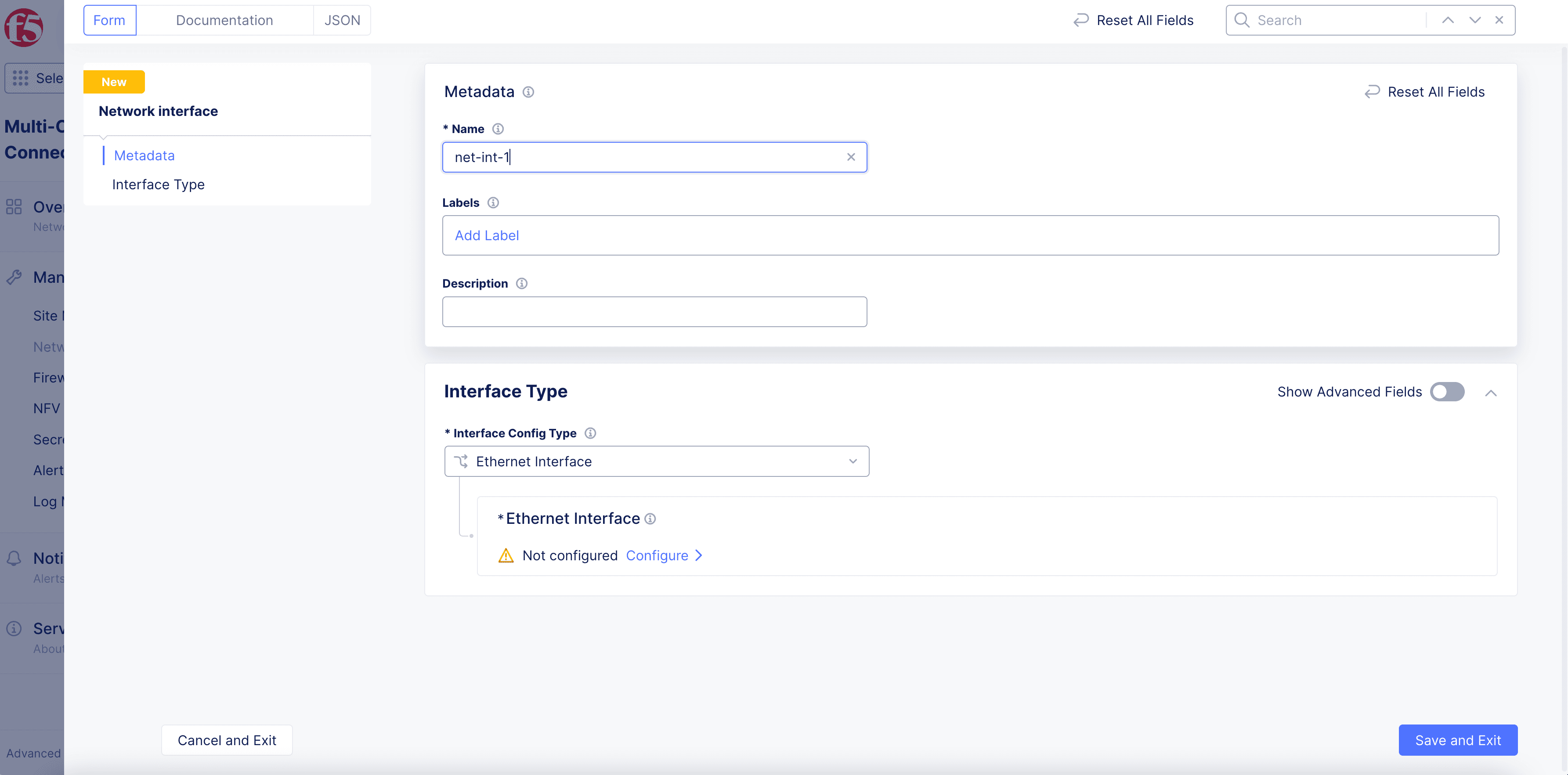
Figure: Network Interface Creation
-
From the Interface Config Type drop-down menu, select one of the following interface types.
- Ethernet Interface
- Dedicated Interface
- Tunnel Interface
- Dedicated Management Interface
- Layer2 Interface
To finish configuring your network interface, see the following information for the interface type you selected.
Ethernet Interface
-
From the Interface Config Type drop-down menu, select Ethernet Interface, and then select Configure.
-
From the Ethernet Device drop-down menu, enter an interface name, or select to See Suggestions, and choose an interface from the list.
-
From the Select Configuration for Cluster or Specific Node drop-down menu, select whether the interface device applies to Cluster, All Nodes in the Site or to a Specific Node. For a Specific Node, enter a node name or select to See Common Values, and choose a node from the list.
-
From the Select Untagged or VLAN tagged drop-down menu, specify if this interface is Untagged, or enter a VLAN Id.
-
In the IP Configuration section, from the Select Interface Address Method drop-down menu, select one of the following interface address methods:
-
DHCP Client: The interface is assigned an IP address from an external DHCP server.
-
DHCP Server: Select Configure to configure DHCP server settings:
-
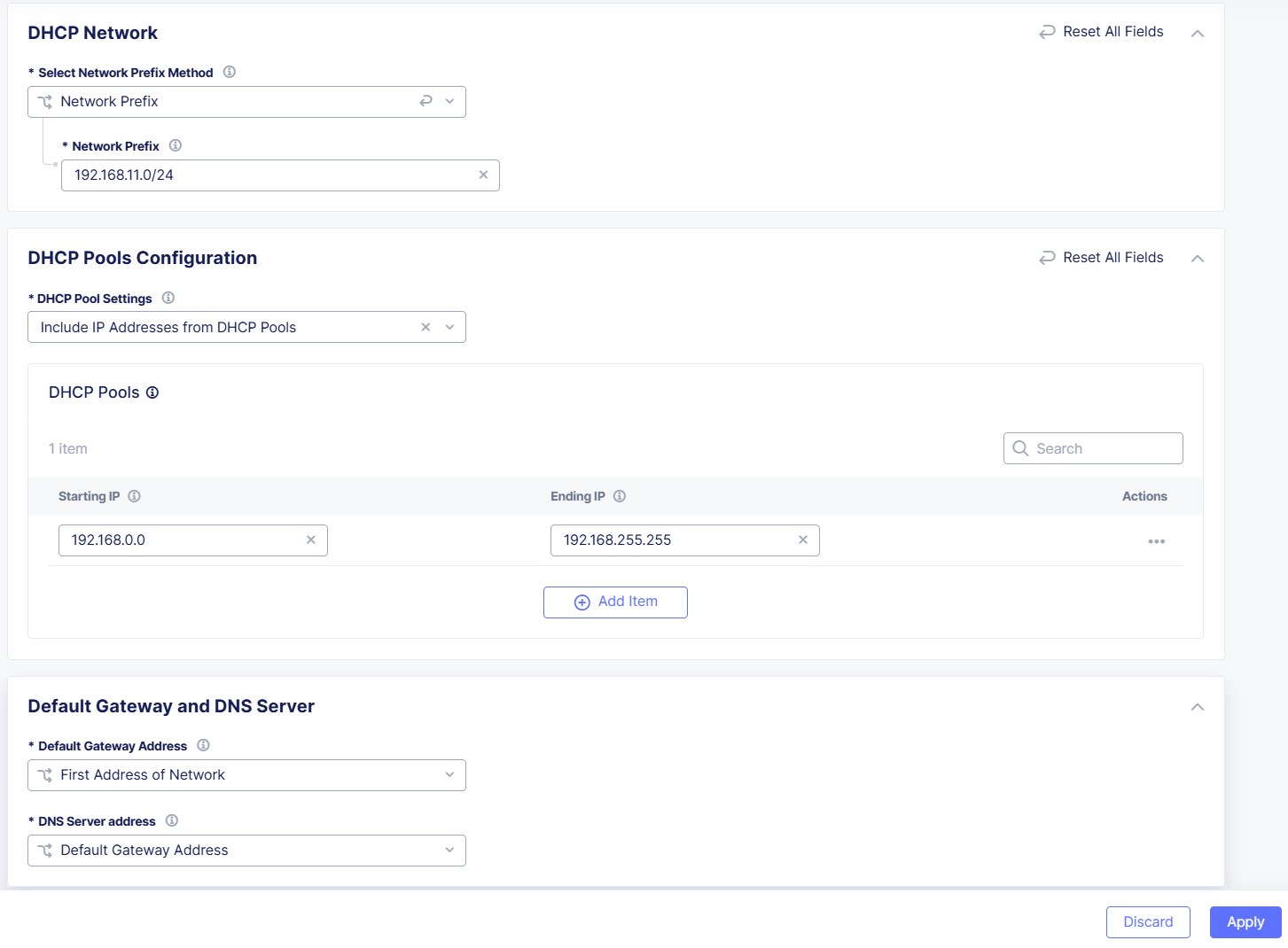
In the DHCP Networks, Pools, Gateway section, select Configure.
-
In the Network Prefix field, enter a prefix for a single site. For example:
192.168.11.0/24. -
From the DHCP Pool Settings drop-down menu, select whether to include or exclude the DHCP IP address ranges.
-
In the DHCP Pools section, select Add Item to add non-overlapping IP address ranges to the DHCP Pools list.
-
From the Default Gateway Address drop-down menu, select how the default gateway address is determined:
- First Address of Network: First IP address from the network prefix you configured.
- Last Address of Network: Last IP address from the network prefix you configured.
- Static IPv4 Configuration: Enter a specific IPv4 value from the network prefix to use as the default gateway. This must be a valid IP address within the network you defined in the network prefix section.
-
From the DNS Server address drop-down menu, select how the default DNS server address is determined:
- Default Gateway Address: DNS server address is the same as the default gateway address.
- Static IPv4 Configuration: Enter a specific IPv4 value from the network prefix to use as the DNS server.
-
Select Apply.

Figure: DHCP Server Configuration
-
In the Interface IPv4 Address Assignment for Site Nodes section, from the Select Interface Addressing drop-down menu, select how interfaces on each node are assigned local IP addresses:
- Automatic Start: An address is automatically assigned from the start of the first network in the list.
- Automatic End: An address is automatically assigned from the end of the first network in the list.
- Static IPv4 Configuration: Select Show Advanced Fields to display this menu option. Then select Add Item and enter the Node name and the IPv4 Address you want to assign to the node. The IP address must be from the networks defined in the DHCP server network prefix.
-
In the Fixed IPv4 Assignments for External Clients section, select Add Item.
-
In the MAC Address field, enter the MAC address for the DHCP client.
-
In the IPv4 Address field, enter the IP address you want to assign to the DHCP client.
-
When finished, select Apply.
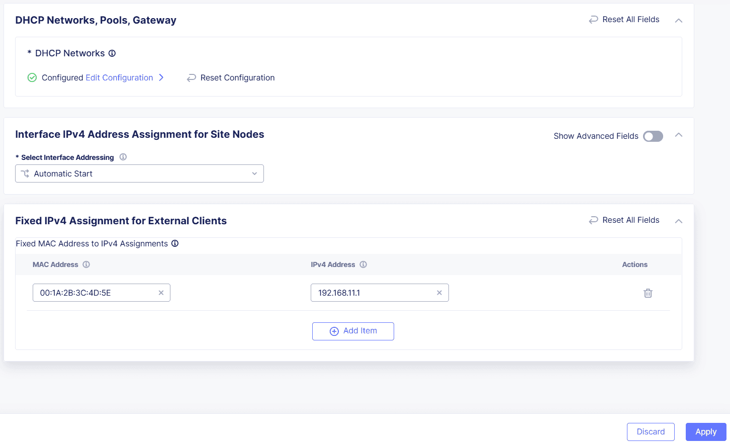
Figure: Configure IP Address Assignment
-
-
Static IP: From the Select Static IP Configuration drop-down menu, select one of the following options:
-
Specific Node: Enter the IP address and Prefix Length of the new Ethernet interface, and then enter the IP address of the Default Gateway.
-
Cluster, All Nodes of the Site: Enable Show Advanced Fields to display this menu option, and then select Configure.
- Select Add Item, enter an IP address for the site Node, and then select Configure.
- Enter an IP address/Prefix Length, and then enter the Default Gateway.
- Select Apply, and then select Apply again.
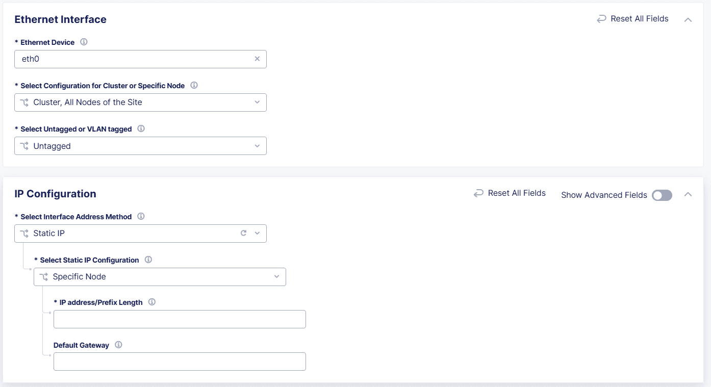
Figure: Configure Static IP as Interface Address Method
-
-
-
In the Virtual Network section, from the Select Virtual Network drop-down menu, select one of the following options:
- Site Local Network (Outside): The interface belongs to a site local network (outside).
- Site Local Network Inside: The interface belongs to a site local network inside.
- Segment: The interface belongs to a network segment. Select the Segment.
- Storage Network: Enable Show Advanced Fields to display this option. The interface belongs to a site local network inside.
-
(Optional) In the Common Configuration section, enable Show Advanced Fields, and then configure the following options:
- Maximum Packet Size (MTU): Enter a value for the maximum packet transfer size. The value must be between
512-16384. - Priority: Enter the priority of the network interface when multiple network interfaces are present in an outside network. Higher values are given higher priority. For example, an interface with priority set to
2is a higher priority than an interface with a priority set to1. - Select Link Quality Monitoring configuration: Select whether to enable quality probing for the interface.
- Maximum Packet Size (MTU): Enter a value for the maximum packet transfer size. The value must be between
-
From the Select Primary Interface drop-down menu, select whether the new Interface is Primary or that the Interface is Not Primary.
-
Select Apply, and then select Add Network Interface.


Dedicated Interface
-
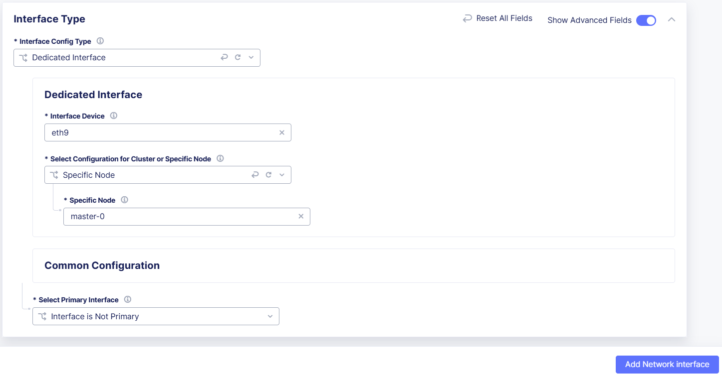
From the Interface Config Type drop-down menu, select Dedicated Interface.
-
In the Interface Device field, enter the name of the device for which the interface is configured, or select to See Common Values, and choose a device from the list. Use wwan0 for 4G/LTE.
-
From the Select Configuration for Cluster or Specific Node drop-down menu, select whether the interface device applies to Cluster, All Nodes in the Site or to a Specific Node. For a Specific Node, enter a node name or select to See Common Values, and choose a node from the list.
-
From the Select Primary Interface drop-down menu, select whether the new Interface is Primary or that the Interface is Not Primary.
-
Select Add Network Interface.

Figure: Configure Dedicated Interface
Tunnel Interface
-
In the Interface Type section, enable Show Advanced Fields.
-
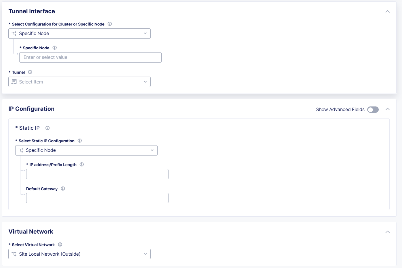
From the Interface Config Type drop-down menu, select Tunnel Interface and select Configure.
-
From the Select Configuration for Cluster or Specific Node drop-down menu, select Specific Node. For a Specific Node, enter a node name or select to See Common Values, and choose a node from the list.
-
From the Tunnel drop-down menu, select the tunnel you want to use with this interface.
-
In the IP Configuration section, from the Select Static IP Configuration, drop-down menu, select one of the following options:
- Specific Node: Enter the IP address and Prefix Length of the new Ethernet interface, and then enter the IP address of the Default Gateway.
- Cluster, All Nodes of the Site: Enable Show Advanced Fields to display this menu option, and then select Configure.
- Select Add Item, enter an IP address for the site Node, and then select Configure.
- Enter an IP address/Prefix Length, and then enter the Default Gateway.
- Select Apply. Then select Apply again.
-
In the Virtual Network section, from the Select Virtual Network drop-down menu, select one of the following options:
- Site Local Network (Outside): The interface belongs to a site local network (outside).
- Site Local Network Inside: The interface belongs to a site local network inside.
-
In the Common Configuration section, enable Show Advanced Fields, and then optionally configure the following options:
- Maximum Packet Size (MTU): Enter a value for the maximum packet transfer size. The value must be between
512-16384. - Priority: Enter the priority of the network interface when multiple network interfaces are present in an outside network. Higher values are given higher priority. For example, an interface with priority set to
2is a higher priority than an interface with a priority set to1.
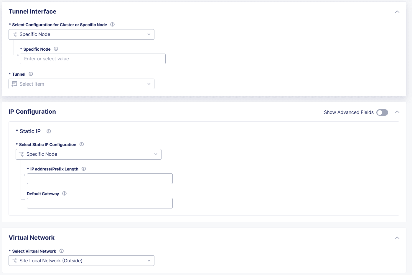
Figure: Configure Tunnel Interface
- Maximum Packet Size (MTU): Enter a value for the maximum packet transfer size. The value must be between
-
Select Apply, and then select Add Network Interface.
Dedicated Management Interface
- In the Interface Type section, enable Show Advanced Fields.
- From the Interface Config Type drop-down menu, select Dedicated Management Interface, and then select Configure.
- From the Interface Device menu, enter the name of the device for which the interface is configured, or select to See Common Values, and choose a device from the list.
- From the Select Configuration for Cluster or Specific Node drop-down menu, select whether the interface device applies to Cluster, All Nodes of the Site or to a Specific Node. For a Specific Node, enter a node name or select to See Common Values, and choose a node from the list.
- Optionally configure the Maximum Packet Size (MTU). Select Show Advanced Fields to display this option. Then enter a value for the maximum packet transfer size for the interface. The value must be between
512-16384. - Select Apply.
- After you finish, select Add Network Interface.
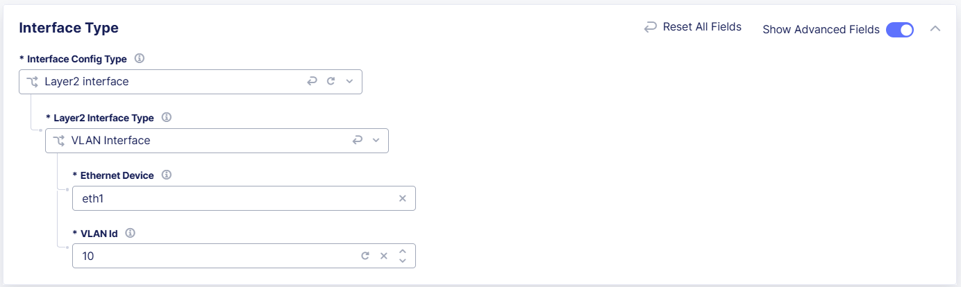
Layer2 Interface
- From the Interface Config Type drop-down menu, select Layer2 Interface.
- From the Layer2 Interface Type drop-down menu, select one of the following options:
- VLAN Interface:
- From the Ethernet Device menu, enter an Ethernet device name, or select to see See Common Values, and choose a device from the list.
- Enter a VLAN Id.
- VLAN on Site Local Outside Interface:
- Enter a VLAN Id.
- SR-IOV Interface:
- From the Ethernet Device menu, enter an Ethernet device name, or select to see See Common Values, and choose a device from the list.
- From the Select Untagged or VLAN tagged drop-down menu, specify if this interface is Untagged, or enter a VLAN Id.
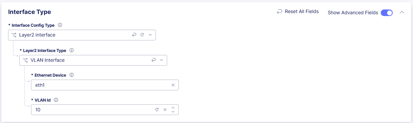
Figure: Configure Layer2 Interface
- VLAN Interface:
- Select Add Network Interface.