Deploy Palo Alto Networks Firewall Service
Objective
This guide provides instructions on how to insert a Palo Alto Networks VM-Series Firewall as a network functions virtualization (NFV) service in an AWS TGW site. For more information on F5® Distributed Cloud Services Sites, see Site.
Note: This NFV service feature is supported on AWS TGW Site.
Feature Overview
The use case for this feature is large enterprises that are expanding into public clouds and have standardized their operational model around their on-premises security appliance and wish to use the same appliance in the cloud mandated by their SecOps department. F5 Distributed Cloud now allows integration of PAN Next-Generation Firewalls in an AWS TGW Site. It automates and orchestrates the deployment of a PAN firewall with mesh CEs in a services VPC. It provides the ability to define granular traffic steering policies using an enhanced firewall policy, with observability and monitoring.
Traffic Flow
The next sections describe how East-West and North-South traffic is handled using this feature.
East-West Traffic
In this case, the traffic coming from VPC 1 to VPC 2 is steered to the PAN firewall using the enhanced firewall rule with source filter selecting VPC 1 and destination filter as VPC 2 and next-hop as PAN service. This example assumes that the PAN firewall rule is to allow the traffic. The following image shows the topological view for spoke VPCs and services VPC, where the TGW Site and PAN service object are deployed.
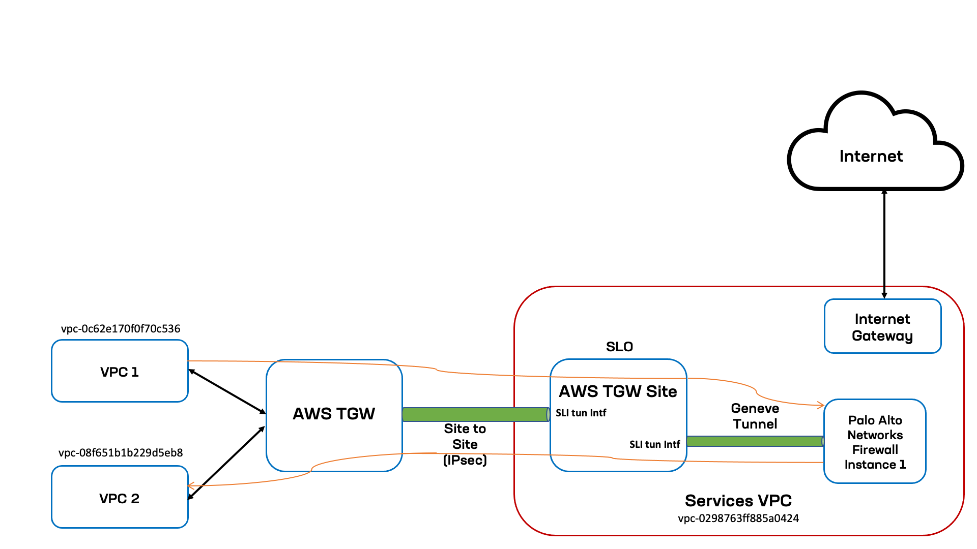
Figure: East-West Diagram
In this topology, the spoke VPCs VPC 1 and VPC 2 are identified by vpc-0c62e170f0f70c53 and vpc-08f651b1b229d5eb8 as the VPC IDs. The TGW Site and PAN firewall service are in the services VPC identified by vpc-0298763ff885a0424. And within the services VPC, the TGW Site and PAN firewall instance are connected using Geneve tunnel over the Site's Site Local Interface (SLI). The transit gateway is connected to the TWG Site using Site to Site VPN connection (also known as IPsec tunnels) terminating on the TGW Site's SLI.
The following list presents the sequence for East-West traffic flow (VPC 1 to VPC 2):
- Traffic sent from
VPC 1with destination inVPC 2network first lands on the transit gateway spoke route table. - Spoke route table has default route pointing to VPN connection of TGW site, the traffic is then sent to the TGW Site.
- Traffic is received on the TGW Site's SLI is evaluated for the enhanced firewall rules. The matching rule has action Insert PAN service for traffic from
VPC 1toVPC 2. The traffic is then sent to the Site's SLI connected to the PAN firewall instance. - The Site initiates a Geneve tunnel (adds the necessary TLV headers) toward the PAN firewall instance and then traffic is sent to the PAN firewall instance.
- The PAN firewall evaluates the traffic against matching rule, determines that the action is to allow the traffic to
VPC 2, and sends the traffic to the SLI of TGW Site over the Geneve tunnel. - The TGW Site inspects the received traffic, determines its next-hop as the SLI towards the transit gateway, sends traffic on the tunnel interface towards the TGW.
- Traffic will land on the hub TGW route table from where it has route to destination
VPC 2.
North-South Traffic
In this case, the traffic coming from the Internet to the Site Local Outside Internet VIP defined through the HTTP load balancer. Whenever such network type is selected on an HTTP load balancer, Distributed Cloud Services orchestrate an Internet facing AWS Network Load balancer. The traffic reaches the AWS network load balancer from where it will select the target group and route it to AWS TGW Site SLO interface. The Site then steers the traffic to the PAN firewall using the enhanced firewall rule with next-hop as PAN service. This example assumes that the PAN firewall rule is to allow the traffic. The following image shows the topological view for spoke VPCs and services VPC, where the TGW Site and PAN service object are deployed.
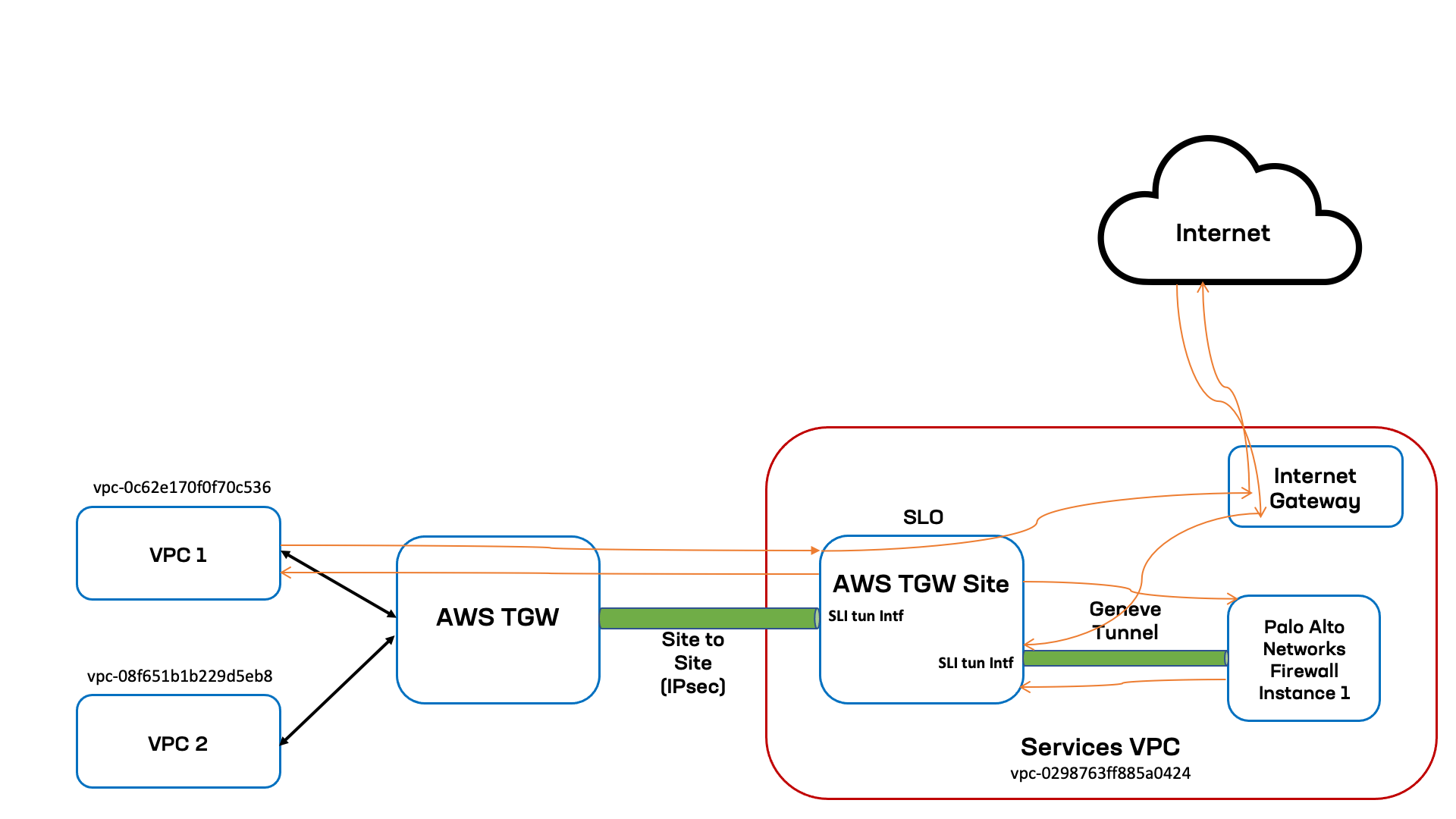
Figure: North-South Diagram
In this topology, the spoke VPC VPC 2 is identified by VPC ID vpc-08f651b1b229d5eb8. The TGW Site and PAN firewall service are in the services VPC identified by vpc-0298763ff885a0424. Within the services VPC, the TGW Site and PAN firewall instance are connected using Geneve tunnel over the Site's Site Local Interface (SLI). The transit gateway is connected to the TGW Site using IPsec tunnels terminating on the TGW Site's SLI.
The following list presents the sequence for East-West traffic flow (Internet to VPC1):
- Traffic sent from the Internet to the AWs Internet VIP lands on the AWS Internet facing network load balancer.
- From the load balancer it is routed to the AWS TGW Site SLO Interface.
- Traffic received on the TGW Site's SLO is evaluated for the enhanced firewall rule ACL. The rule will have next-hop as PAN firewall Service.
- The traffic is then forwarded to the PAN firewall instance over Geneve tunnel.
- The PAN firewall evaluates the traffic against matching rule, determines that the action is to allow the traffic to VPC1, and then sends the traffic to the SLI of TGW Site over the Geneve tunnel.
- The TGW Site then process the HTTP load balancer traffic and sends the traffic to origin server on
VPC 2over the tunnel interface toward the TGW. - Traffic will land on the hub TGW route table from where it has route to destination
VPC 2.
Note: The enhanced firewall rule can be applied using VPC ID or labels that identify the VPCs. Also, the enhanced firewall rules can evaluate traffic received on the TGW Site's Site Local OutSide (SLO) interface for Site-to-Site traffic and steer traffic as per the rule match. For example, traffic from source in a VNet connected to an Azure Site can be sent over the F5 Distributed Global Network to the SLO of the AWS TGW Site and the Site's firewall rules can allow, deny, or steer to the PAN firewall for further processing.
Prerequisites
-
A Distributed Cloud Services Account. If you do not have an account, see Create an Account.
-
An AWS TGW site.
-
A Palo Alto Networks account for managing the firewall.
Create NFV Service Object
In Console, create an NFV service object for the Palo Alto Networks VM-Series Firewall.
Step 1: Navigate to NFV services menu.
-
In
Multi-Cloud Network Connect, selectManage>NFV Services. -
Click
Add External Service.
Step 2: Configure NFV service object.
-
In the
Namefield, enter a name for this new NFV service. -
Optionally, click
Add Labelto group this object with others using a key-value pair. -
From the
External Service Providermenu, selectPalo Alto Networks VM-Series Firewall on AWS. -
Click
Configure.
Step 3: Configure firewall settings.
-
From the
Instance Typemenu, select the instance size for your deployed site. -
From the
AMI Choicemenu, select the Amazon Machine Image (AMI) of your firewall. -
Make a choice in the
Initial Setup Optionmenu. ForSetup Authorized Public SSH key, enter the public SSH for the user to access the node. ForAuto Setup API Access & Users, clickConfigure:-
Enter user given public and private SSH keys
-
In the
Private SSH keysection, clickConfigure.-
For a clear secret, enter it in the
Secretfield and selectTextorBase64to indicate the format of the secret. -
For an existing blindfold secret, the existing blindfold secret.
-
For a new blindfold secret, select either a built-in or custom secret, and then enter the secret.
-
Click
Applyto save it as the private SSH key.
-
-
Enter the
Firewall Admin Username. -
For the
Firewall Admin Password, clickConfigure.-
For a clear secret, enter it in the
Secretfield and selectTextorBase64to indicate the format of the secret. -
For an existing blindfold secret, the existing blindfold secret.
-
For a new blindfold secret, select either a built-in or custom secret, and then enter the secret.
-
Click
Applyto save it as the firewall admin password.
-
-
Click
Applyto save the auto setup API access and users configuration.
-
-
From the
AWS Transit Gateway Sitemenu, select the AWS TGW site from the list displayed.
Step 4: Configure firewall instance.
-
In the
AZ Nodessection, clickAdd Item. -
In the
Node Namefield, enter the name to use for the service nodes. -
From the
AWS AZ Namemenu, select the availability zone used with the region your AWS TGW site is deployed in. -
From the
Subnet for Mgmt Interfacemenu, select how you want to configure the subnet for the management interface. You can select from the following options:-
Autogenerate Subnet: Default option. The system will autogenerate this subnet for you. -
Specify Subnet: You can manually enter the subnet. You can use aNew SubnetorExisting Subnet ID.
-
-
Click
Apply.
Step 5: Optionally, connect firewall to Panorama.
Panorama is used to configure and manage your Palo Alto Networks VM-Series Firewall. You can configure one or more firewall VMs. By default, the firewall does not connect to Panorama. However, you can optionally choose to connect to it.
-
In the
Panorama Connectionsection, perform the following:-
From the
Panorama Connectionmenu, selectEnable connection from firewall to panorama. -
Click
Configure. -
In the
Server Ipv4 Addressfield, enter the IP address for the server the firewall will connect to. -
Under the
Authentication key for Panoramasection, clickConfigure. -
Configure your secret with
Blindfolded SecretorClear Secret. -
Click
Apply. -
Click
Apply.
-
-
Click
Applyto complete firewall configuration.
Step 6: Optionally, set node management based on HTTP.
-
From the
HTTPS Based Management of Nodesmenu, enable theHTTPS Based Managementoption. -
Enter a domain suffix in the
HTTPS Based Managementfield. This will be used along with theNode Nameset in the previous step to form the management URL for the node.
Note: Ensure that the domain is delegated to F5 Distributed Cloud Services. Default HTTPS port is 443 and Internet access is enabled by default.
- From the
Access on Site Local Networksmenu, select an option for the site local network. The default option isEnable Internet Access. For all other options, clickConfigure. In the form that appears, configure TLS settings, and then clickApply.
Note: For enabling both the East-West and North-South traffic, configure both inside VIP and outside VIP.
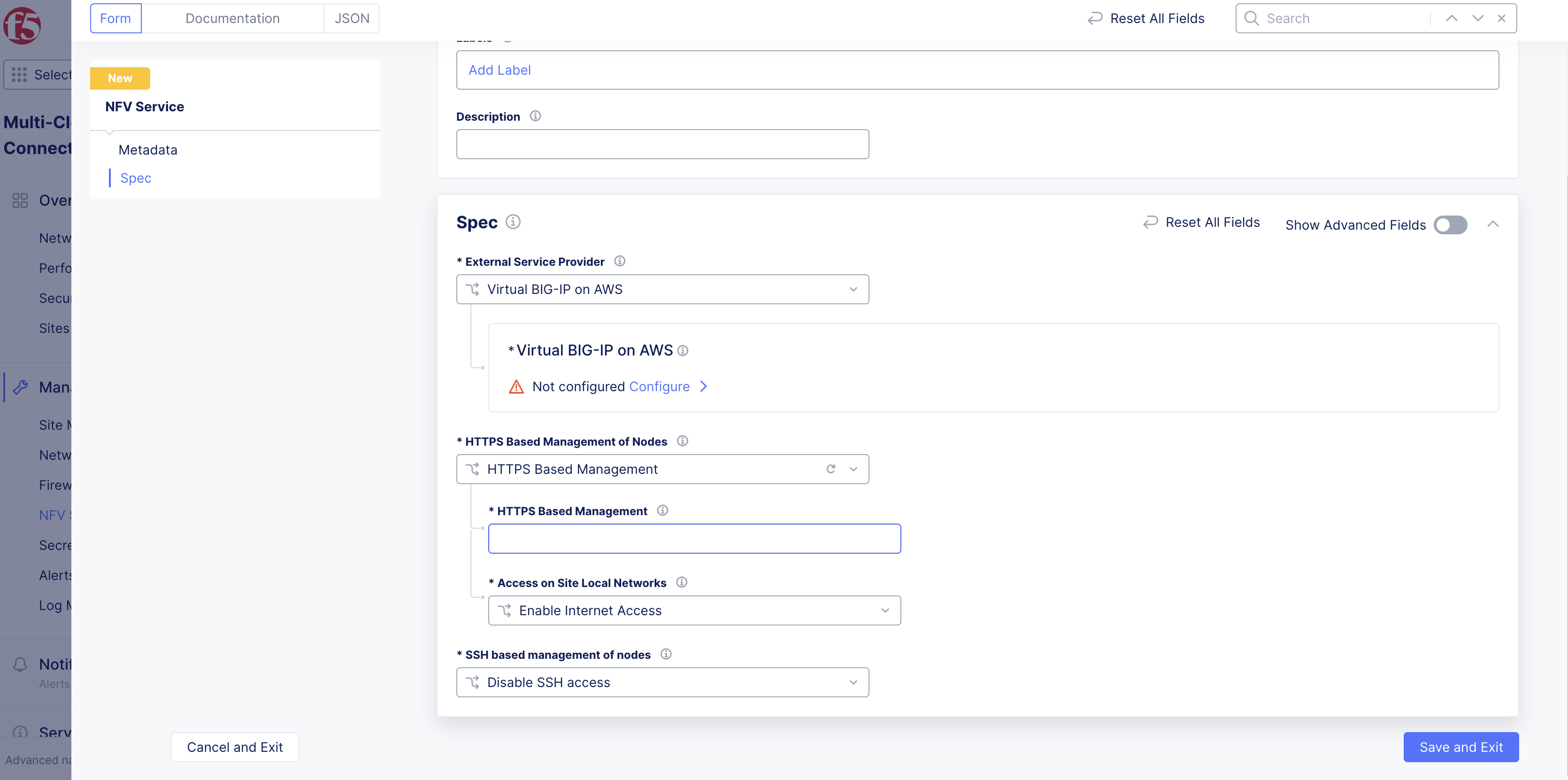
Figure: HTTP Based Node Management Settings
Step 7: Optionally, set node management based on SSH.
-
From the
SSH based management of nodesmenu, selectEnable SSH access to nodes. -
From the
Enable SSH access to nodesmenu, select an option for the site local network.
Note: It is recommended to use the default option of
Enable On Site Local Outside.
- Click
Add Item.
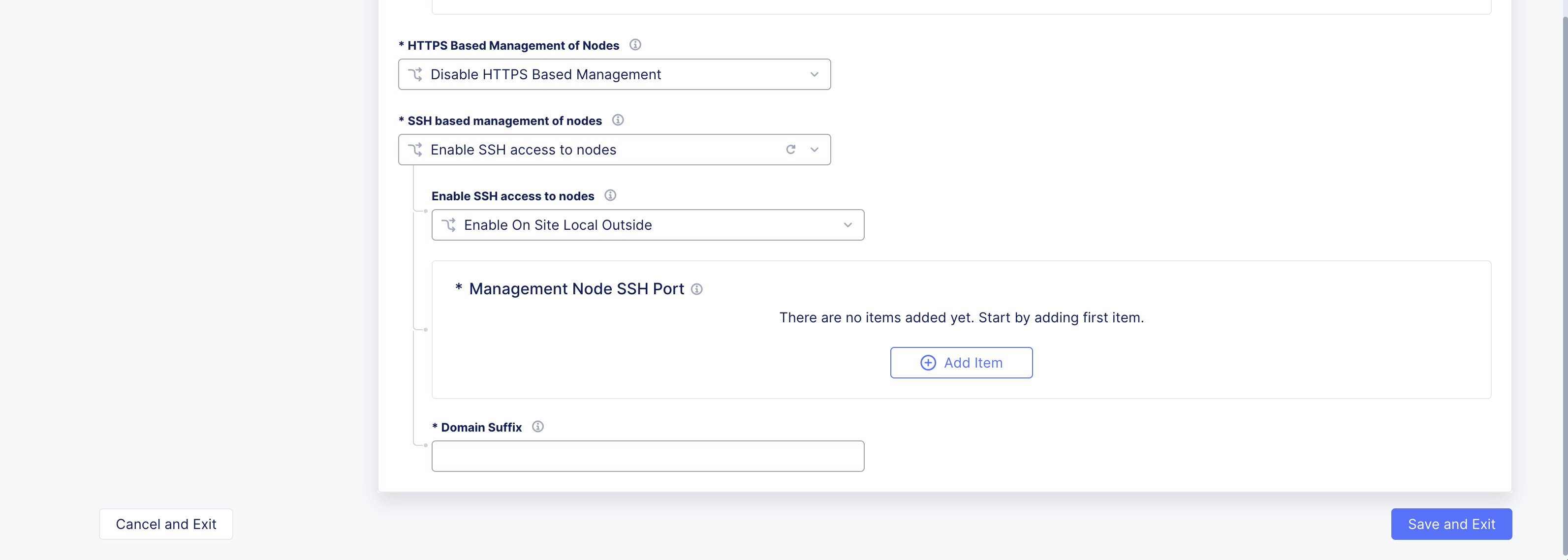
Figure: SSH Node Management
-
From the
Node Namemenu, select the node name to use for management. ClickSee Suggestionsto display a list. -
From the
SSH Portmenu, enter a TCP port number. -
Click
Apply. -
In the
Domain Suffixfield, enter a suffix value that will be used to generate the node hostname.
Step 8: Save firewall object.
-
Click
Save and Exit. -
To verify, navigate to
Overview>Security. In the dashboard, underService Instancessection, verify if the columns display the configuration previously set. It may take a few minutes for the items to appear.
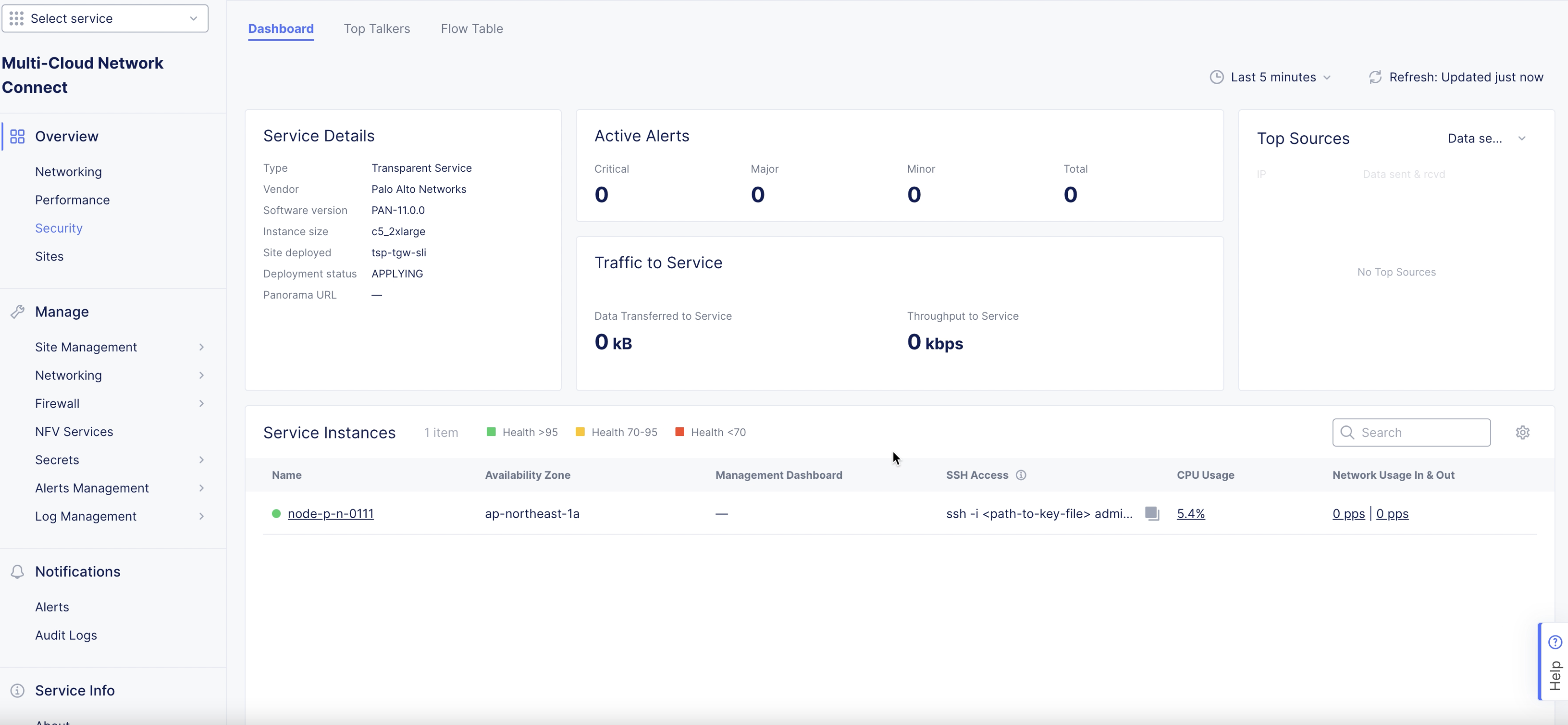
Figure: Verify Configuration
Create Enhanced Firewall Policy
An enhanced firewall policy enables you to create network level policies based on VPC tags, VPC IDs, IP, and IP prefix set object. The label selector option can also be used for selecting traffic coming from VPC-level tags, a global network, or interfaces. You can configure the enhanced firewall policy to allow, deny, or forward traffic to an NFV service.
The following steps provide instructions on creating an enhanced firewall policy to forward traffic to the Palo Alto Networks VM-Series Firewall (NFV service):
Step 1: Navigate to Enhanced Firewall Policies.
-
In
Multi-Cloud Network Connect, selectFirewall>Enhanced Firewall Policies. -
Click
Add Enhanced Firewall Policy. -
In the
Namefield, enter a name for the new enhanced firewall policy. -
From the
Select Enhanced Firewall Policy Rule Typemenu, selectCustom Enhanced Firewall Policy Rule Selection. -
Click
Configure. -
Click
Add Item.
Step 2: Create custom rule.
-
In the
Namefield, enter a name for this new rule. -
From the
Source Traffic Filtermenu, select an option to filter on source traffic. -
From the
Destination Traffic Filtermenu, select an option to filter on destination traffic. -
From the
Select Type of Traffic to Matchmenu, select the type of traffic to match to this new rule. -
From the
Actionmenu, select the action to take if traffic matches to this new rule. For the NFV service, selectInsert an External Service. -
From the
Select External Servicemenu, select the NFV services object previously created for the firewall. -
Click
Apply. -
Click
Apply.
Step 3: Save configuration.
Click Save and Exit.
Add Enhanced Firewall Policy to Site
After each enhanced firewall policy is created, you must add it to your site.
Step 1: Navigate to list of sites.
-
Navigate to the list of AWS TGW sites.
-
Find your site and click
.... -
Click
Manage Configuration>Edit Configuration.
Step 2: Add policy to site.
-
In the
Security Configurationsection, clickConfigure. -
From the
Manage Firewall Policymenu, selectActive Enhanced Firewall Policies. -
Click
Configure. -
From the list, select the enhanced firewall policy previously created for the NFV service.
-
Click
Apply. -
Click
Applyto add the firewall configuration.
Step 3: Save configuration.
Click Save and Exit.
Monitor Firewall Service
This section provides instructions on how to verify your PAN VM NFV service and to monitor instance metrics using F5 Distributed Cloud Console.
-
Navigate to
Multi-Cloud Network Connect>Overview>Security. -
Select your PAN VM. This page includes the
Dashboard,Top Talkers, andFlow Tabletabs. Also provided is basic service details, like vendor and software information and the URL for the management interface. You can also verify withDeployment statusset toAPPLIEDto confirm the PAN VM is successfully deployed. TheActive Alertssection provides details on security events, and theTop Sourcessection provides more information on specific locations interacting with the PAN VM. TheTraffic to Servicesection provides information on data rates flowing into the PAN VM. -
To locate the PAN FW instance's management IP, find the value displayed as
Panorama URLunder theService Details.
Figure: Dashboard
-
Toward the bottom of the page select the node instance to see specific metrics.
-
To log into your Panorama management account, click the link under
Management Dashboard. This opens a new tab so that you can log into Panorama.
Access PAN Virtual Machine Instance
You can log into your Panorama management account or use SSH to access the PAN VM instance.
To access the Panorama management account, click the link under the Management Dashboard column.
Accessing the PAN VM instance with SSH requires you to create a TCP load balancer with origin pool pointing to the PAN VM management interface IP. Perform the following to enable SSH access to PAN VM instance:
-
In the
Multi-Cloud App Connectservice, navigate toManage>Load Balancers>TCP Load Balancers. -
Click
Add TCP Load Balancer. -
Enter a name for the load balancer.
-
Enter a domain name in the
Basic Configurationsection. -
Under
Origin Pools, clickAdd Item. -
Create a new origin pool from the origin pools form. Add a name for your new origin pool.
-
In the
Origin Serverssection, clickAdd Itemto create a new origin server. -
From the
Select Type of Origin Servermenu, select thePublic IP of Origin Serveroption and then enter the PAN management IP. ClickApplyto add the origin server. ClickContinueto add the origin pool. -
Click
Apply. -
Click
Save and Exitto create the TCP load balancer. -
Access the domain in the TCP load balancer with SSH from a terminal.
Note: For more information, see TCP Load Balancer.