Deploy and Manage BIG-IP Service
Objective
This guide provides instructions on how to deploy and manage the F5 BIG-IP Virtual Edition (VE) service on your AWS TGW Site using F5® Distributed Cloud Services. For more information on the F5® Distributed Cloud Services Sites, see Site.
The F5 BIG-IP is a family of products covering software and hardware designed around application availability, access control, and security solutions. The instructions provided in this document cover deploying the BIG-IP software appliance acting as an application delivery controller using the F5 Distributed Cloud Services. For more information on BIG-IP products, see BIG-IP Products.
Using the instructions provided in this guide, you can deploy a BIG-IP virtual appliance on your AWS VPC, associate it with your AWS TGW Site, and set the VE appliance to control your application delivery.
Note: The network functions virtualization (NFV) service is supported only for the BIG-IP VE appliance on AWS TGW Site.
Design
Deploying the BIG-IP virtual appliances in AWS VPC requires deploying AWS TGW site with the VPC attachments, services VPC, and subnet configurations. Next, create BIG-IP VE service object, associated with a TGW site and launched as per the service node settings.
Note: Service node is an abstract term that takes the characteristics of the service that gets deployed in it. In this case, it is the BIG-IP service.
The images in the following sections show the reference topology for the BIG-IP deployment where BIG-IP service nodes deployed in AWS VPC provide Advanced Web Application Firewall (AWAF) functionality to workloads routed via TGW. More specifically as depicted in the images, requests made from an application in VPC (named – Shared) to an application in VPC (named - Dev) are processed by the BIG-IP service if the requests match the NFV service configuration. Similarly, requests from internet to an application in VPC are routed through the AWS network load balancer and through the TGW to BIG-IP service if requests match the NFV service configuration. The BIG-IP service then routes the request to the endpoint in VPC.
Note: Not all requests from Dev-VPC to Shared-VPC are processed by BIG-IP. Only the requests directed to the inside VIP as per NFV service configuration are processed by BIG-IP.
The hub, spoke, and services VPC route tables are programmed with the entries that define the traffic path for request and response.
Note: The AWS TGW workload subnet setting is different from the workload subnets in the attached VPC (shared VPC in the reference diagram). The workloads in the attached VPC represent applications that are routed via the BIG-IP service node. In this guide, the term workload subnets refer to the subnets in the attached VPC.
East-West Traffic
In this reference topology, an interface from TGW site is connected to the BIG-IP management interface and requests to the BIG-IP management address are routed through the same TGW Site interface. Here, the BIG-IP management interface is similar to a workload subnet interface from the point of view of TGW Site. The BIG-IP external interface is connected to the inside interface of the TGW site. Requests to the application are first forwarded to the TGW site inside interface using the spoke route table entries. The inside interface then forwards the traffic to the BIG-IP external interface over an IP-in-IP tunnel. The BIG-IP appliance then forwards the traffic to the origin server as per the programmed entries of services VPC route table. This is internally handled by the BIG-IP and routed to the subnets where the workloads are running.
The response from the workload subnet then received by BIG-IP is sent through BIG-IP external interface to the inside interface of the TGW site over the same IP-in-IP tunnel. The traffic is then forwarded to the requestor subnet using the programmed hub route table.
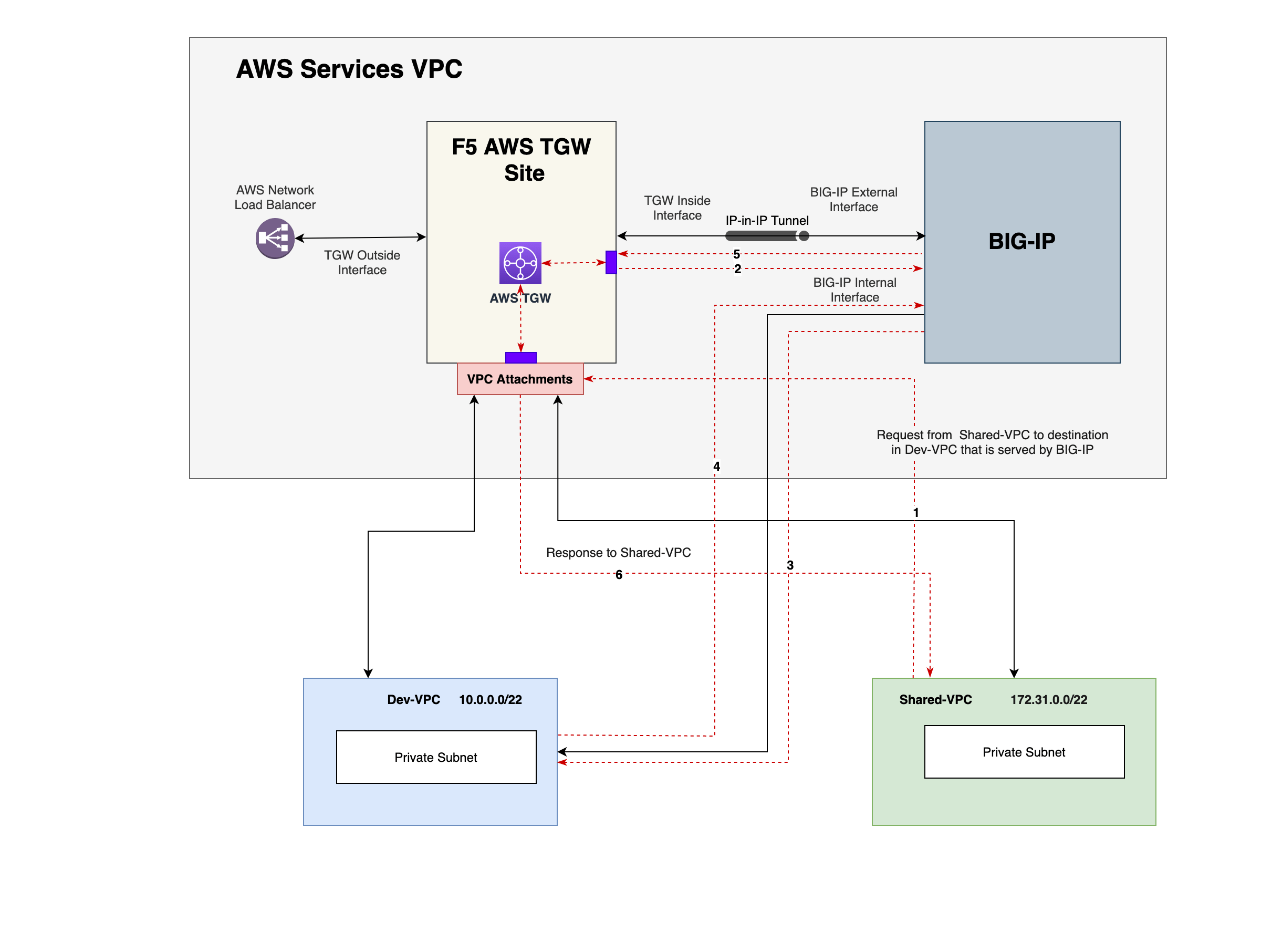
Figure: East-West Traffic in NFV Service Deployment
The following list presents the traffic flow for request and response:
-
Request from Shared-VPC to destination in Dev-VPC lands at AWS TGW.
-
TGW internally routes to the F5 AWS TGW Site's inside interface which in turn sends to BIG-IP external interface.
-
BIG-IP internally routes to inside interface and in turn sends the request to Dev-VPC.
-
Response from Dev-VPC to BIG-IP internal interface is in turn sent to external interface of BIG-IP.
-
Response then flows from BIG-IP external interface to TGW internal interface which in turn sends to Dev-VPC workload subnet attachment circuit.
-
TGW workload interface towards Shared-VPC sends the response to the requesting subnet in Shared-VPC to the requestor.
North-South Traffic
The AWS network load balancer receives the requests/traffic from internet and routes the traffic to the outside interface of the TGW Site. Based on the destination, the system checks the main route table and forwards the traffic to the inside interface of the Site. The traffic then is sent over an IP-in-IP tunnel between the Site inside interface and BIG-IP external interface. Using the services VPC route table, the next-hop is marked to the appropriate VPC attachment and propagated to the destination.
The response traffic forwarded to the BIG-IP instance internally using the spoke route table with the service VPC attachment as the destination. The BIG-IP then internally steers the traffic to its external interface and then sends over IP-in-IP tunnel to the Site's inside interface. The Site then performs SNAT based on the route table entries and sends the traffic to internet over the outside interface.
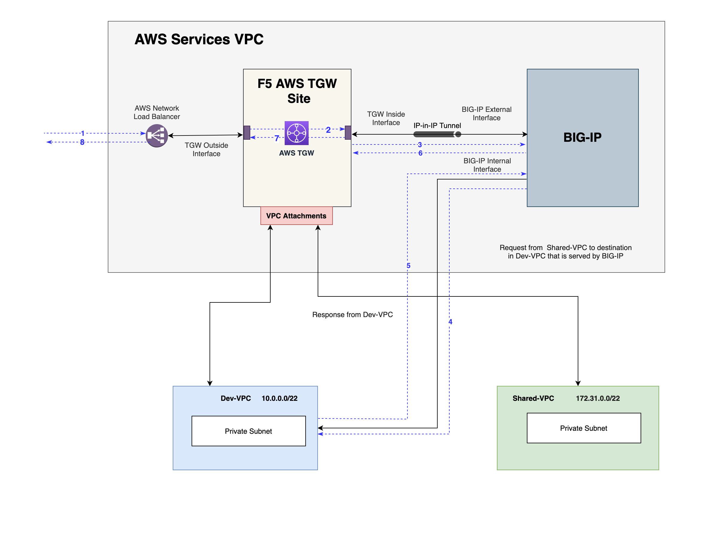
Figure: North-South Traffic in NFV Service Deployment
-
Request from Internet to destination in Dev-VPC lands at AWS Network Load Balancer which in turn routes it to the TGW.
-
TGW internally routes to the F5 AWS TGW Site's inside interface.
-
The request is then sent to BIG-IP external interface over IP-in-IP tunnel.
-
BIG-IP internally routes to inside interface and in turn sends the request to Dev-VPC.
-
Response from Dev-VPC is sent to BIG-IP internal interface which is internally routed to external interface of BIG-IP.
-
Response then flows from BIG-IP external interface to F5 AWS TGW Site's internal interface over IP-in-IP tunnel.
-
The response is then forwarded to the TGW which in turn sends it to the F5 AWS TGW Site's outside interface.
-
The F5 AWS TGW Site Outside interface sends the response to the AWS Network load balancer which in turn sends response to requestor over internet.
Note: For detailed information on BIG-IP configurations, see BIG-IP Documentation.
Prerequisites
The following prerequisites apply:
-
A Distributed Cloud Services Account. If you do not have an account, see Create an Account.
-
An Amazon Web Services (AWS) TGW Site. See AWS VPC Site Access Policies and AWS TGW Access Policies for required permissions.
-
A delegated domain. See Domain Delegation for more information.
-
F5 BIG-IP subscription.
Configuration
Deploying the NFV service requires first creating an NFV service object in the F5® Distributed Cloud Console, obtaining the management address of the NFV service instance from the Console, log into the NFV service instance, and configuring the origin servers where your application workloads are running.
Perform the instructions presented in the following chapters to deploy and manage the NFV service instances.
Create NFV Service Object
Log into the Console and do the following:
Step 1: Start creating NFV service object.
- On the Console home page, select the
Multi-Cloud Network Connectservice.
Note: Homepage is role based, and your homepage may look different due to your role customization. Select
All Servicesdrop-down menu to discover all options. Customize Settings:Administration>Personal Management>My Account>Edit work domain & skillsbutton >Advancedbox > checkWork Domainboxes >Save changesbutton.
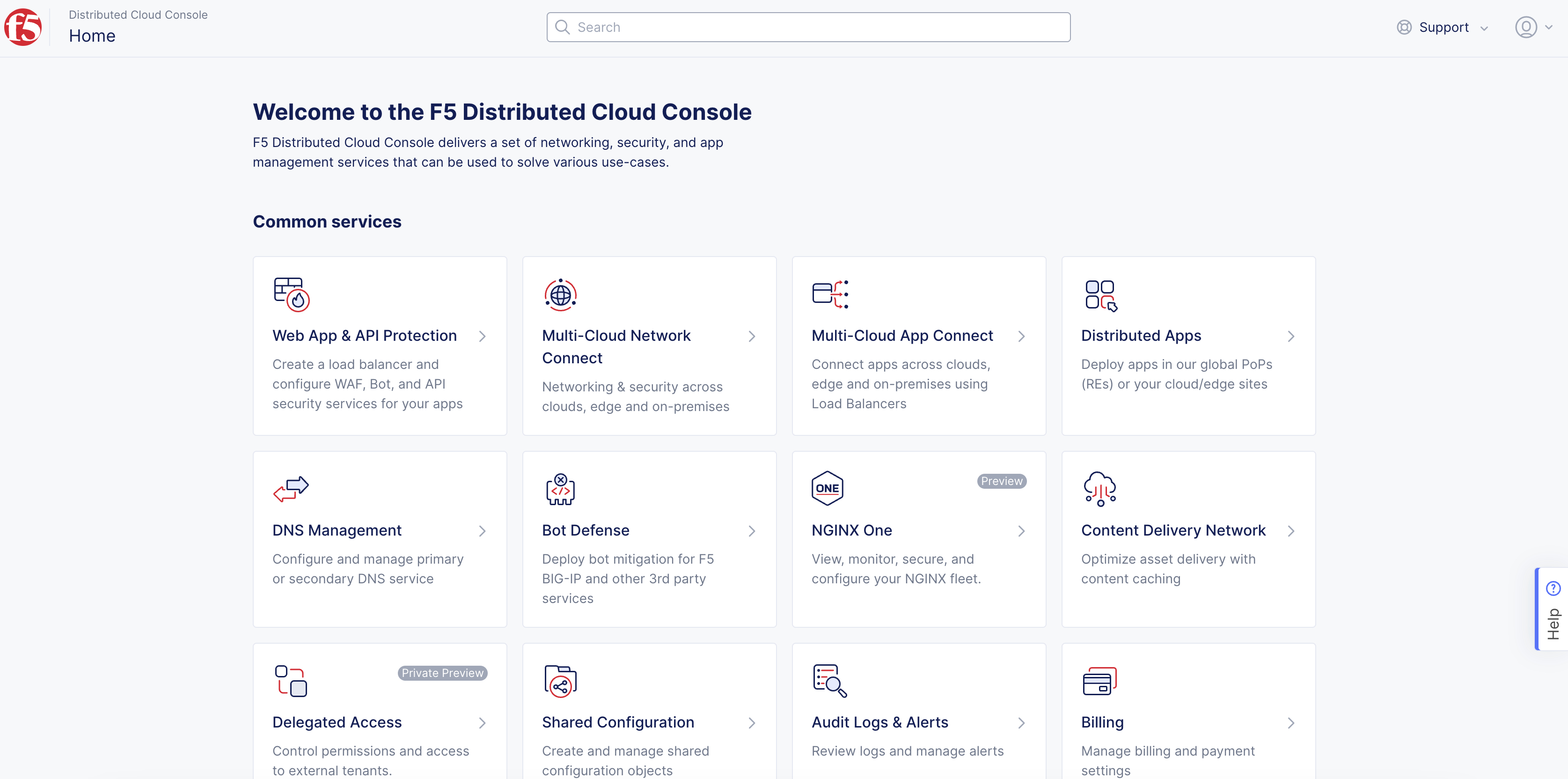
Figure: Console Homepage
-
Click
Manage>NFV Services. -
Click
Add NFV Serviceoption to open the NFV service object creation form. -
In the
Metadatasection, setName,Labels, andDescriptionas needed.
Step 2: Configure NFV service provider settings.
In the Spec section, perform the following:
-
Select
Virtual BIG-IP on AWSfor theExternal Service Providerfield. -
Click
Configureunder theVirtual BIG-IP on AWSfield. This opens the BIG-IP service specification form. -
From the
Imagemenu, selectBIG-IP Pay as You Go Image. This is populated by default. -
Select an option for the
AMI Choicefield. TheBIG-IP Advanced WAF (PAYG, 200Mbps)is selected by default. -
In the
Admin Usernamefield, enter an admin username that will be used with your BIG-IP account. -
Click
Configurein theAdmin Passwordsection. In the openedSecretpage, configure the settings for your password and then clickApply.
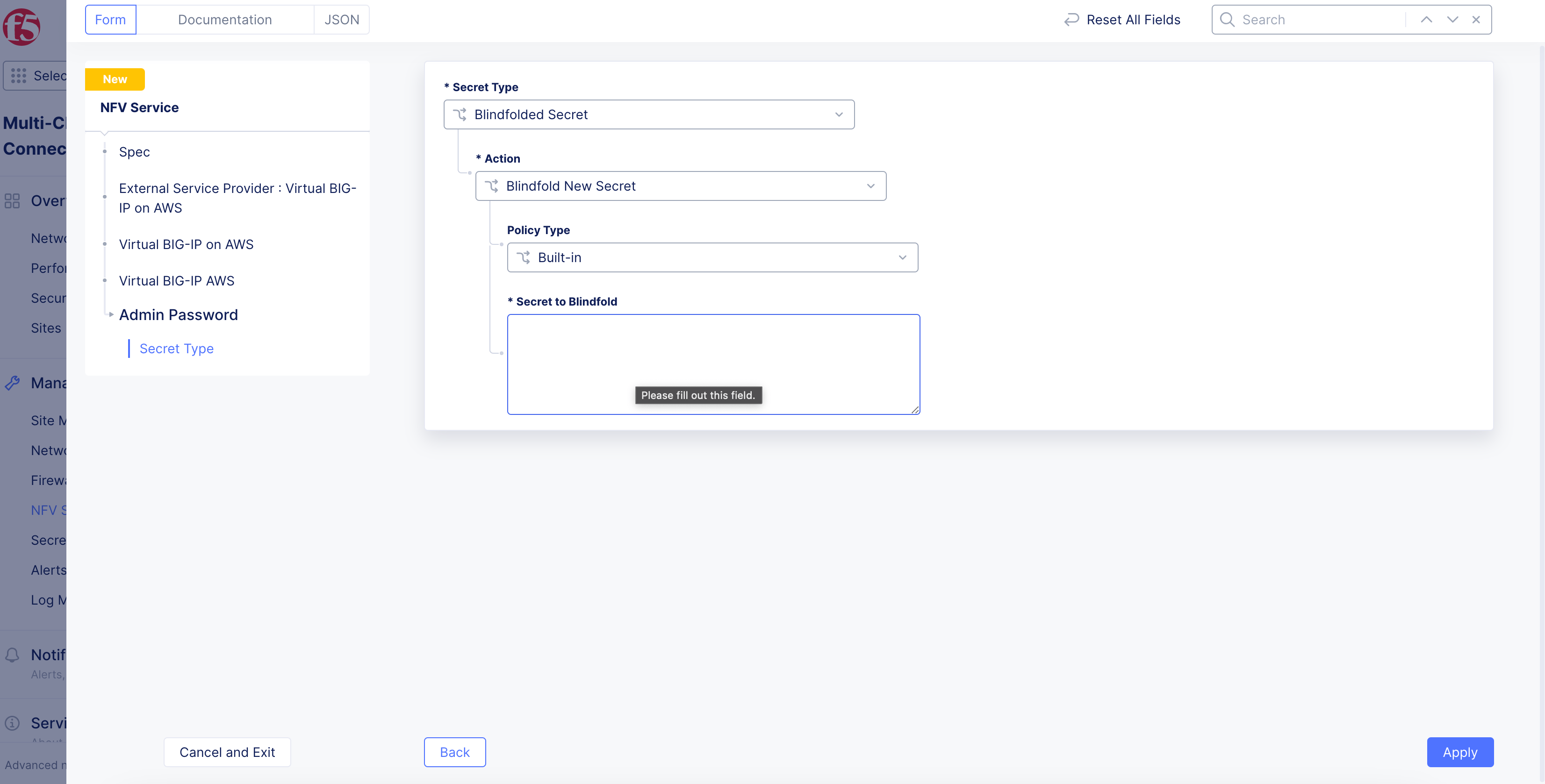
Figure: Encrypted Admin Password
- Enter your SSH key in the
Public SSH keysection.
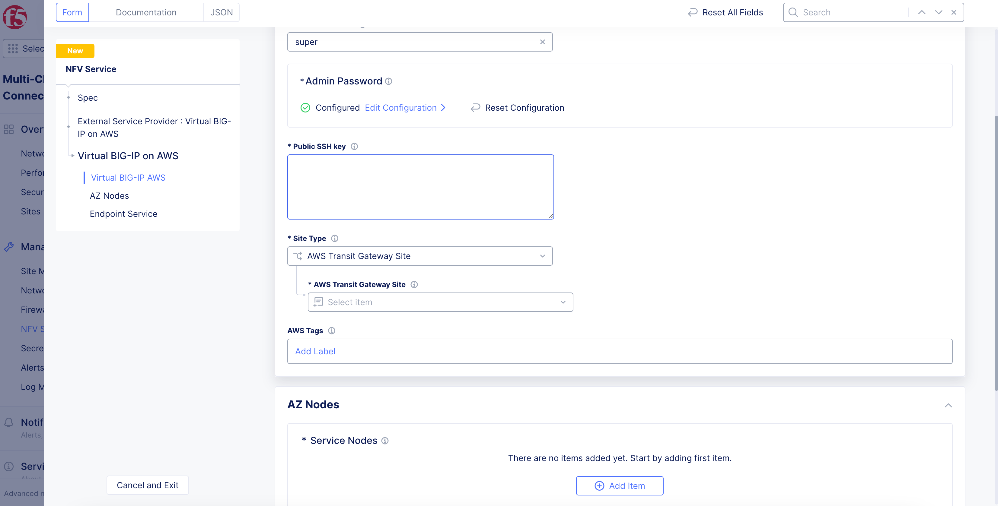
Figure: BIG-IP Service Configuration
-
Select
AWS Transit Gateway Sitefor theSite Typefield. Click on theAWS Transit Gateway Sitefield and select your AWS TGW site from the drop-down list. -
Click
Add Itemin theAZ Nodessection and do the following in the service nodes form:-
Enter a name in the
Node Namefield. This name will be used to form the hostname for the service. -
Click on
AWS AZ Namefield and select an AWS availability zone from the drop-down list. Ensure that you pick the same availability zone as that of the TGW Site. -
From the
Subnet for BIG-IP Management Interfacemenu, select an option to configure the management interface. -
Click
Applyto add the service node.
-
Note: Use the
Add Itemoption in theService Nodessection and repeat the above steps to add more service nodes.
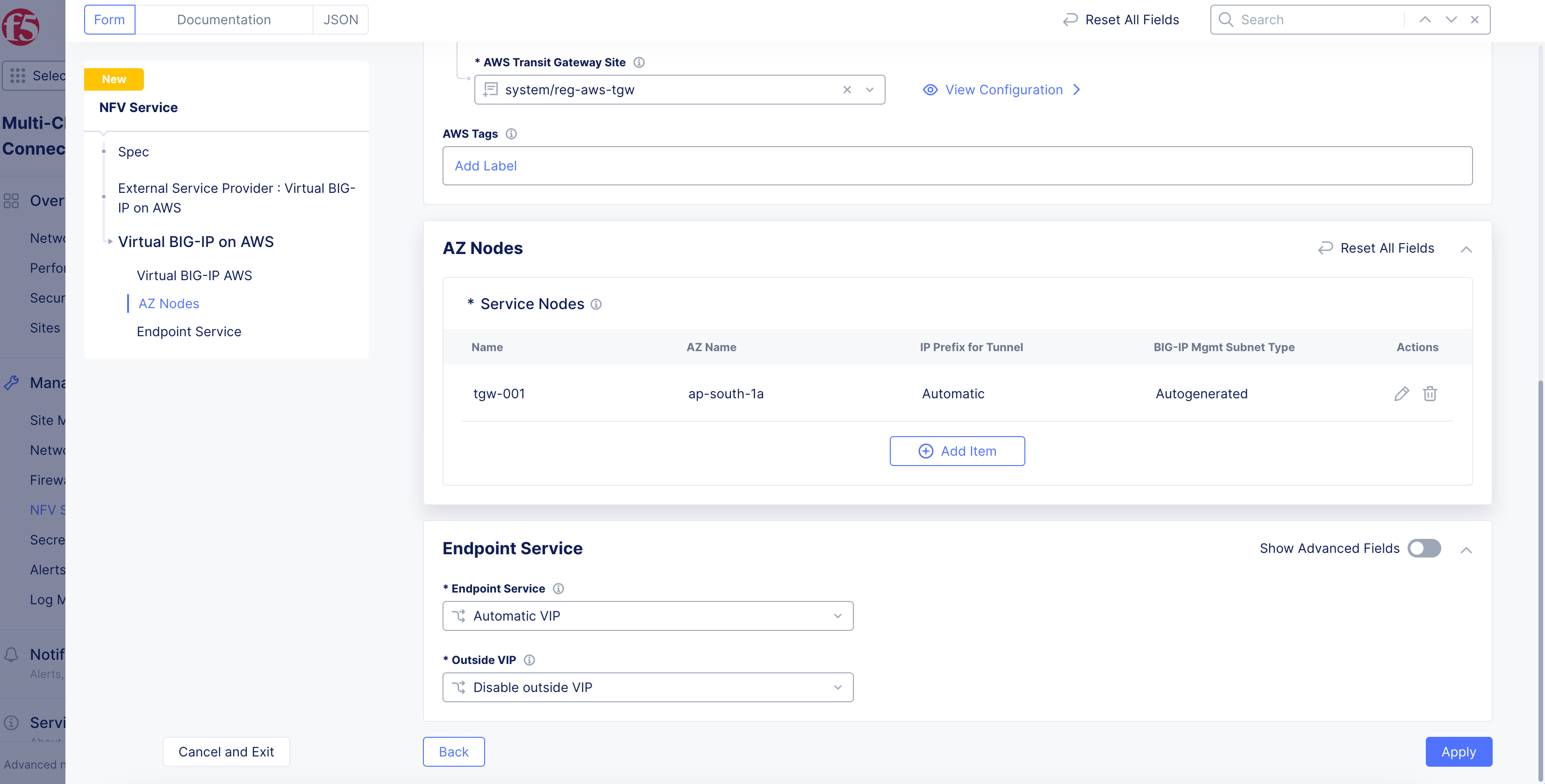
Figure: TGW and Service Nodes
Step 3: Configure external service VIP.
-
From the
Endpoint Servicemenu, set an option to advertise the VIP for East-West traffic. The default option allows the system to select a VIP. To add a custom VIP, selectConfigured VIPand then enter the IP address. -
Use the
Outside VIPmenu to set the configuration to advertise your load balancer on the site local network. The default option disables this function. You can select to advertise on the outside network or using cloud external IP address. -
Click
Apply.
Step 4: Optionally, set node management based on HTTP.
-
From the
HTTPS Based Management of Nodesmenu, enable theHTTPS Based Managementoption. -
Enter a domain suffix in the
HTTPS Based Managementfield. This will be used along with theNode Nameset in the previous step to form the management URL for the node.
Note: Ensure that the domain is delegated to F5 Distributed Cloud Services. Default HTTPS port is 443 and Internet access is enabled by default.
- From the
Access on Site Local Networksmenu, select an option for the site local network. The default option isEnable Internet Access. For all other options, clickConfigure. In the form that appears, configure TLS settings, and then clickApply.
Note: For enabling both the East-West and North-South traffic, configure both inside VIP and outside VIP. See the Design section to understand the traffic paths.
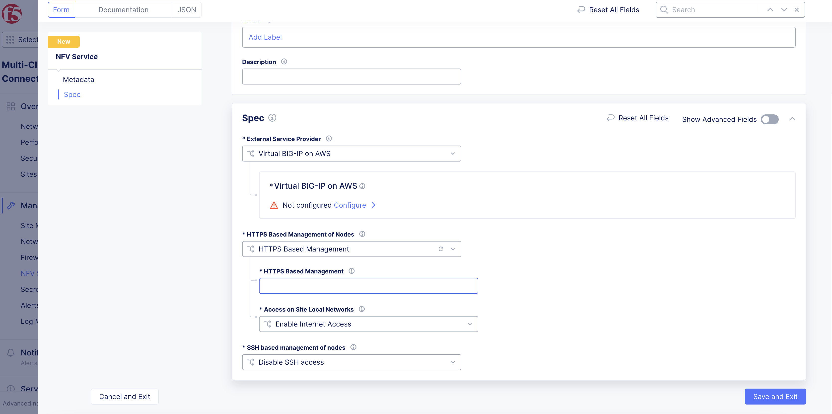
Figure: HTTP Based Node Management Settings
Step 5: Optionally, set node management based on SSH.
-
From the
SSH based management of nodesmenu, selectEnable SSH access to nodes. -
From the
Enable SSH access to nodesmenu, select an option for the site local network.
Note: It is recommended to use the default option of
Enable On Site Local Outside.
- Click
Add Item.
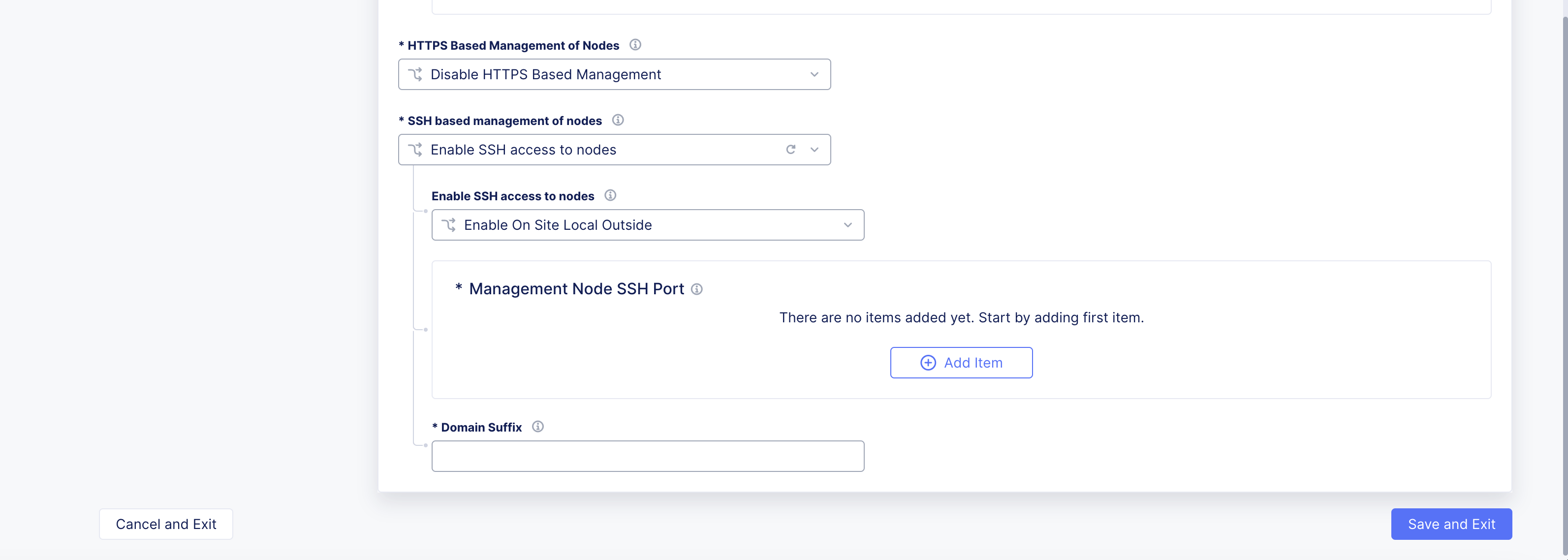
Figure: SSH Node Management
-
From the
Node Namemenu, select the node name to use for management. ClickSee Suggestionsto display a list. -
From the
SSH Portmenu, enter a TCP port number. -
Click
Apply. -
In the
Domain Suffixfield, enter a suffix value that will be used to generate the node hostname.
Step 6: Complete creating the NFV service object.
Click Save and Exit.
Step 7: Obtain management address for the service nodes.
-
Navigate to the NFV object created in the previous step under the
NFV Servicestab. TheDashboardpage is displayed. -
Under the
Service Instancessection, verify if the columns display the configuration previously set. TheManagement Dashboardcolumn shows the service node management URLs. It may take a few minutes for the items to appear.
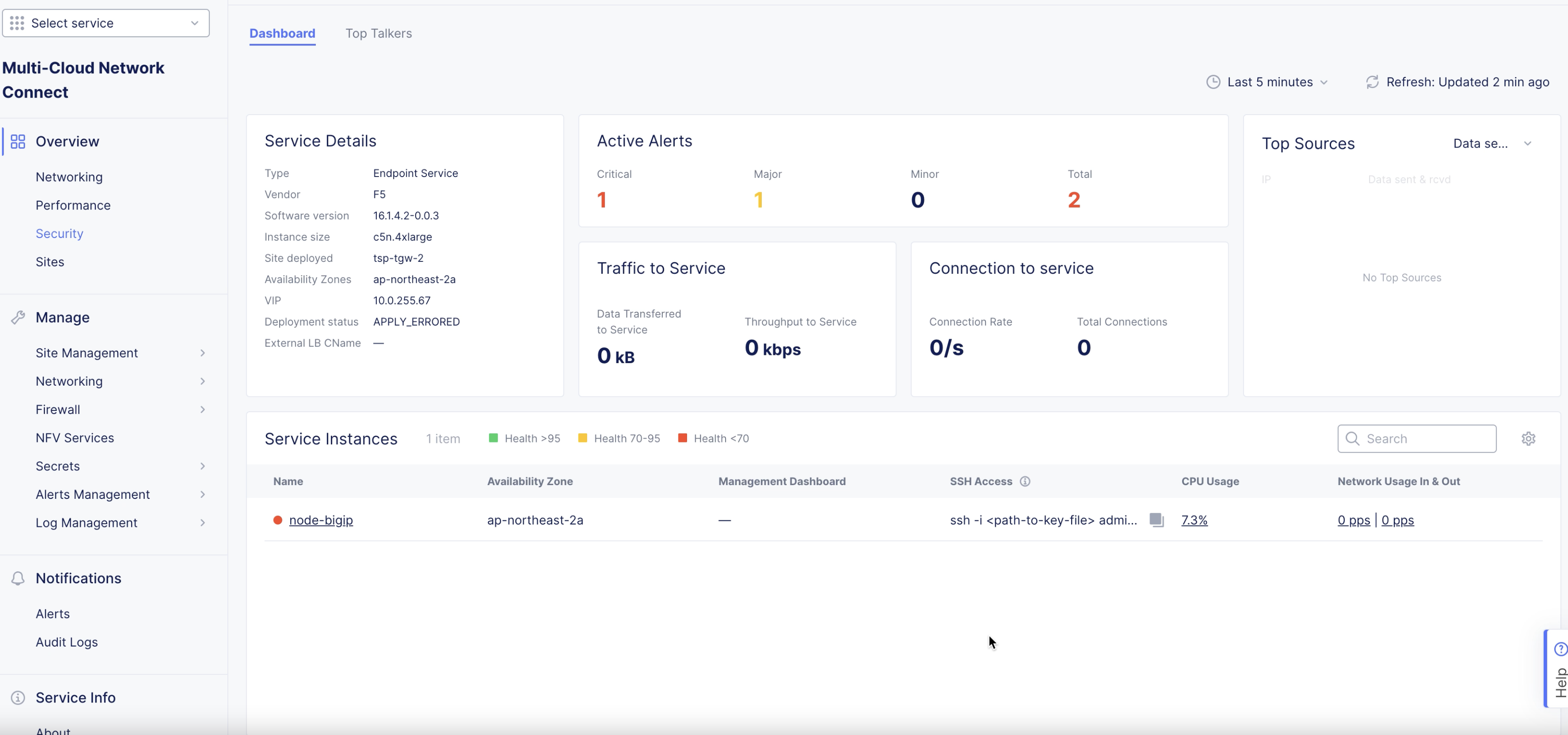
Figure: BIG-IP Management URL
Configure BIG-IP Instances
This chapter shows sample configuration for the BIG-IP service instance. For full instruction set, refer to BIG-IP documentation.
Step 1: Log into the BIG-IP service instance.
-
Open a browser window and enter the instance management URL obtained in the previous chapter.
-
Enter the admin username and password you configured in the previous chapter.
Step 2: Configure pool where the application workloads are running.
-
On the BIG-IP management portal, go to
Main>Local Trafficand clickPoolsunderVirtual Serverssection on the left menu. -
Click
Createon the pools list page to start creating a pool. -
Enter a name for your pool in the
Configurationsection. -
Enter an IP address for the
Addressfield in theResourcessection. -
Enter a port number in the
Service Portfield.
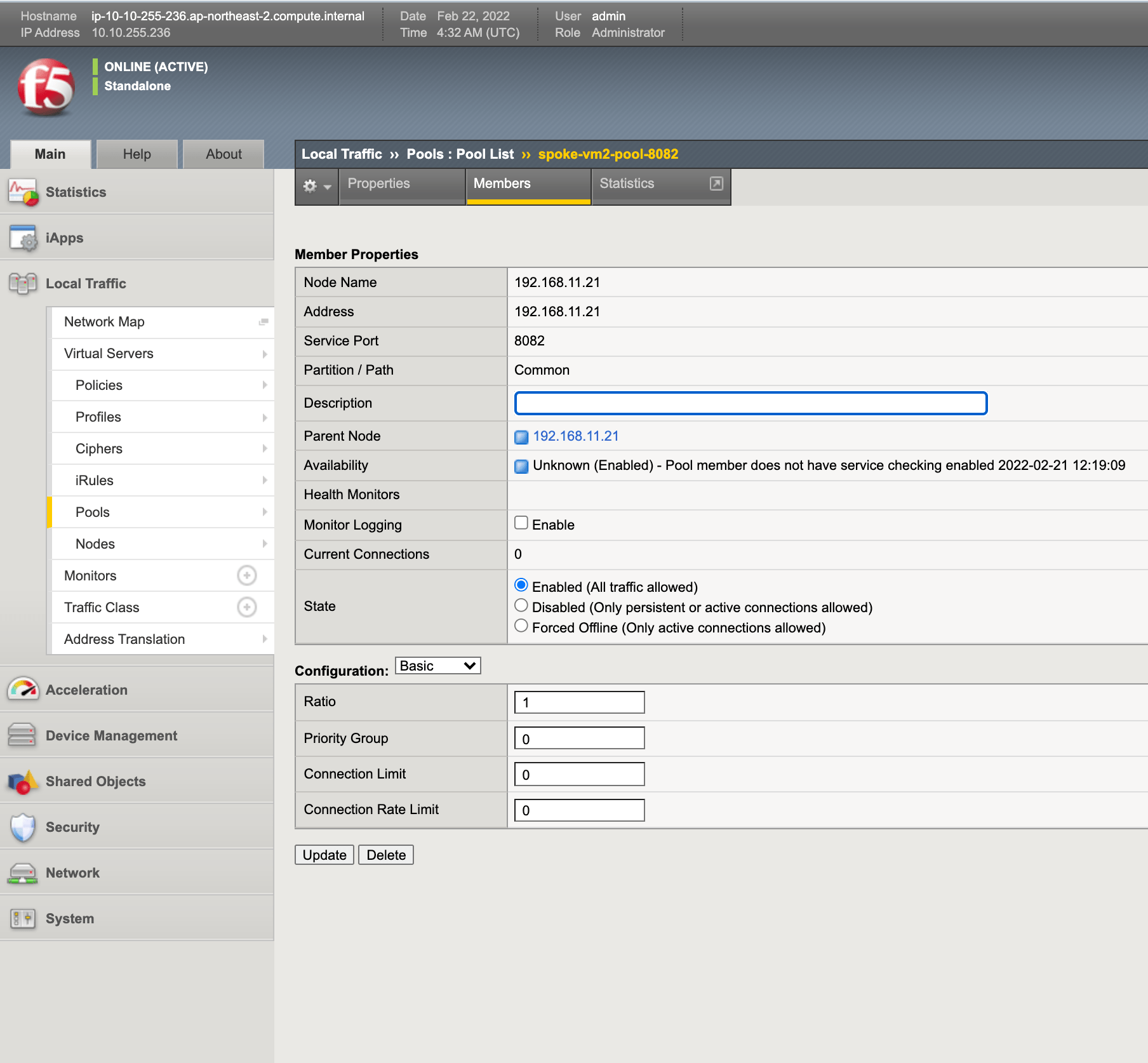
Figure: BIG-IP Pool Creation
- Click
Finishedat the bottom of the window to complete creating the pool.
Step 3: Configure virtual servers.
-
On the BIG-IP management portal, go to
Main>Local Trafficand clickVirtual Serverson the left menu. -
Click
Createon the virtual servers list page to start creating a virtual server. -
Do the following in the
General Propertiessection:-
Enter a name for your virtual server.
-
Select
Hostin theSource Addressfield and enter0.0.0.0/0. -
Select
Hostin theDestination Address/Maskfield and enter IP address for your host. -
Enter a port number in the
Service Portfield.
-
-
Select
Automapin theSource Address Translationfield. -
In the
Resourcessection, select the pools created in previous step.
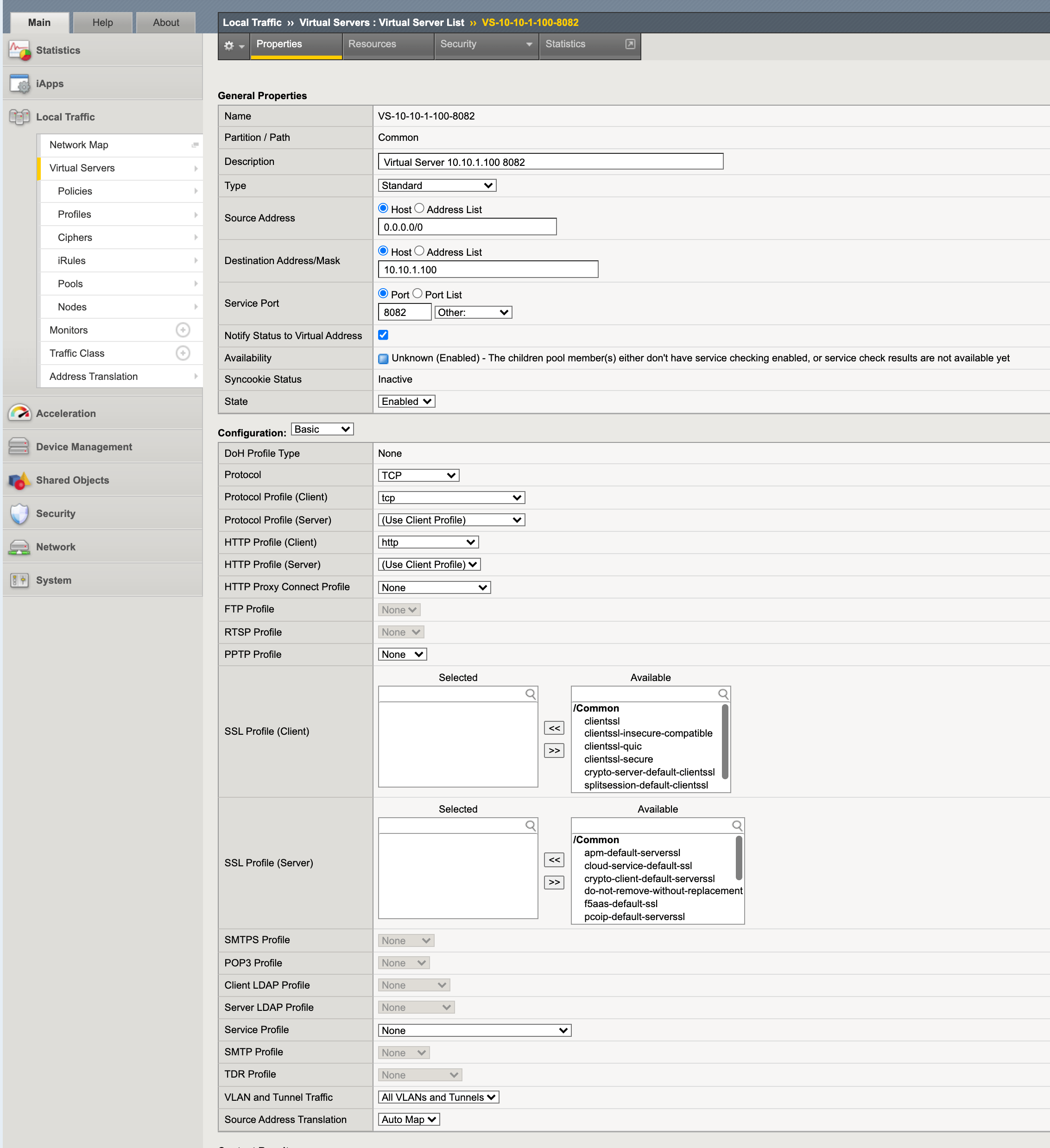
Figure: BIG-IP Virtual Server Creation
- Click
Finishedat the bottom of the window to complete creating the pool.
Verify Traffic
You can check the east-west TCP traffic flow by establishing an HTTP server on one VM on a subnet of any attached spoke VPC and an HTTP client from another VM of another spoke VPC. For example, you can run Apache HTTP server on spoke VPC 1 and send an HTTP request. Verify the traffic flow using tools such as tcpdump. Similarly, you can check UDP traffic by running UDP server on a spoke VPC and UDP client on another spoke VPC using tools, such as netcat.
You can also check the north-south traffic by sending request from a spoke VPC to any internet destination. You can check that SNAT happens from inside network to outside network on the AWS Site using the tools, such as traceroute.
This chapter shows how to monitor the NFV service using the Console.
Perform the following:
Step 1: Navigate to NFV services monitoring page.
-
Log into the Console and click on the
Multi-Cloud Network Connectservice. -
Select
Manage>NFV Serviceson the left menu. A list of NFV services objects is displayed on the right side. -
Click on your NFV services object from the list of displayed objects. Dashboard view is displayed by default. The dashboard shows snapshot information for entities such as service details, alerts, traffic, connections, top sources (IP addresses), and details about service instances.
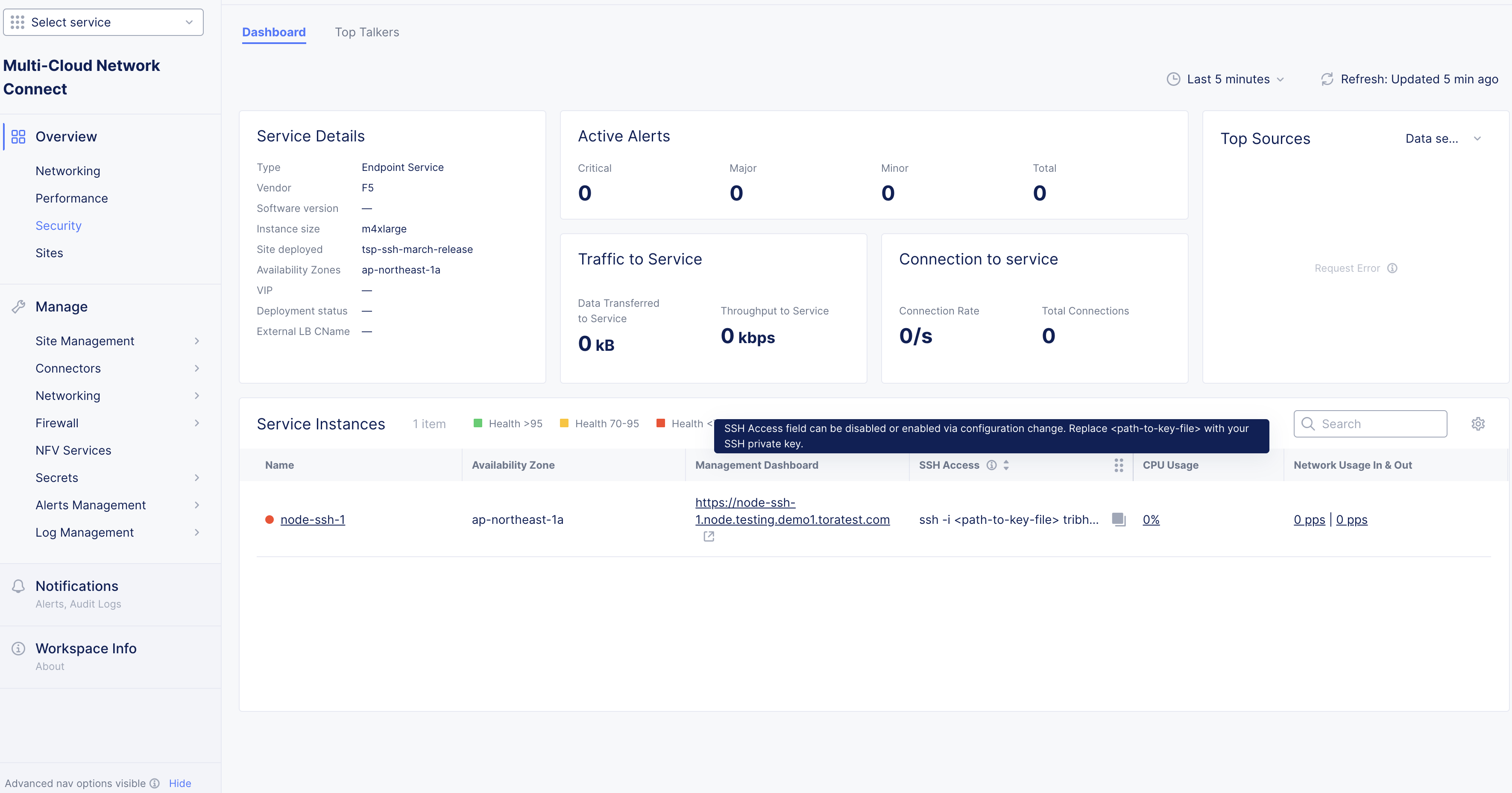
Figure: NFV Service Monitoring Dashboard View
Step 2: Inspect NFV service metrics and top talkers.
The metrics show historical information for CPU usage, throughput, and disk operation statistics.
-
From within the dashboard, click on the value on the
Node Namecolumn in theService Instancessection. TheMetricsview is displayed showing the CPU usage graph by default. -
Click on any metrics options located on the right side to display graphical view for that metric.
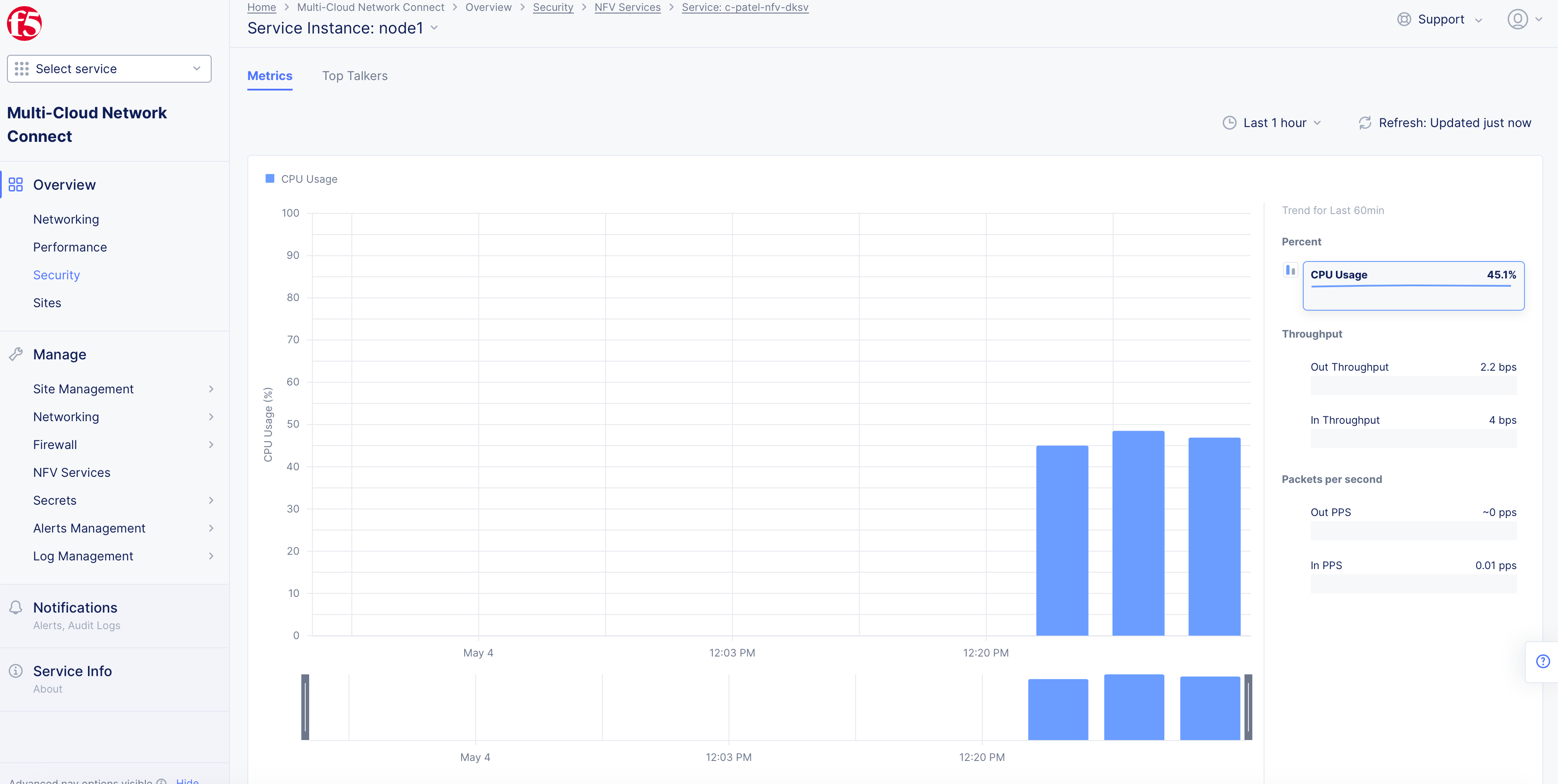
Figure: NFV Service Metrics View
- Click on the
Top Talkerstab to view the top 10 sources, destinations, applications, flows, and the associated data statistics.
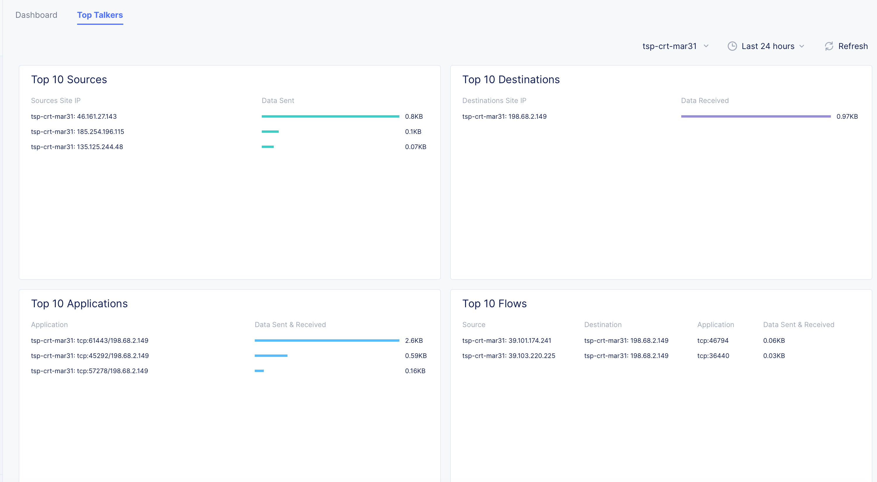
Figure: NFV Service Top Talkers View
Step 3: Navigate to site monitoring page.
-
Select
Multi-Cloud Network Connectservice. -
Go to
Overview>Sites. Click on your site from the list of displayed sites. This opens the site's dashboard.
Step 4: Inspect interfaces and requests for your site.
-
Click on the
Interfacestab to view the list of interfaces and associated metrics. -
Click on the
Connectionstab to view the list of connection requests and information for each request. -
Click on the
Top Talkerstab to view the list of top 10 sources, destinations, applications, flows, and the associated data statistics.
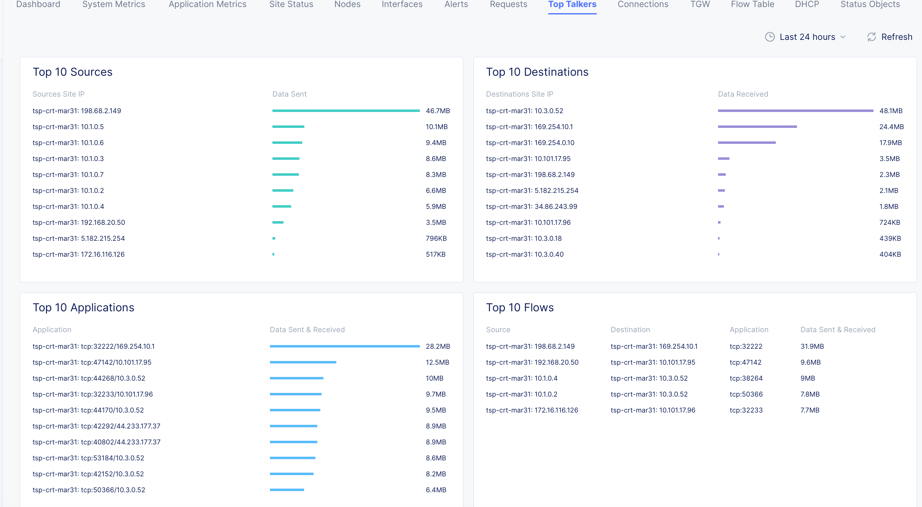
Figure: AWS TGW Site Top Talkers
- Click on the
Flow Tabletab to view the packet flow information.
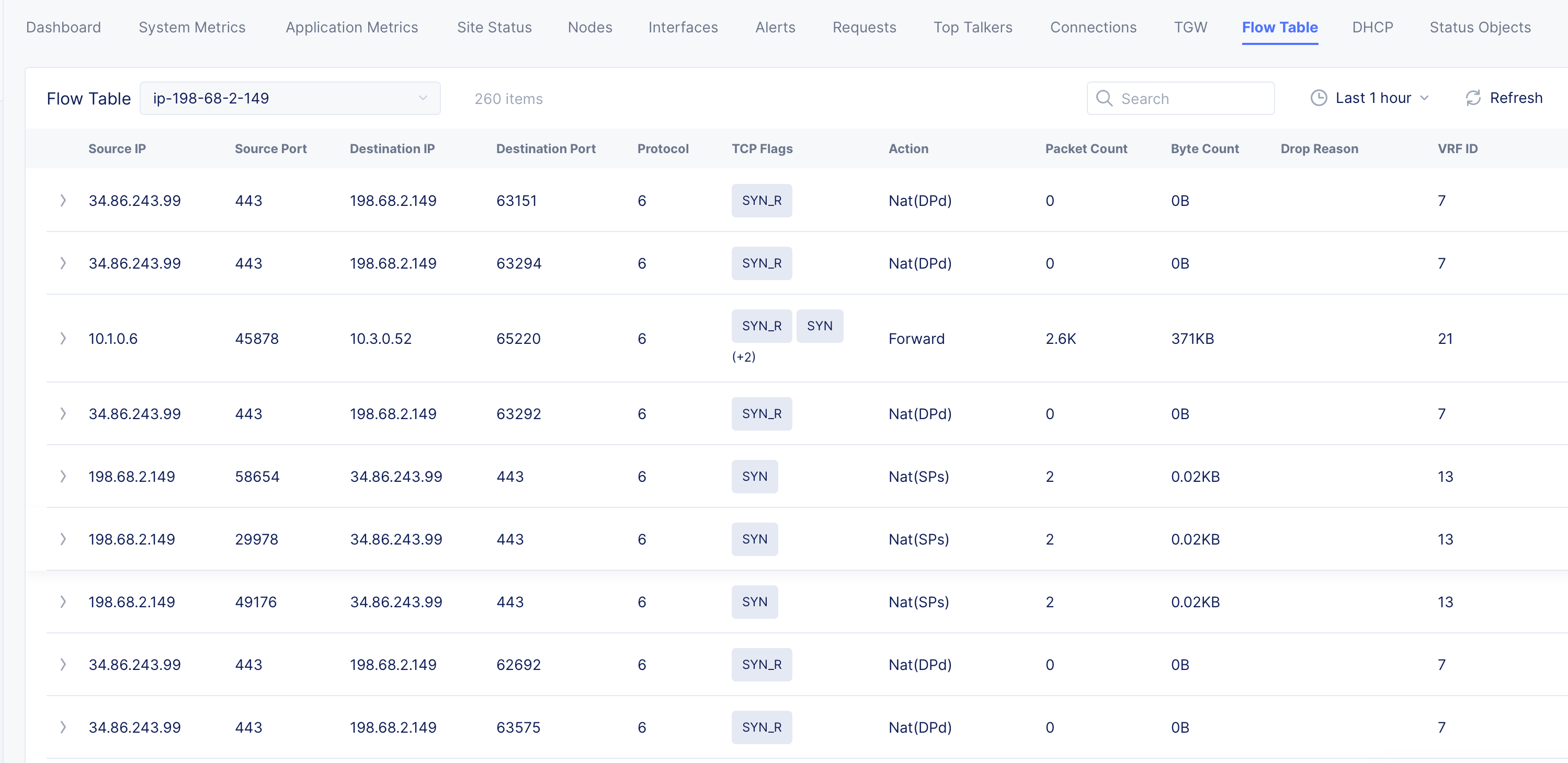
Figure: AWS TGW Site Flow Table Entries
Step 5: Inspect site connectivity map and route tables.
-
Go to
Sites>PoP (RE) Connectivity. -
Click on your Site from the list of displayed Sites or select your Site from the
Select sitedrop-down on the top. This opens the full connectivity map showing RE Sites, AWS Site, TGW, subnets, and the VMs in the attached VPCs.
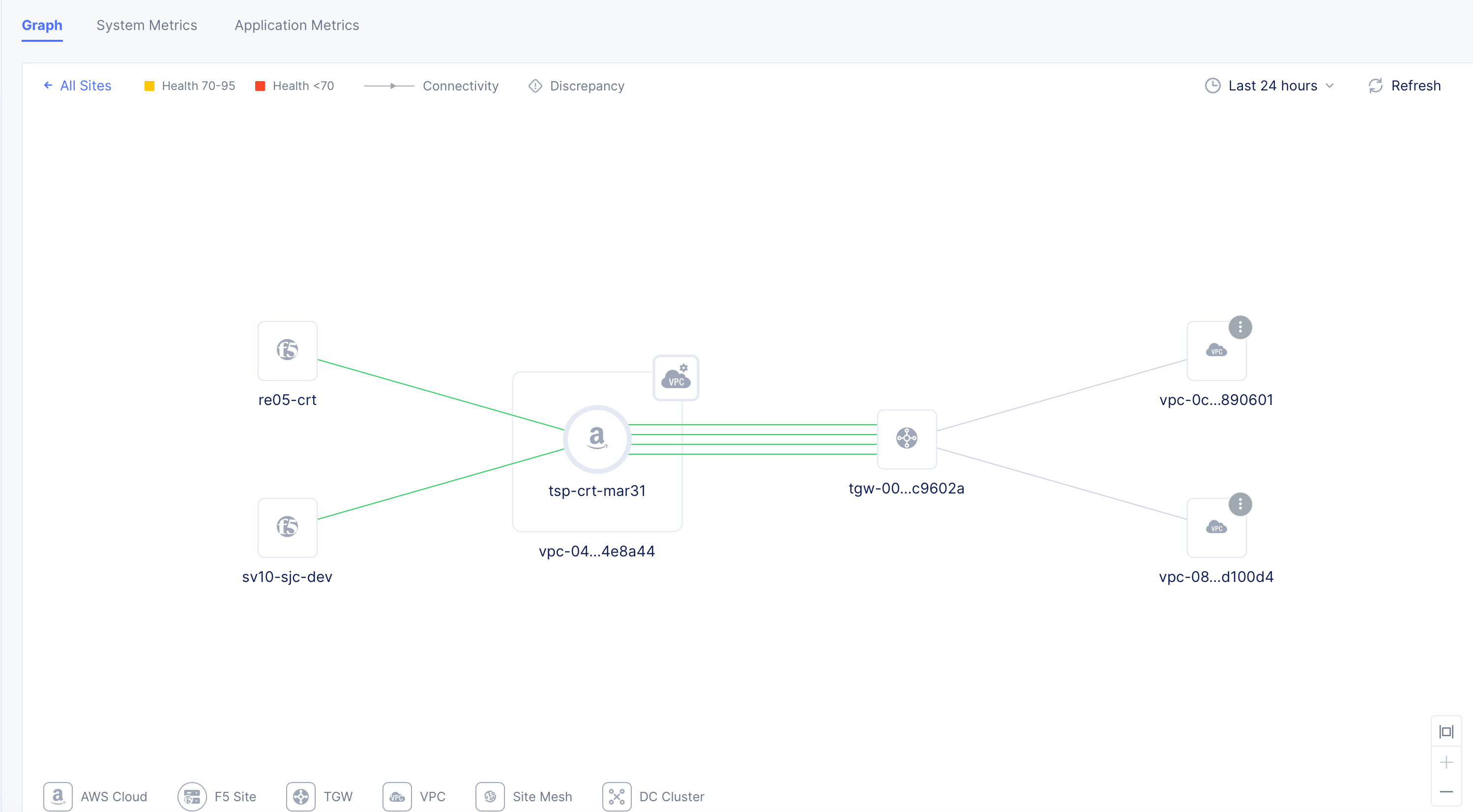
Figure: NFV Service Topology View
- Click on any VPC to load its connectivity map with Site or TGW and subnets. This also opens a modeless window with VPC information such as VM instances and route tables.
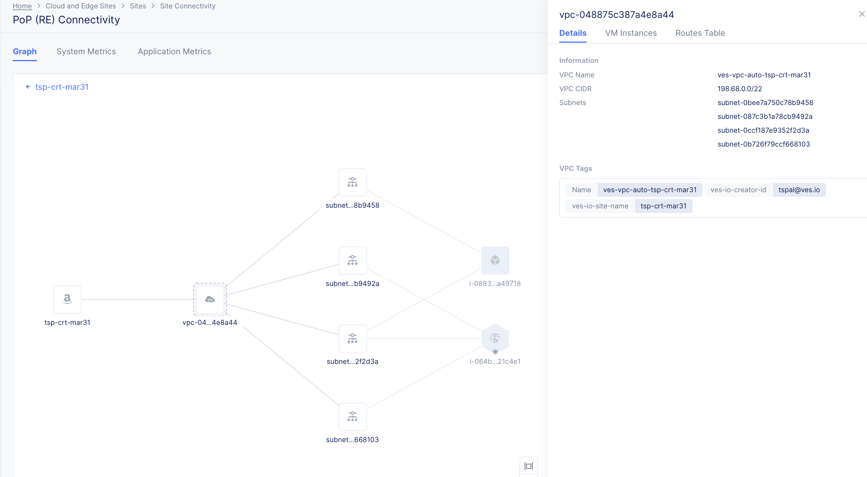
Figure: NFV Service VPC Topology View
- Click on any subnet or VM to view its information in the modeless window. In case of VMs, the view also displays network interface information.
Concepts
BIG-IP References
- Configuring a BIG-IP Virtual Server to Listen on a Port Range
- Configuring BIG-IP to Load Balance UDP Packets Individually