Create and Deploy Managed K8s
Objective
This document provides instructions on how to create a managed Kubernetes (K8s) cluster and deploy it on the F5® Distributed Cloud App Stack site. Managed K8s cluster is similar in principle to regular K8s, and you can use command-line interface (CLI) tools like kubectl to perform operations that are common to regular K8s. The F5 Distributed Cloud Platform provides a mechanism to easily deploy applications using managed K8s across App Stack sites that form DC clusters. To learn more about deploying an App Stack site, see Create App Stack Site.
Using the instructions provided in this guide, you can create a managed K8s cluster, associate it with an App Stack site, and deploy applications using its kubeconfig file.
Note: Managed K8s is also known as physical K8s.
Virtual K8s and Managed K8s
You can use both Distributed Cloud Virtual K8s (vK8s) and managed K8s for your applications. However, the major difference between Distributed Cloud vK8s and managed K8s is that you can create managed K8s only on Sites with App Stack functionality (in case of cloud Sites, the site type App Stack Cluster). The vK8s can be created in all types of Distributed Cloud sites, including Distributed Cloud Regional Edge (RE) sites. Also, you can deploy managed K8s across all namespaces of an App Stack site and manage the K8s operations using a single kubeconfig. The vK8s is created per namespace per site. While you can use vK8s and managed K8s in the same site, operations on the same namespace using both are not supported. See Restrictions for more information.
Reference Architecture
The image below shows reference architecture for the CI/CD jobs for app deployments to production and development environments. The production and development environments are established in different App Stack sites. Each site has CI/CD jobs and apps deployed in separate namespaces. The git-ops-prod and git-ops-dev namespaces have CI/CD jobs, such as ArgoCD, Concourse CI, Harbor, etc. These are integrated using the in-cluster service account. Services such as ArgoCD UI can be advertised on a site local network and users can access it for monitoring the CD dashboard.
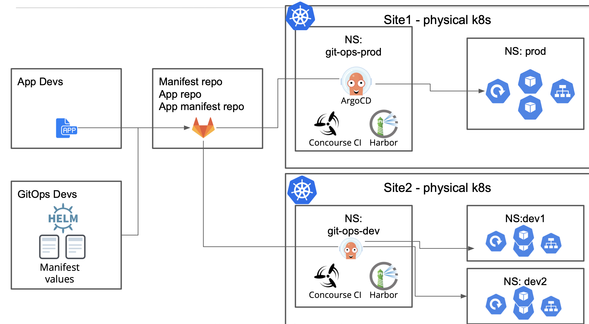
Figure: Reference Deployment Using Managed K8s
This image shows different types of service advertisements and communication paths for services deployed in different namespaces in the sites:
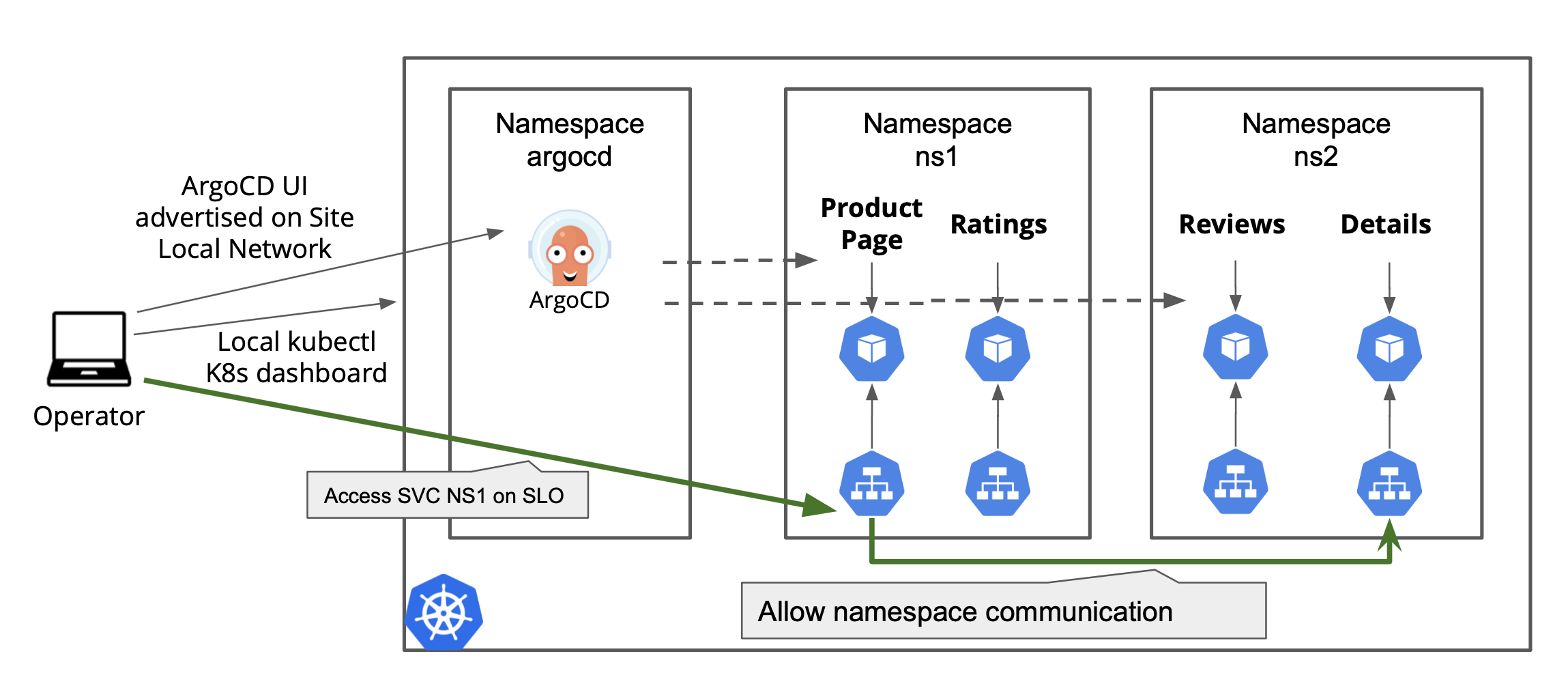
Figure: Intra-Namespace and Remote Communication for Managed K8s
Note: You can disable communication between services of different namespaces.
Prerequisites
-
An F5 Distributed Cloud Account. If you do not have an account, see Getting Started with Console.
-
A K8s application deployment manifest.
Restrictions
The following restrictions apply:
-
Using vK8s and managed K8s in the same site is supported. However, if the namespace is already used local to a managed K8s cluster, then any object creation in that namespace using vK8s is not supported for that site. Conversely, if a namespace is already used by vK8s, then operations on local managed K8s cluster are not supported.
-
Managed K8s is supported only for an App Stack site and not supported for other sites.
-
Managed K8s can be enabled by applying it before provisioning the App Stack site. It is not supported for enabling by updating an existing App Stack site.
-
Managed K8s cannot be disabled once it is enabled.
-
In case of managed K8s, Role and RoleBinding operations are supported via kubectl. However, ClusterRoleBinding, PodSecurityPolicy, and ClusterRole are not supported for kubectl. These can be configured only through F5 Distributed Cloud Console.
Note: As BGP advertisement for VIPs is included by default in Cloud Services-managed K8s, the
NodePortservice type is not required. Kubernetes service typeLoadBalancerandNodePortdo not advertise the service outside the K8s cluster. These function in the same way as theClusterIPservice type.
Configuration
Enabling a managed K8s cluster on an App Stack site requires you to first create it and apply it during App Stack site creation. You can also create a newly managed K8s cluster as part of the App Stack site creation process. This documentation shows creating a K8s cluster separately and attaches it to an App Stack site during creation.
Create Managed K8s Cluster
Perform the following steps to create a managed K8s cluster:
Step 1: Start K8s cluster object creation.
-
Log into Console.
-
Select the
Distributed Appsworkspace from the home page or theSelect workspacedrop-down menu. -
Select
Systemfrom theNamespacedrop-down menu at the top of the left navigation pane. -
Click
Manage>Manage K8s>K8s Clusters. -
Click
Add K8s Cluster.
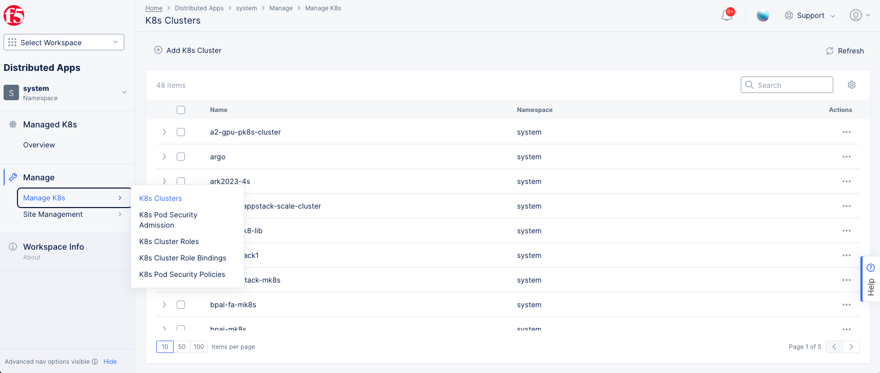
Figure: K8s Cluster Creation
Step 2: Configure metadata and access sections.
-
In the
Metadatasection, enter a name. -
Optionally, set labels and add a description.
-
In the
Accesssection, select theEnable Site Local API Accessoption from theSite Local Accessmenu. This enables local access to K8s cluster. -
In the
Local Domainfield, enter a local domain name for the K8s cluster in the<sitename>.<localdomain>format. The local K8s API server will become accessible via this domain name. -
From the
Port for K8s API Servermenu, selectCustom K8s Portand enter a port value in theCustom K8s Portfield. This example uses the default optionDefault k8s Port.
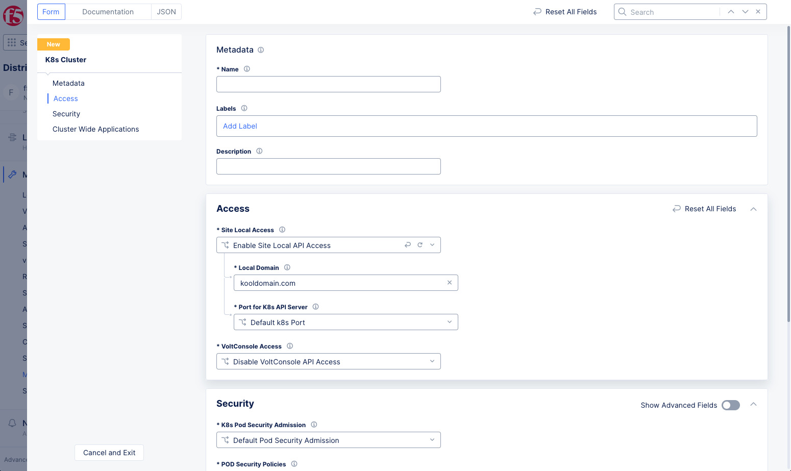
Figure: Access Section Configuration
- From the
VoltConsole Accessmenu, select theEnable VoltConsole API Accessoption.
Note: You can download the global kubeconfig for the managed K8s cluster only when you enable
VoltConsole API access. Also, if you do not enable the API access, monitoring of the cluster is done via metrics.
Step 3: Configure security settings.
The security configuration is enabled with default settings for pod security policies, K8s cluster roles, and K8s cluster role bindings. Optionally, you can enable custom settings for these fields.
Step 3.1: Configure custom pod security policies.
This step shows how to configure custom pod security admission. The procedure is different depending on your version of Kubernetes. Choose the appropriate set of steps:
Configure custom pod security policies for Kubernetes version 1.25 an up.
Note: Pod security admission is available from Kubernetes version 1.25 and above.The respective CE software version for enabling this feature is crt-20240326-2726.
-
In the
Securitysection, select theCustom Pod Security Admissionoption from theK8s Pod Security Admissionmenu. -
Use the
Pod Security Admission Listdrop-down menu to select a K8s pod security Admission from the list of displayed options or create a new pod security admission and attach. This example shows creating a new admission.
Create a new pod security admission per the following guidelines:
- Click in the
Pod Security Admission Listfield, and then click Add Item to open a new form.
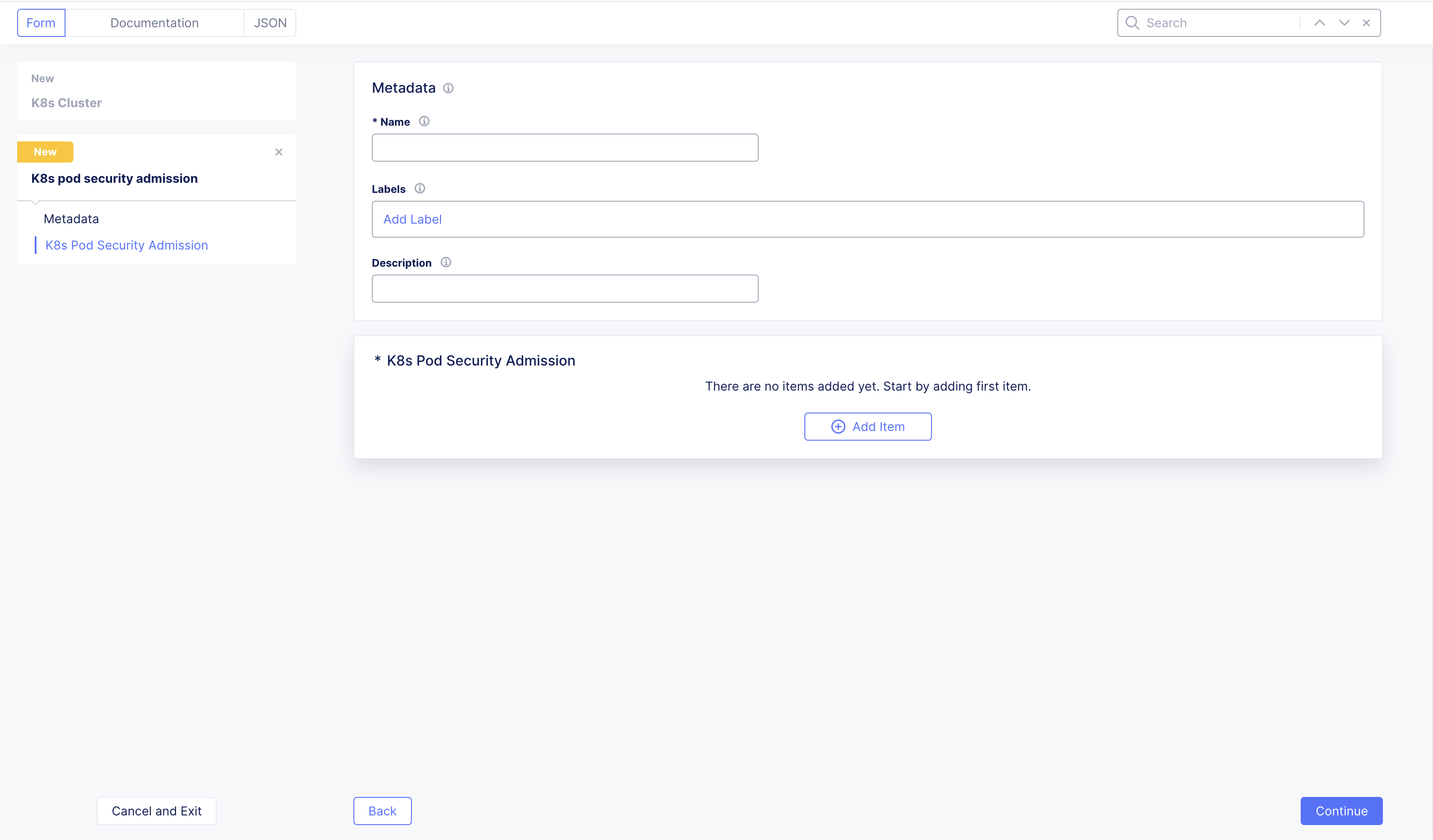
Figure: Pod Security Admission
-
In the
Metadatasection, enter a name. -
Optionally, set labels and add a description.
-
Under
K8s Pod Security Admissionfield, clickAdd Item. -
Select a
Policy Typeand anAdmission ModeunderPod Security Admission Specand apply. -
You can add more
Pod Security Admission Specby clickingAdd Item. -
Click
Applyto save the admission spec and then clickContinueto create and pod security admission to the K8s cluster.
Configure custom pod security policies for Kubernetes version 1.24 and below.
Deprecation Notice: Starting from Kubernetes version 1.25, pod security policies have been removed. Instead, please configure Pod Security Admission for Kubernetes version 1.25 and above. The Kubernetes version has been upgraded from 1.24 to 1.26 on CE software version crt-20240326-2726.
Step 3.1.1: Optionally, configure the volumes and mounts.
Configure the Volumes and Mounts section per the following guidelines:
- Click
Add itemunderVolume,Allowed Flex Volumes,Host Path Prefix, andAllowed Proc Mountsfields. Enter the values for those fields. You can add multiple entries using theAdd itemoption for each of these fields.
Note: Leaving an empty value for
Volumesdisables any volumes. For the rest of the fields, the default values are applied. In case ofHost Path Prefix, you can turn on theRead Onlyslider to mount a read-only volume.
- Enable the
Read Only Root Filesystemoption so that containers run with read-only root file system.
Step 3.1.2: Optionally, configure host access and sysctl.
Configure the Host Access and Sysctl section per the following guidelines:
-
Enable the
Host Network,Host IPC, andHost PIDoptions to allow the use of host network, host IPC, and host PID in the pod spec. -
Enter port ranges in the
Host Ports Rangesfield to expose those host ports.
Step 3.1.3: Optionally, configure security context.
Configure the Security Context section per the following guidelines:
-
From the
Select Runs As Usermenu, selectRun As User. -
From the
Select Runs As Groupmenu, selectRun As Group. -
From the
Select Supplemental Groupsmenu, selectSupplemental Groups Allowed. -
From the
Select FS Groupsmenu, selectFS Groups Allowed. -
For each of the fields above, enter the following configuration:
-
Click
Add itemand enter ID values in theStarting IDandEnding IDfields. You can add more ranges using theAdd itemoption. -
From the
Rulemenu, select theSee Common Valuesoption to expand the choices. -
Select one option only from
MustRunAs,MayRunAs, orRunAsAny.
-
-
Click
Apply. -
Click
Continueto create and apply the pod security policy to the K8s cluster.
Note: You can add more pod security policies using the
Add itemoption.
Step 3.2: Configure K8s cluster role.
-
From the
K8s Cluster Rolesmenu, select theCustom K8s Cluster Rolesoption. -
Click in the
Cluster Role Listfield and select a role from the displayed list or clickAdd Itemto create and attach it. This example shows creating a new cluster role.
Configure the cluster role object per the following guidelines:
-
In the
Metadatasection, enter a name. -
Optionally, set labels and add a description.
-
In the
Cluster Rolesection, selectPolicy Rule ListorAggregate Rulefrom theRule Typemenu.-
For the
Policy Rule Listoption, clickAdd Item. -
From the
Select Resourcemenu, selectList of ResourcesorList of Non Resource URL(s).-
For the
List of Resourcesoption, perform the following:-
In the
List of API Groupsfield, click in theEnter API Groupsmenu, and then clickSee Common Values. Select an option. You can add more than one list using theAdd itemoption. -
In the
Resource Typesfield, click in theEnter Resources Typesmenu, and then clickSee Common Values. Select an option. You can add more than one resource using theAdd itemoption. -
In the
Resource Instancesfield, clickAdd item. Enter a list of resource instances. You can add more than one resource using theAdd itemoption. -
In the
Allowed Verbsfield, click in theEnter Allowed Verbsmenu, and then clickSee Common Values. Select an option. You can add more than one entry using theAdd itemoption. Alternatively, you can enter the asterisk symbol (*) to allow all operations on the resources.
-
-
-
For
List of Non Resource URL(s)option, perform the following:-
Enter URLs that do not represent K8s resources in the
Non Resource URL(s)field. You can add more than one entry using theAdd itemoption. -
Enter allowed list of operations in the
Allowed Verbsfield. You can add more than one entry using theAdd itemoption. Alternatively, you can enter the asterisk symbol (*) to allow all operations on the resources. -
Click
Apply.
-
-
Note: You can add more than one list of resources in case of
Policy Rule Listoption.
-
For the
Aggregate Ruleoption, click on theSelector Expressionfield and set the label expression by performing the following:-
Select a key or type a custom key by clicking
Add label. -
Select an operator and select a value or type a custom value.
-
Note: You can add more than one label expressions for the aggregate rule. This will aggregate all rules in the roles selected by the label expression.
- Click
Continueto create and assign the K8s cluster role.
Note: You can add more cluster roles using the
Add itemoption.
Step 3.3: Configure K8s cluster role bindings.
-
From the
K8s Cluster Role Bindingsmenu, select theCustom K8s Cluster Role Bindingsoption. -
Click on the
Cluster Role Bindings Listfield and then select a role binding from the displayed list, or clickAdd itemto create and attach it. This example shows creating a new cluster role binding.
Configure the cluster role binding per the following guidelines:
-
Enter a name in the
Metadatasection. -
From the
K8s Cluster Rolemenu, select the role you created in the previous step. -
In the
Subjectssection, select one of the following options in theSelect Subjectfield:-
Click
Add item. -
Select
Userand then enter a user in theUserfield. -
Select
Service Accountand then enter a namespace and service account name in theNamespaceandNamefields, respectively. -
Select
Groupand enter a group in theGroupfield. -
Click
Apply.
-
-
Click
Continueto create and assign the K8s cluster role binding.
Note: You can add more cluster role bindings using the
Add itemoption.
Step 3.4: Advanced K8s cluster security settings.
-
Enable the
Show Advanced Fieldstoggle to see the options necessary for this section. -
If you have Docker insecure registries for this cluster, select
Docker insecure registriesfrom theDocker insecure registriesmenu, and enter the insecure registry into the list. UseAdd itemto add more insecure registries. -
If you want to allow Cluster Scoped Roles, RoleBindings, MutatingWebhookConfiguration, and ValidatingWebhookConfiguration Access, select the
Allow K8s API Access to ClusterRoles, ClusterRoleBindings, MutatingWebhookConfiguration and ValidatingWebhookConfigurationoption.
Note: Once webhooks are allowed, you can use
kubectlagainst any managed k8s global kubeconfig to set up the webhook.For example, to create a webhook:
$ kubectl --kubeconfig kubeconfig_global.yml create -f https://raw.githubusercontent.com/chaos-mesh/chaos-mesh/master/config/webhook/manifests.yamlAnd to delete the webhook:
$ kubectl --kubeconfig kubeconfig_global.yml delete -f https://raw.githubusercontent.com/chaos-mesh/chaos-mesh/master/config/webhook/manifests.yaml
Step 4: Configure cluster-wide applications.
The default option is set to No Cluster Wide Applications.
-
To configure this option, select
Add Cluster Wide Applicationsfrom theK8s Cluster Wide Applicationsmenu. -
Click
Configure. -
Click
Add Item. -
From the
Select Cluster Wide Application, select an option. -
If you select
Argo CD, clickConfigureand complete the settings and clickApply. -
After you finish, click
Add Item. -
Click
Apply.
Step 5: Complete creating the K8s cluster.
Click Save and Exit to complete creating the K8s cluster object.
Attach K8s Cluster to App Stack Site
Perform the following steps to attach a K8s cluster:
Note: This example does not show all the steps required for App Stack site creation. For complete instructions, see Create App Stack Site.
Step 1: Start creating the App Stack site.
-
Log into Console.
-
Select the
Distributed Appsworkspace from the home page or theSelect workspacedrop-down menu. -
Click
Manage>Site Management>App Stack Sites. -
Click
Add App Stack Site.
Step 2: Attach the K8s cluster.
-
In the
Advanced Configurationsection, enable theShow Advanced Fieldsoption. -
From the
Site Local K8s API accessmenu, selectEnable Site Local K8s API access. -
Click on the
Enable Site Local K8s API accessfield and select the K8s cluster created in the previous section.
Step 3: Complete creating App Stack site.
-
Install nodes and complete registration for the App Stack site. For more information, see Perform Registration chapter of the Create App Stack Site document.
-
Click
Save and Exitto complete creating the App Stack site.
Step 4: Download the kubeconfig file for the K8s cluster.
-
Navigate to
Managed K8s>Overview. -
Click
...for your App Stack site enabled with managed K8s and perform one of the following:-
Select
Download Local Kubeconfigfor managing your cluster locally, when the cluster is on an isolated network. -
Select
Download Global Kubeconfigfor managing your cluster remotely from anywhere.
-
Note: The
Download Global Kubeconfigoption is enabled only when you enable Console API access.
- Save the kubeconfig file to your local machine.
You can use this kubeconfig file for performing operations on local K8s. This is similar to the regular K8s operations using tools like kubectl.
Note: You may have to manage name resolution for your domain for K8s API access. Local kubeconfig will expire in 15 days regardless of your credential expiration policy. You will need to get a new kubeconfig after that.
Step 5: Deploy applications to the managed K8s cluster.
Prepare a deployment manifest for your application and deploy using the kubeconfig file downloaded in the previous step.
- Type
kubectl apply -f k8s-app-manifest.yaml --kubeconfig k8s-kubecfg.yaml.
kubectl apply -f k8s-app-manifest.yaml --kubeconfig k8s-kubecfg.yaml
- To verify deployment status, type
kubectl get pods --kubeconfig k8s-kubecfg.yaml.
kubectl get pods --kubeconfig k8s-kubecfg.yaml
Note: In case you are using the local kubeconfig to manage the cluster, ensure that you resolve the domain name of the cluster to the IP address of the cluster. You can obtain the domain name from the kubeconfig file.
Manage PK8s with VMs
Managed k8s (or physical k8s or pk8s) can be provisioned with the ability to run VMs in Kubernetes. App Stack sites also support virtual machines (VMs).
KubeVirt allows your virtual machine workloads to run as pods inside a Kubernetes cluster. This allows you to manage them with Kubernetes without having to convert them to containers.
Note: You can also configure multiple interfaces for Virtual Machines (VM) or containers running in a K8s cluster within an App Stack Site. For instructions, see Create Workloads with Multiple Network Interfaces.
Step 1: Download Kubeconfig file for your pk8s.
-
Log into Console.
-
Select the
Distributed Appsworkspace from the home page or theSelect workspacedrop-down menu. -
Click
Managed K8s>Overviewand find your K8s cluster. -
Click
...under theActionscolumn for your cluster to download its kubeconfig. You can download the local or global kubeconfig file.
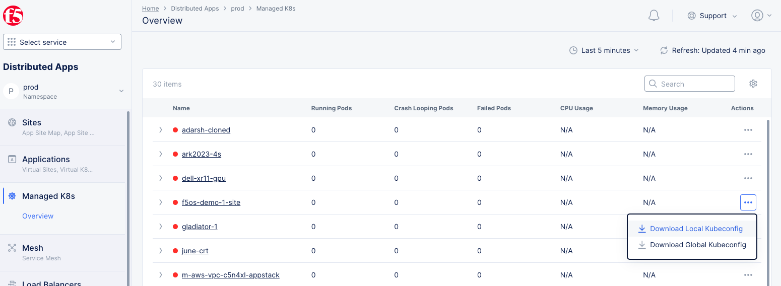
Figure: Download PK8s Kubeconfig
Step 2: Create a YAML manifest for your VM configuration.
Below is a sample VM configuration. For this example, the YAML manifest is named vm-sample.yaml.
apiVersion: kubevirt.io/v1
kind: VirtualMachine
metadata:
  name: testvm
spec:
  running: true
  template:
    metadata:
      labels:
        kubevirt.io/size: small
        kubevirt.io/domain: testvm
    spec:
      domain:
        devices:
          disks:
            - name: containerdisk
              disk:
                bus: virtio
            - name: cloudinitdisk
              disk:
                bus: virtio
          interfaces:
          - name: default
            masquerade: {}
        resources:
          requests:
            memory: 64M
      networks:
      - name: default
        pod: {}
      volumes:
        - name: containerdisk
          containerDisk:
            image: quay.io/kubevirt/cirros-container-disk-demo
        - name: cloudinitdisk
          cloudInitNoCloud:
            userDataBase64: SGkuXG4=
Step 3: Create the VM using kubectl.
-
Switch to a command line-interface (CLI).
-
Create the VM using the following command:
kubectl apply -f vm-sample.yaml --kubeconfig ves_system_pk8s4422_kubeconfig_global.yaml`
Note: This example uses the
--kubeconfigoption to be more explicit. You can leave this option out if you 1) name your kubeconfig fileconfigand place it in your$HOMT/.kubedirectory, or 2) use theKUBECONFIGenvironment variable.
Step 4: Interact with the VM on the CLI.
Once the VM is applied to the K8s Cluster, you can interact with it using an F5 Distributed Cloud CLI tool called virtctl. You can use virtctl to control the VM with a number of commands:
-
start -
stop -
pause -
restart -
console -
To get
virtctl, download the binary using one of the following commands (get thedarwinversion for macOS or thelinuxversion for a Linux system):
curl -LO "https://downloads.volterra.io/releases/virtctl/$(curl -s https://downloads.volterra.io/releases/virtctl/latest.txt)/virtctl.darwin-amd64"
curl -LO "https://downloads.volterra.io/releases/virtctl/$(curl -s https://downloads.volterra.io/releases/virtctl/latest.txt)/virtctl.linux-amd64"
- Make the binary executable.
chmod +x virtctl.darwin-amd64
- Interact with your VM with commands, such as the following:
./virtctl.darwin-amd64 pause <vm-name> --kubeconfig <path-to-kubeconfig>
Note: You can run
virtctlwith no parameters to see the full list of available commands. Console also provides some controls for your VM. See Monitor your Managed K8s.
Step 5: Delete your VM.
You can delete (destroy) the VM using the following command:
kubectl delete -f vm-sample.yaml --kubeconfig ves_system_pk8s4422_kubeconfig_global.yaml`
Export VMs on PK8s
Step 1: Create a PersistentVolumeClaim (PVC) to be used by the machine.
Use kubectl to create the PVC, as follows:
kubectl apply -f <manifest.yaml> --kubeconfig <kubeconfig of Pk8s>
The manifest.yml file is shown below:
apiVersion: v1
kind: PersistentVolumeClaim
metadata:
  name: fedora-data
  namespace: default
spec:
  accessModes:
  resources:
    requests:
      storage: 8Gi
Step 2: Create a VM.
Use kubectl to create the VM:
kubectl apply -f <manifest.yaml> --kubeconfig <kubeconfig of Pk8s>
manifest.yml file:
apiVersion: kubevirt.io/v1
kind: VirtualMachine
metadata:
  name: fedora
  namespace: default
spec:
  running: true
  template:
    spec:
      domain:
        resources:
          requests:
            memory: 1024M
        devices:
          disks:
          - name: containerdisk
            disk:
              bus: virtio
          - name: cloudinitdisk
            disk:
              bus: virtio
          - name: emptydisk
            disk:
              bus: virtio
          - name: data
            disk:
              bus: virtio
      volumes:
      - name: data
        persistentVolumeClaim:
          claimName: fedora-data
      - name: emptydisk
        emptyDisk:
          capacity: "2Gi"
      - name: containerdisk
        containerDisk:
          image: kubevirt/fedora-cloud-container-disk-demo:latest
      - name: cloudinitdisk
        cloudInitNoCloud:
          userData: |-
            #cloud-config
            password: fedora
            ssh_authorized_keys:
            - ssh-rsa AAAAB3NzaC1yc2EAAAADAQABAAABAQDyqbOXVV1s1eLCeasY9rl05uo+aCy0mgIZMff1o53UB8y5wniCJ+angW0soMBu0V51iNwn1wlgnC5LGfIetdcpGNrBHx9z4Mbiyq9uuh+tgfKS+hT4UMXc5l8tdlxbMoOtwe4MgtKA1/iFN6bLW+6xeVniqpppscOpug0zuChEtmy24xUCZzWPDKl56U5z6kP4HNLyq942DukqDo6csjR2qEagqqTrQoGNRuabKqhhKq/o4CX8ql37CwgR7EZpjS9iEmRPdNQ70FYoxYcW6EB+iYAUjnaOhUHytsImT9J7jNJDytzcqQlhyS/h/iIvVnh73trX3Od10WKIKhkhrCOD root@prague-karlin-01
Step 3: Attach the volume (referenced by PVC).
Attach the volume referenced by PVC
Step 4: Write some data to the volume (content for the snapshot of the VM).
Add data so that the snapshot contains data when exported.
Step 5: Stop the VM.
Use virtctl stop or the stop option of managed K8s monitoring to stop the VMs. See Monitor your Manged PK8s for more details.
Step 6: Create a Secret and a VM export.
First create the secret:
kubectl apply -f <manifest.yaml>
manifest.yaml file:
apiVersion: v1
kind: Secret
metadata:
  name: example-token
  namespace: default
stringData:
  token: 1234567890ab
Next, create the VM export:
kubectl apply -f <manifest.yaml>
manifest.yaml file:
apiVersion: export.kubevirt.io/v1alpha1
kind: VirtualMachineExport
metadata:
  name: example-export
  namespace: default
spec:
  tokenSecretRef: example-token
  source:
    apiGroup: "kubevirt.io"
    kind: VirtualMachine
    name: fedora
Step 7: Verify the details of export service.
Use kubectl to view information on the pods and services.
kubectl get po,svc
NAME                             READY   STATUS    RESTARTS   AGE
pod/virt-export-example-export   2/2     Running   0          91m

NAME                                 TYPE        CLUSTER-IP    EXTERNAL-IP   PORT(S)   AGE
service/kubernetes                   ClusterIP   10.3.0.1      <none>        443/TCP   5d2h
service/virt-export-example-export   ClusterIP   10.3.66.241   <none>        443/TCP   91m
Use kubectl to view the details of the VM export.
kubectl describe vmexport
Name:         example-export
Namespace:    default
Labels:       <none>
Annotations:  <none>
API Version:  export.kubevirt.io/v1alpha1
Kind:         VirtualMachineExport
Metadata:
  Creation Timestamp:  2023-02-01T12:27:21Z
  Generation:          3
    Manager:         virt-controller
    Operation:       Update
    Time:            2023-02-01T12:27:48Z
  Resource Version:  2037069
  Self Link:         /apis/export.kubevirt.io/v1alpha1/namespaces/default/virtualmachineexports/example-export
  UID:               bf233d36-8506-4c17-b832-b176f3f75e76
Spec:
  Source:
    API Group:       kubevirt.io
    Kind:            VirtualMachine
    Name:            fedora
  Token Secret Ref:  example-token
Status:
  Conditions:
    Last Probe Time:       <nil>
    Last Transition Time:  2023-02-01T12:27:48Z
    Reason:                PodReady
    Status:                True
    Type:                  Ready
    Last Probe Time:       <nil>
    Last Transition Time:  2023-02-01T12:27:21Z
    Reason:                Unknown
    Status:                False
    Type:                  PVCReady
  Links:
    Internal:
      Cert:  -----BEGIN CERTIFICATE-----
MIIDFDCCAfygAwIBAgIIH+Tn2GKetiAwDQYJKoZIhvcNAQELBQAwKDEmMCQGA1UE
...
pek+ufsPtp8rYxdcRcxex+f0ZwzkFoVd
-----END CERTIFICATE-----
-----BEGIN CERTIFICATE-----
MIIDFDCCAfygAwIBAgIIRCCSFn/EAG4wDQYJKoZIhvcNAQELBQAwKDEmMCQGA1UE
...
0Kx2yQT1nDavnRGnKjddclk8wJmYSqLj
-----END CERTIFICATE-----
      Volumes:
        Formats:
          Format:    dir
          URL:       https://virt-export-example-export.default.svc/volumes/fedora-data/dir
          Format:    tar.gz
          URL:       https://virt-export-example-export.default.svc/volumes/fedora-data/disk.tar.gz
        Name:        fedora-data
  Phase:             Ready
  Service Name:      virt-export-example-export
  Token Secret Ref:  example-token
Events:              <none>
Step 8: Download the image using the IP address.
Get the image.
wget --no-check-certificate --header="x-kubevirt-export-token: 1234567890ab" https://10.3.66.241/volumes/fedora-data/disk.tar.gz
Verify the image location.
ls -lah disk.img
-rw-r--r--. 1 root root 8.0G Feb  1 10:50 disk.img
Create Virtual Machines and Pods with SR-IOV
You can create application virtual machines (VNFs) or pods (CNFs) with interfaces that have single root I/O virtualization (SR-IOV) capability.
Step 1: Enable SR-IOV for your App Stack Site.
-
In your App Stack Site configuration, enable the
Custom SR-IOV interfaces Configurationoption and complete the configuration. This will take some time as the site will reboot. For more information, see the Create App Stack Site guide. -
To verify that SR-IOV is enabled and at the same time show the available SR-IOV-based VF resources, enter the following command:
kubectl get nodes epyc1 -o json | jq '.status.allocatable’. This command will list any available VF resources that you must reference in the manifest file.
The following is an example of the VF resources:
{
  "cpu": "48",
  "devices.kubevirt.io/kvm": "1k",
  "devices.kubevirt.io/tun": "1k",
  "devices.kubevirt.io/vhost-net": "1k",
  "ephemeral-storage": "1798792446661",
  "f5xc-sriov/eth1": "8",
  "f5xc-sriov/eth2": "0",
  "f5xc-sriov/eth3": "0",
  "f5xc-sriov/eth5": "8",
  "f5xc-sriov/eth6": "0",
  "f5xc-sriov/eth7": "0",
  "hugepages-1Gi": "0",
  "hugepages-2Mi": "772Mi",
  "memory": "229321260Ki",
  "pods": "110"
}
Step 2: Configure network interface for an App Stack Site.
Set the network interface to use the SR-IOV interface option at Layer 2. For more information, see Step 2.2 in the Network Interfaces guide.
Step 3: Create a subnet object for each interface.
Create a subnet to attach to the SR-IOV interface at Layer 2. For more information, see Step 2 in the Create Subnet guide.
Step 4: Configure manifest file and deploy virtual machine or pod.
- Add the SR-IOV interfaces previously enabled to the manifest file.
Note: If you use SR-IOV with a virtual machine or DPDK-based pod, the network name in the VM/pod manifest file should have
-vfioappended to the network name (subnet).
- To list any available subnets, enter
kubectl get net-attach-def -A. You must add these subnet definitions to the manifest file.
NAMESPACE    NAME                              AGE
ves-system   mw-appstack-colo1-eth1-untagged   5d21h
ves-system   mw-appstack-colo1-eth1-vlan10     26d
ves-system   mw-appstack-colo1-eth5-untagged   37d
ves-system   mw-appstack-colo1-eth5-vlan10     26d
ves-system   mw-appstack-colo1-vn-internet     37d
Note: Static IP configuration using the manifest file will not be supported for virtual machines. It will only be supported for pods.
This sample provides a manifest configuration for a pod with SR-IOV:
apiVersion: v1
kind: Pod
metadata:
  name: sriov-subnet2-pod1
  annotations:
    k8s.v1.cni.cncf.io/networks: '[
           {
             "namespace": "ves-system",
             "name": "mw-appstack-colo1-eth1-untagged",
             "ips": [ "172.16.100.100/24", "2001:db::2/128" ]
           }
   ]'
spec:
  containers:
  - name: ubuntu-nw
    image: weibeld/ubuntu-networking
    imagePullPolicy: IfNotPresent
    command: ["sleep", "infinity"]
    securityContext:
      privileged: true
      runAsUser: 0
    resources:
      requests:
        f5xc-sriov/em4: '1'
      limits:
        f5xc-sriov/em4: '1'
-
Deploy the manifest file.
-
In Console, view the status of any deployed interfaces:
-
In the
Multi-Cloud Network Connectworkspace, navigate toOverview>Sites. -
Select your App Stack Site.
-
Click the
Nodestab. -
Select the node.
-
Click the
Hardware Informationtab. -
Scroll down to the
Network Devicessection to view the interfaces.
-
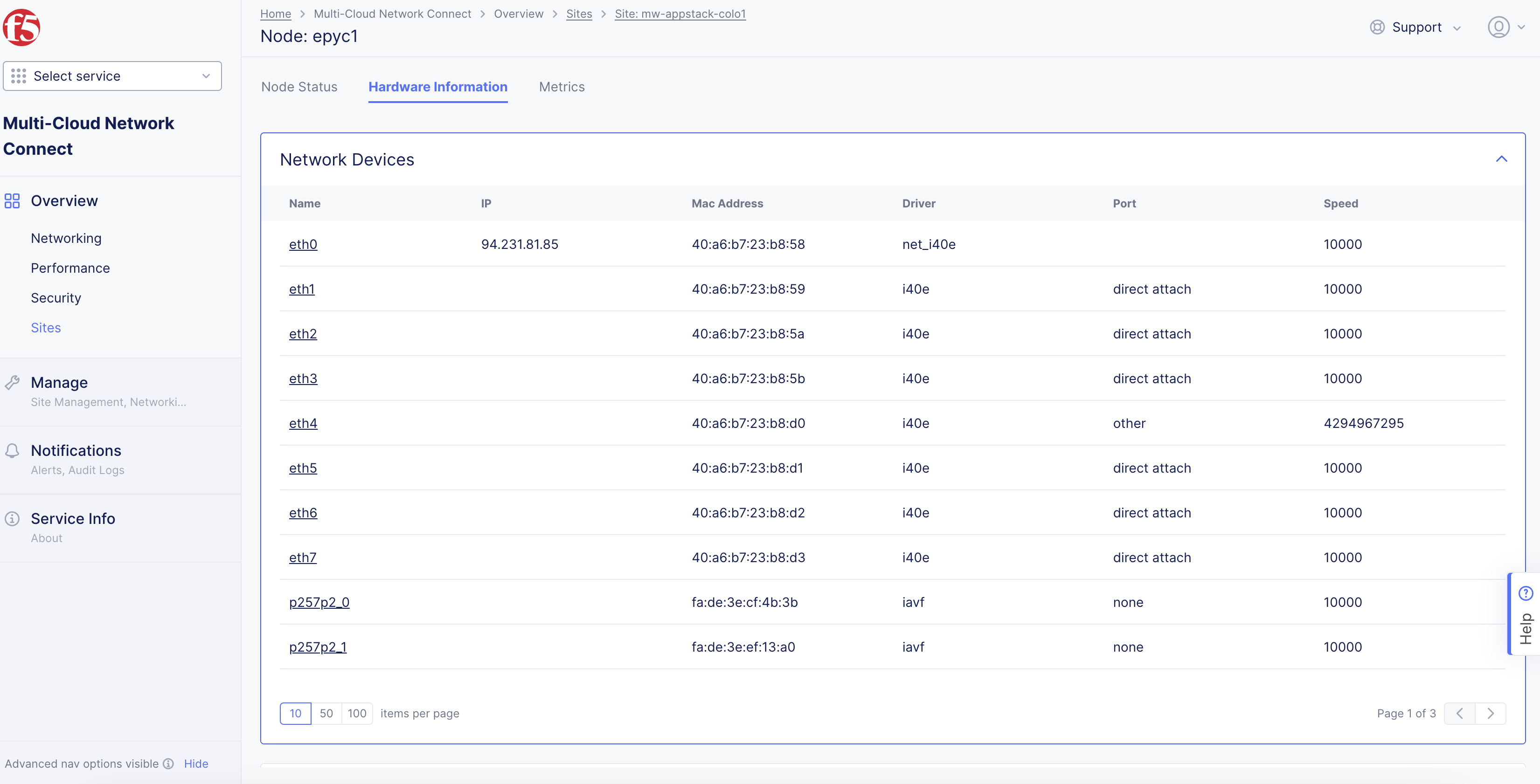
Figure: Node Deployed with SR-IOV Interfaces
Example: CI/CD Using In-Cluster Service Account
This example provides steps to set up CI/CD jobs for your app deployments using an in-cluster service account, to access local K8s API for the managed K8s clusters on App Stack sites.
Perform the following to set up the GitLab runner for your apps on App Stack sites using managed K8s:
Step 1: Start creating K8s cluster object.
-
Select the
Distributed Appsworkspace from the home page or theSelect workspacedrop-down menu. -
Navigate to
Manage>Manage K8s>K8s Clusters. -
Click
Add K8s Cluster. -
Enter a name in the
Metadatasection. -
In the
Accesssection, select theEnable Site Local API Accessoption from theSite Local Accessmenu. -
In the
Local Domainfield, enter a local domain name for the K8s cluster in the<sitename>.<localdomain>format. -
From the
VoltConsole Accessmenu, select theEnable VoltConsole API Accessoption.
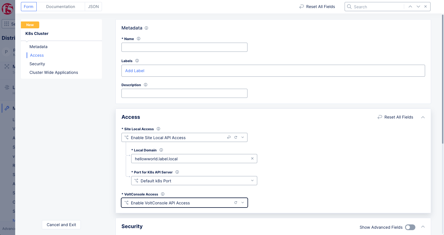
Figure: Enable Local K8s and Console Access
Step 2: Add role and role binding for your service account.
First create a role with policy rules to set full permissions to all resources. Afterward, create role binding for this role to your service account.
Step 2.1: Create K8s cluster role.
-
From the
K8s Cluster Rolesmenu in theSecuritysection, select theCustom K8s Cluster Rolesoption. -
Click in the
Cluster Role Listfield and then clickAdd Itemto create and attach a role. Configure the cluster role object per the following guidelines:-
Enter a name for your cluster role object in the
Metadatasection. -
In the
Cluster Rolesection, selectPolicy Rule Listin theRule Typemenu. -
Click
Add Item. -
Set policy rules in the cluster role sections allowing access to all resources.
-
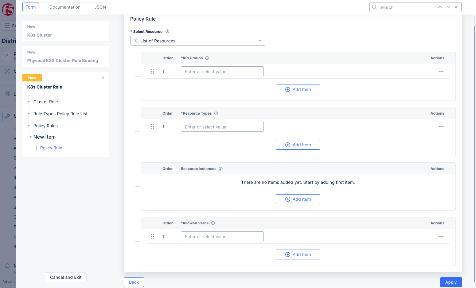
Figure: K8s Cluster Role Rules
-
Click
Applyat the bottom of the form to save the policy rule. -
Click
Continueat the bottom of the form to save the cluster role.
Step 2.2: Create role binding.
-
Create a role binding and then attach your role to the role binding for the service account specified in the
system:serviceaccount:$RUNNER_NAMESPACE:defaultformat. This example uses thetestnamespace. -
Select the
Custom K8s Cluster Role Bindingsoption from theK8s Cluster Role Bindingsmenu. -
Click in the
Cluster Role Bindings Listfield, and then clickAdd Itemto create and attach it:-
Enter a name in the
Metadatasection. -
From the
K8s Cluster Rolemenu, select the role you created in the previous step. -
In the
Subjectssection, clickAdd Item. -
In the
Subjectssection, clickAdd Item. -
From the
Select Subjectmenu, selectService Account.
-
-
Enter a namespace and service account name in the
NamespaceandNamefields, respectively. This example setstestnamespace andsystem:serviceaccount:test:defaultas the service account name.
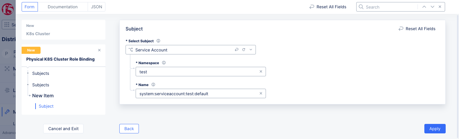
Figure: K8s Cluster Role Binding with Service Account as Subject
-
Click
Apply. -
Click
Continueto create and assign the K8s cluster role binding.
Step 3: Complete cluster creation.
Verify that the K8s cluster role and role binding are applied to the cluster configuration and click Save and Exit.
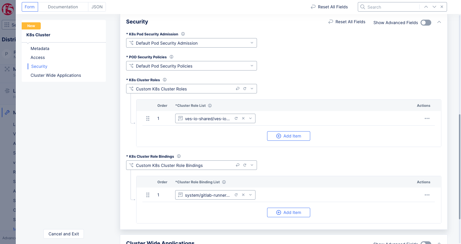
Figure: K8s Cluster with Role and Role Binding
Step 4: Create an App Stack site to attach the cluster created in the previous step.
-
Select the
Multi-Cloud Network Connectworkspace from the home page or theSelect workspacedrop-down menu. -
Click
Manage>Site Management>App Stack Sites. -
Click
Add App Stack Siteto start creating an App Stack Site. -
Configure your App Stack site per the guidelines provided in the Create App Stack Site guide.
-
Select
Enable Site Local K8s API accessfrom theSite Local K8s API accessmenu. -
Click on the
Enable Site Local K8s API accessfield and select the cluster you created in the previous step from the list of clusters displayed.
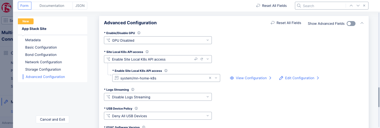
Figure: App Stack Site Enabled with Site Local K8s Access
- Click
Save and Exit.
Step 5: Register your App Stack site and download the kubeconfig file.
Deploy a site matching the name and hardware device you defined in the App Stack site.
-
Click
Manage>Site Management>Registrationsand approve your App Stack site registration. -
Check that your site shows up in the
Sites>Site Listview. -
Click
Managed K8s>Overviewand find your K8s cluster. -
Click
...under theActionscolumn for your cluster to download its kubeconfig. You can download the local or global kubeconfig file. -
Ensure that the domain name you specified in the K8s cluster is resolved.
Note: For example, you can add an entry in the
/etc/hostsfile for your domain with the VIP of the K8s cluster object. You can obtain the FQDN and IP address from the kubeconfig file and Console (node IP address from your App Stack siteNodesview), respectively. However, it is recommended that you manage DNS resolution for your domains.
Step 6: Deploy a GitLab runner onto your K8s cluster.
- Download the GitLab runner reference values file. See GitLab Runner Helm Chart for more information.
curl https://gitlab.com/gitlab-org/charts/gitlab-runner/-/raw/master/values.yaml > values.yaml
- Enter your GitLab URL and runner registration token to the
values.yamlfile.
echo "gitlabUrl: https://gitlab.com/" >> values.yaml
echo "runnerRegistrationToken: foobar" >> values.yaml
Note: Replace
foobarwith your registration token.
- Set the
KUBECONFIGenvironment variable to the downloaded kubeconfig file.
export KUBECONFIG=<PK8S-Kubeconfig>
- Deploy GitLab runners onto your K8s cluster using the kubeconfig file and the
values.yamlfile. The commands depend on the Helm version.
For Helm 2:
helm install --namespace <PK8_NAMESPACE> --name gitlab-runner -f values.yaml gitlab/gitlab-runner
For Helm 3:
helm install --namespace <PK8_NAMESPACE> gitlab-runner -f values.yaml gitlab/gitlab-runner
Note: You can create a namespace in your K8s cluster using
kubectl.
Step 7: Verify that the runners are operational.
Check that the pods are started in Console.
-
Click
Managed K8s>Overview. -
Click the name of your App Stack site.
-
Select the
Podstab to check that the runner pods are started. -
Go to your GitLab CI/CD page and verify that the same runners are created there.
-
Go to your project in GitLab and navigate to
Settings>CI/CD. -
Click
Expandin theRunnerssection. -
Check that your runners appear under
Available Specific Runners.
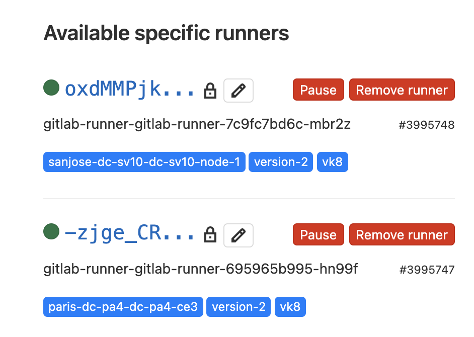
Figure: GitLab Runners
Note: The names of the runners are the same as the runner pod names in Console.
Concepts
API References
On this page:
- Objective
- Virtual K8s and Managed K8s
- Reference Architecture
- Prerequisites
- Restrictions
- Configuration
- Create Managed K8s Cluster
- Attach K8s Cluster to App Stack Site
- Manage PK8s with VMs
- Export VMs on PK8s
- Create Virtual Machines and Pods with SR-IOV
- Example: CI/CD Using In-Cluster Service Account
- Concepts
- API References