Configure Multi-Node Site Network Using Fleet
Objective
This guide provides instructions on how to configure the networking configuration for each node in a multi-node site using F5® Distributed Cloud Services Fleet. All the multi-node sites belonging to the Fleet will be configured equally, and you can further enhance the security by adding a network firewall to the Fleet, to ensure consistent security policy across all the sites in the Fleet. These instructions cover the following:
-
IP address management of outgoing interfaces (toward the Internet).
-
IP address management of interfaces toward inside networks.
-
Segmentation of subnets using virtual local area networks (VLANs).
For information on how to use networking, see Networking.
For information on how to create a Fleet, see Create a Fleet.
For information on how to create and manage sites, see Site Management.
Prerequisites
-
A Distributed Cloud Services Account. If you do not have an account, see Getting Started with Console.
-
A multi-node site.
Configuration Diagram
The following diagram shows an example topology for the use case presented in this guide:
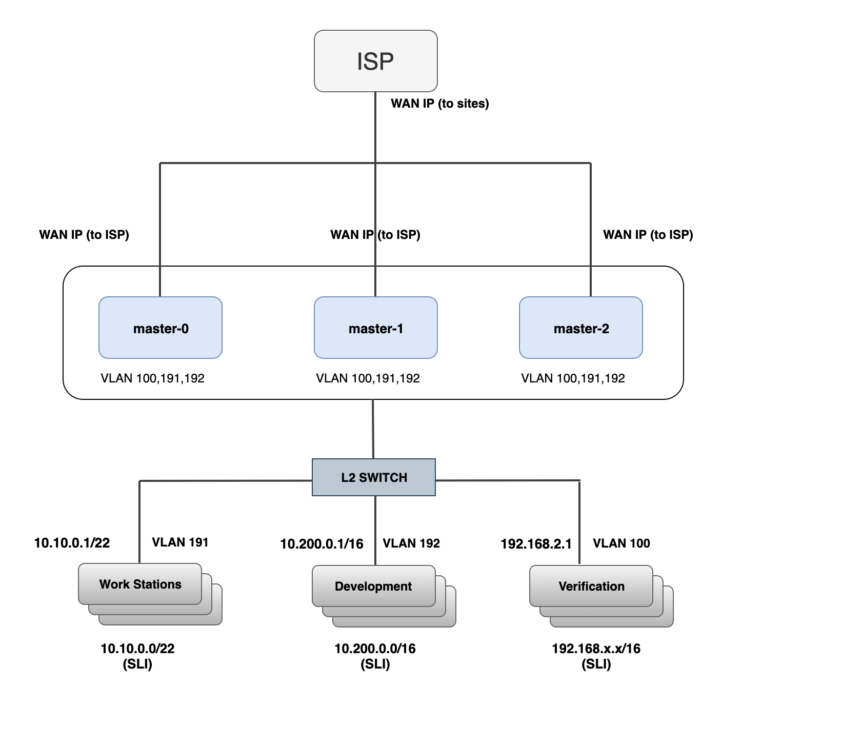
Figure: Sample Network Topology
The example in this topology sets up a multi-node site as a network gateway for inside networks. The gateway has three master nodes and a Layer 2 switch with three VLANs for segmentation of employee workstations, development servers, and test servers. To set up this topology, you need to configure the following in the Fleet object:
-
Two virtual networks: one outside network and one inside network. This example creates inside and outside networks as part of Fleet.
-
Set up the following network interfaces:
- Dedicated Interfaces on the Site Local Outside (WAN).
Note: The IP addressing must be static or a fixed DHCP lease from an upstream DHCP server. Changing of SLO IP addresses in a multi-cluster setup is currently not supported.
-
Ethernet Interface for the Site Local Inside Network. We will configure Static Node Address, a DHCP Server, and DHCP Fixed Leases for internal hosts such as printers.
-
Set up a site local breakout from the Inside to Outside network using the network connector with SNAT.
-
Finally, apply the Fleet with the above objects to your multi-node site to enable the network connectivity.
Create Fleet
Step 1: Start Fleet configuration.
-
Log into F5® Distributed Cloud Console (Console).
-
Click
Multi-Cloud Network Connect.
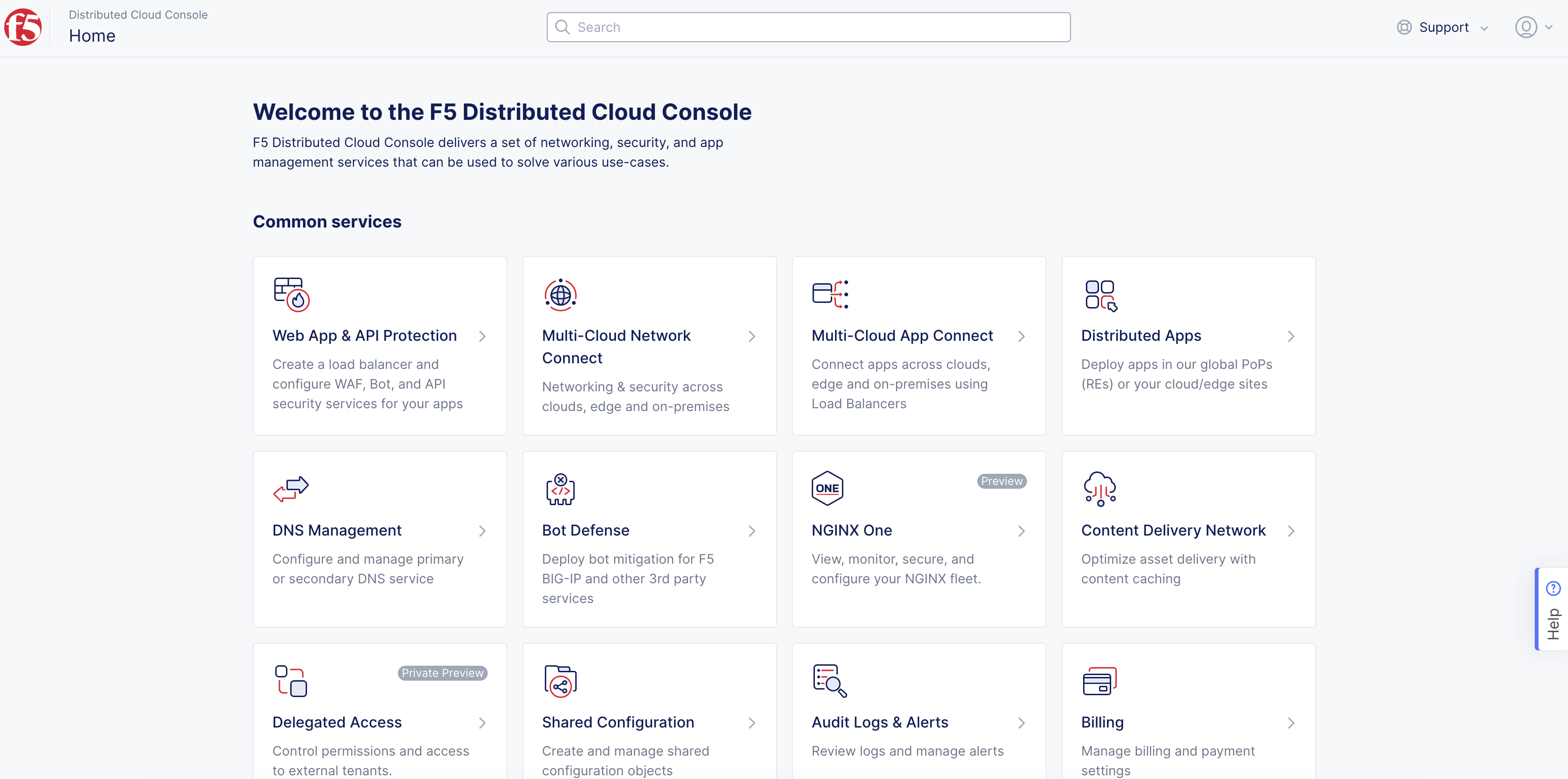
Figure: Console Homepage
- Click
Manage>Site Management>Fleets.
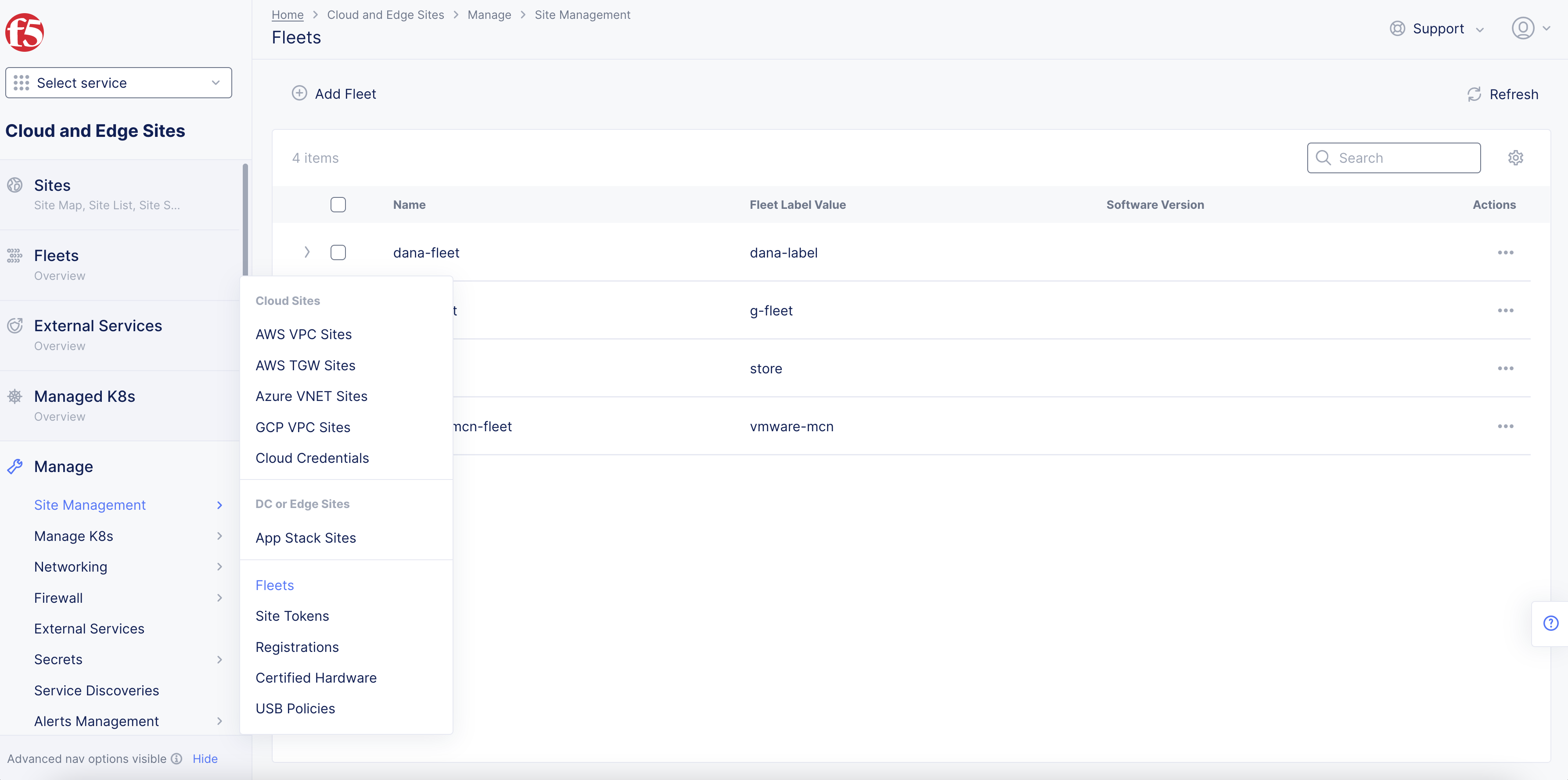
Figure: Navigate to Fleets
- Click
Add Fleet.
Step 2: Add your Fleet name and metadata.
-
In the
Metadatasection, enter a mandatory Fleet name in theNamefield. -
Optionally, select a label and enter a short description.
Step 3: Configure your Fleet label, virtual networks, and software versions.
-
In the
Fleet Configurationsection, enter a mandatory value for the Fleet label in theFleet Label Valuefield. -
Configure the following optional fields:
-
Select an outside virtual network from the
Outside (Site Local) Virtual Networkmenu. To create a new network, clickAdd Item. In the page that appears, configure the fields. After you finish, clickContinue. -
Select an inside virtual network from the
Site Local Inside Virtual Networkmenu. To create a new network, clickAdd Item. In the page that appears, configure the fields. After you finish, clickContinue. -
In the
Software Versionfield, enter a software version. -
In the
Operating System Versionfield, enter an operating system version.
-
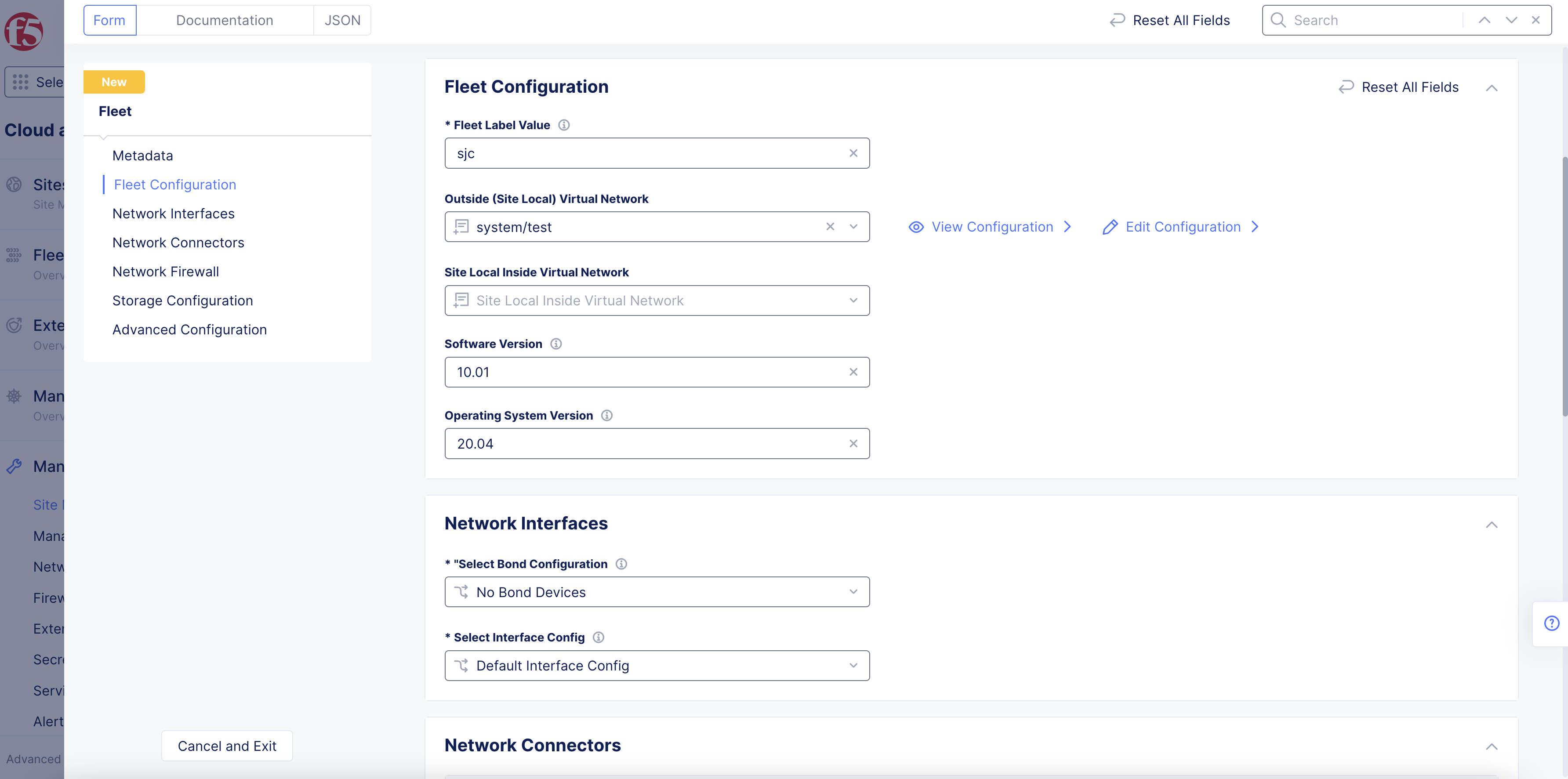
Figure: Fleet Label, Networks, and Versions
Step 4: Select or create network interfaces for the sites in your Fleet.
Step 4.1: Add and configure a new bond device.
-
From the
Select Bond Configurationmenu, select if you want to configure a new bond interface withConfigure Bond Interfaces:-
Click
Add Item. -
From the
Bond Device Namemenu, clickSee Common Values. Select a value from the list displayed.
-
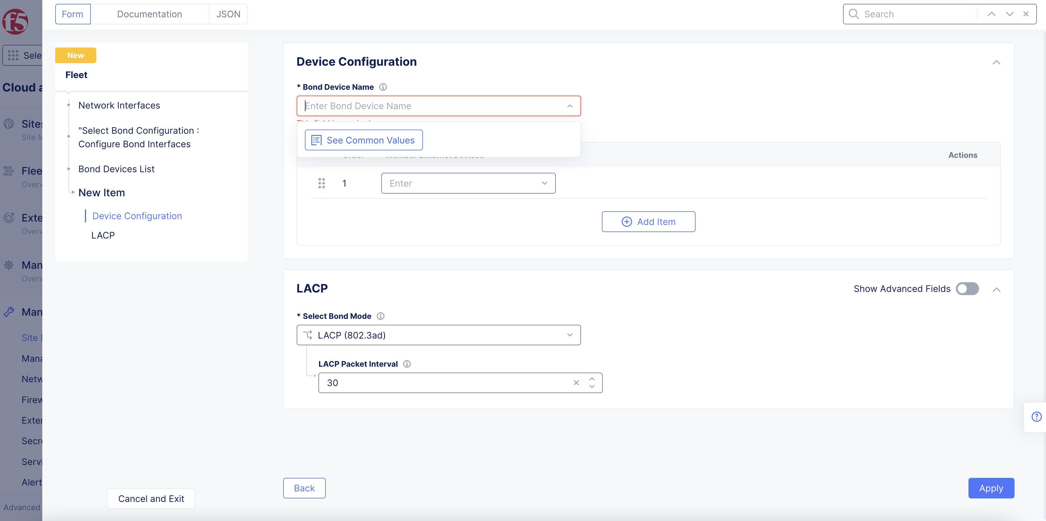
Figure: Fleet Bond Configuration
-
From the
Member Ethernet Devicesmenu, clickSee Common Values. Select a value from the options displayed. You can add more devices using theAdd Itemoption. -
From the
Select Bond Modemenu, select how the bonding occurs. If you selectLACP (802.3ad), optionally enter a packet interval value in theLACP Packet Intervalfield. The default value is30. -
Click
Apply.
Step 4.2: Configure non-bond interfaces.
-
From the
Select Interface Configmenu, selectList of Interfaces. -
From the
List of Interfacesmenu, selectAdd Item. -
In the
Namefield, enter an interface name. -
From the
Interface Config Typemenu, selectDedicated Interface. -
From the
Interface Devicemenu, clickSee Common Values, and then selecteth0. -
From the
Select Configuration for Cluster or Specific Nodemenu, selectCluster, All Node of the site. -
From the
Select Primary Interfacemenu, confirm whether this interface is primary. -
Click
Continue.
Note: WAN IP address configuration is out of scope for this documentation.
Step 4.3: Configure inside network interface for a development network.
You can configure inside network interfaces using the following methods:
-
Interface with DHCP Server: This enables you to specify the DHCP pool settings. You can also statically map IP address based on hostname or MAC addresses.
-
Interface with DHCP Client: This enables the interface to obtain IP addresses from a DHCP server.
-
Interface with Static Mapping: This enables you to manually assign IP addresses to nodes.
Interfaces with DHCP Server Method:
-
From the
Select Interface Configmenu, selectList of Interfaces. -
From the
List of Interfacesmenu, selectAdd Item. -
Enter a name in the
Namefield for the development subnetwork. -
From the
Interface Config Typemenu, selectEthernet interface. -
Click
Configure. -
From the
Ethernet Devicemenu, clickSee Common Values. Select a value from the displayed list. -
From the
Select Untagged or VLAN taggedmenu, selectVLAN Idand then enter aVLAN Id. -
From the
Select Interface Address Methodmenu, selectDHCP serverand then clickConfigure. -
Under the
DHCP Networks, Pools, Gatewaysection, clickConfigure. -
From the
Select Network Prefix Methodmenu, selectNetwork Prefixand then enter a network prefix. -
From the
DHCP Pool Settingsmenu, selectInclude IP Addresses from DHCP Pools. -
Click
Add Itemand then enter theStarting IPandEnding IPper your choice. -
Set the default gateway and DNS server addresses per your choice.
-
Click
Apply. -
In the
Interface Addresssection, enableShow Advanced Fields. -
From the
Select Interface Addressingmenu, selectConfigured. -
Click
Add Item. -
Enter the site node, and then enter an IPv4 address. You can add more static mappings using the
Add Itemoption. This is the interface configuration from the master nodes toward the development subnet. -
In the
Fixed IP Assignments for Clientssection, add the MAC address to IPv4 mappings. You can add more static mappings using theAdd Itemoption. -
Click
Apply. -
Click
Applyto create the interface and add to your Fleet. -
Click
Continue.
Interfaces with Static Mapping Method:
-
From the
Select Interface Configurationmenu, selectList of Interfaces. -
From the
List of Interfacesmenu, selectAdd Item. -
Enter a name in the
Namefield for the development subnetwork. -
From the
Interface Config Typemenu, selectEthernet interface. -
Click
Configure. -
From the
Ethernet Devicemenu, clickSee Common Values, and then select an option. -
From the
Select Configuration for Cluster or Specific Nodemenu, selectCluster, All Nodes of the Site. -
From the
Select Untagged or VLAN taggedmenu, selectVLAN Idand then enter aVLAN Id. -
Enable the
Show Advanced Fieldsoption. -
From the
Select Interface Address Methodmenu, selectStatic IP. -
From the
Select Static IP Configurationmenu, selectSpecific Node. -
Enter the
IP address/Prefix Lengthand optionally addDefault Gateway. -
In the
Virtual Networksection, selectSite Local Network Insidefrom theSelect Virtual Networkmenu. -
From the
Select Primary Interface, select whether this interface is a primary interface. -
Click
Apply. -
Click
Continue.
Step 4.4: Configure inside network interface toward workstations and test server subnetworks.
Follow the same steps as that of Step 4.3 above, with the IP addresses of the node interfaces toward the other two subnetworks and DHCP pool settings for the clients.
The following instructions show interface configuration in the DHCP server mode. Static mapping is not shown. If you are using static mapping, follow the instructions in the Interfaces with Static Mapping Method subsection in Step 4.3. Create interfaces for each VLAN with node to IP address mapping. For this section example, there are three VLANs and three nodes, so three interface objects are required with each interface consisting of three IP mappings.
DHCP network settings for VLAN 191 (interface name subnet-clients-vlan191):
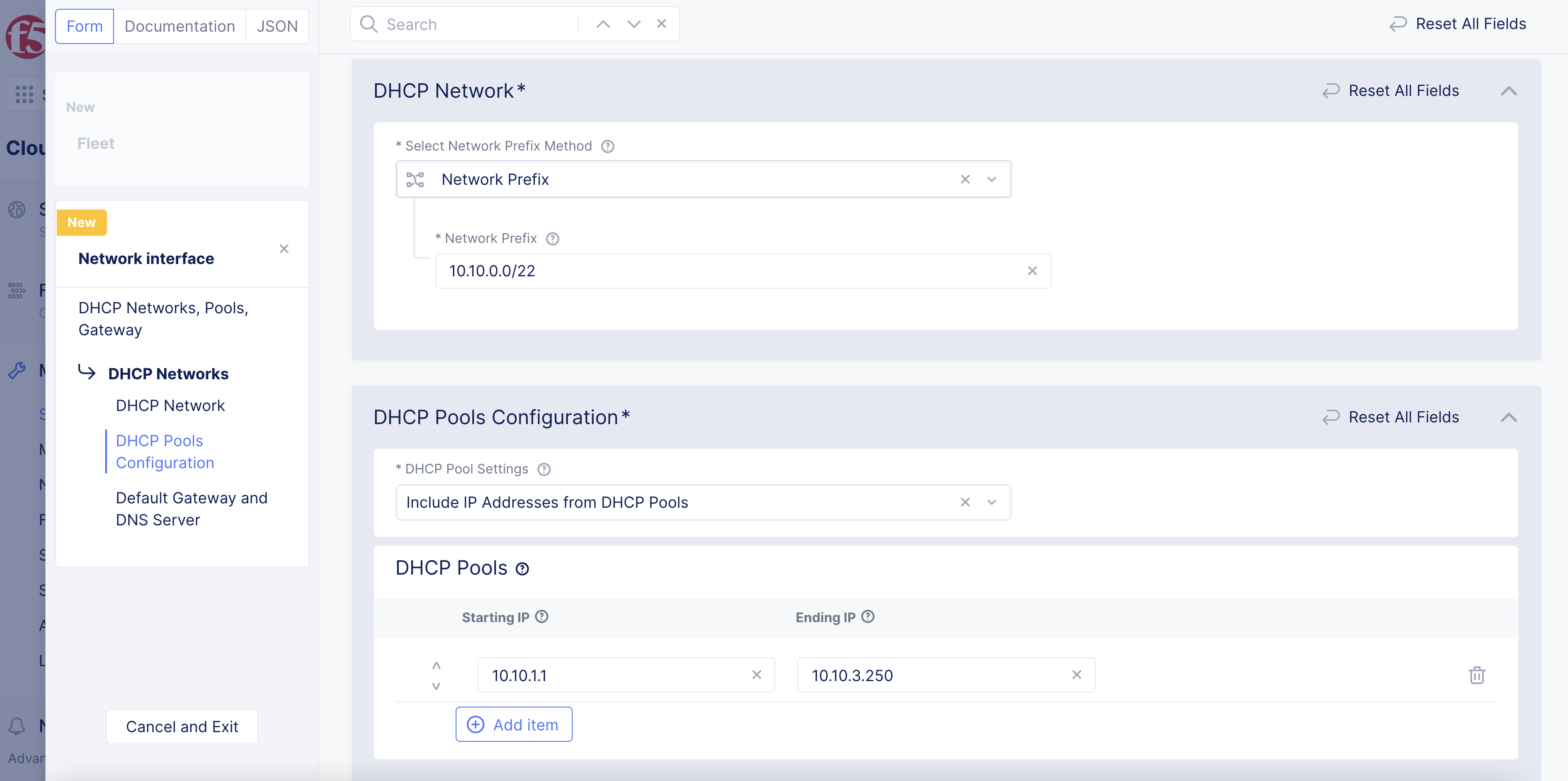
Figure: DHCP Configuration for VLAN 191
Static mappings for VLAN 191:
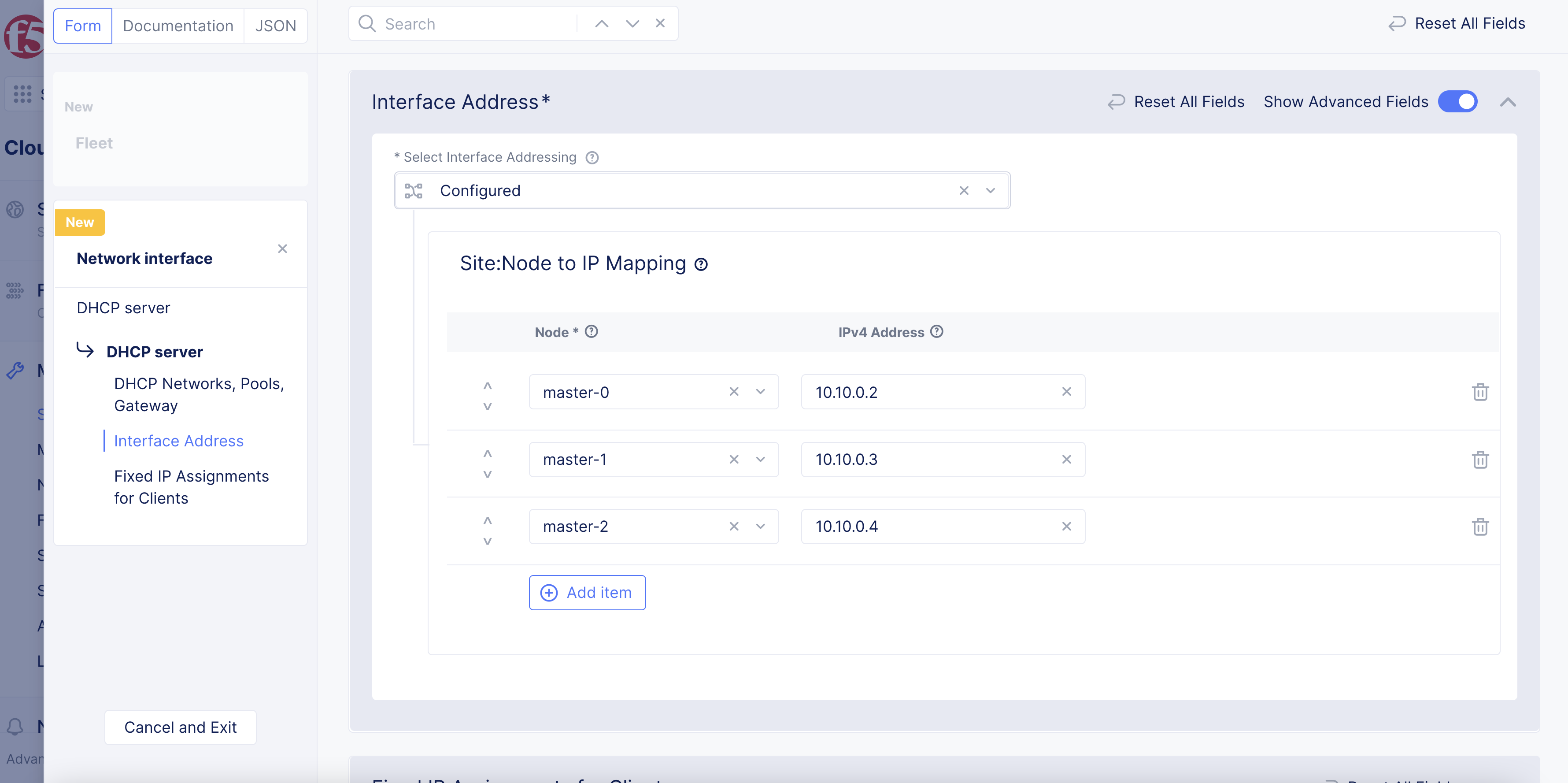
Figure: Static IP Configuration for VLAN 191
DHCP network settings for VLAN 192 (interface name subnet-vmware-vlan192):
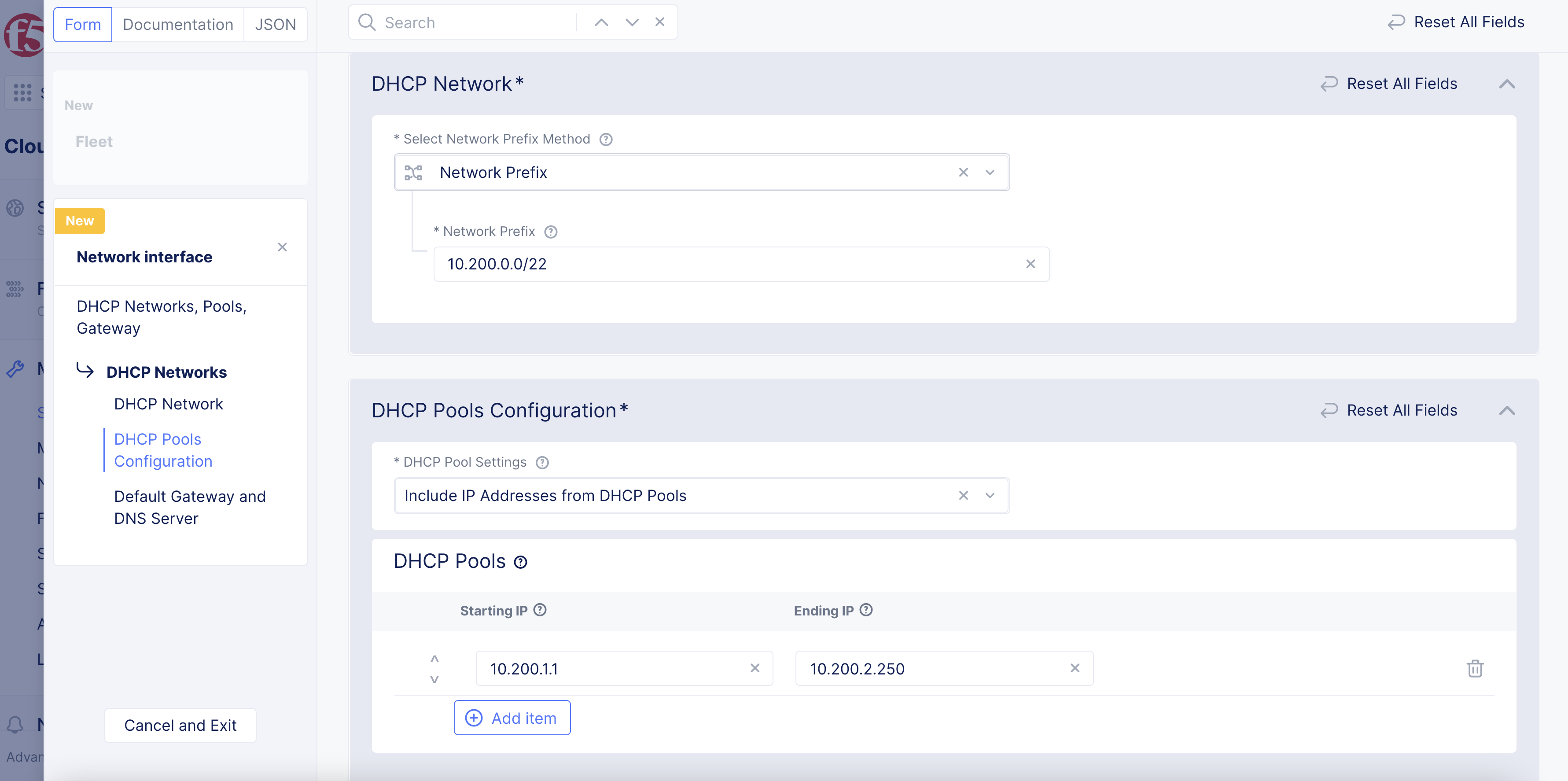
Figure: DHCP Configuration for VLAN 192
Static mappings for VLAN 192:
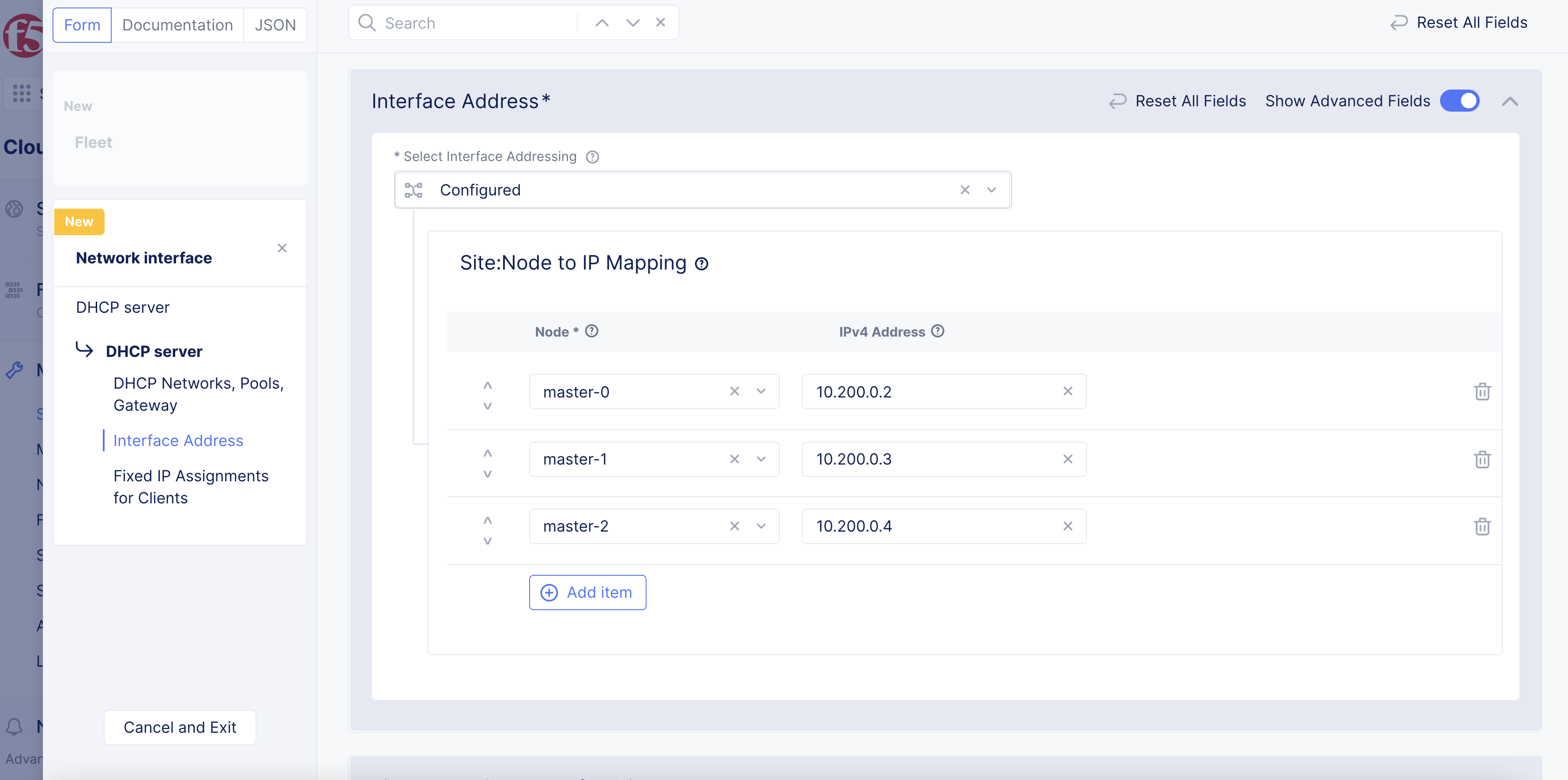
Figure: Static IP Configuration for VLAN 192
Step 5: Configure network connectors.
-
To select an existing network connector:
-
Click
Select Network Connector. -
From the list that appears, find and select the network connector, and then click
Select Network Connector.
-
-
To create a new connector, click
Add new Network Connector. -
Complete the configuration using the instructions provided at Network Connectors.
Step 6: Complete Fleet network creation.
Click Save and Exit.
Apply Fleet Label to Site
After your Fleet is created and configured, you will need to apply its label to your multi-node site.
Step 1: Navigate to your Site.
-
In
Multi-Cloud Network Connect, clickSites, and then clickSite List. -
Find your site, click
...and then clickManage Configuration. -
Click
Edit Configurationto edit your site properties.
Step 2: Apply the Fleet label.
-
In the
Labelsbox form, start by typing “fleet” and you will see the key-value pairves.io/fleet. Select this key-value pair. -
Type the name of your Fleet label, and then select it.
Step 3: Save the configuration.
Click Save changes.